Week 7 State of charge estimation
A battery management system is a electronic system which looks after the whole battery in terms of temperature, voltage, circuit etc to avoid the system from getting damaged or under-performance. It keeps the battery inside the safe operating zone. It monitors it's state,calculates secondary data,reports,controls the environment,authenticates and balances the system.
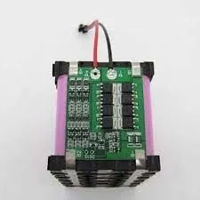
A battery pack consists of many cells with each cell of different capacity. The capacity increases or decreases with the increase in the no. of charging and discharging cycle. The battery pack must stop discharge as soon as any one cell amongst all gets out of charge even while other hold some charge. Same way, the charging must stop as soon as any cell reaches it's full capacity. Failing to which would lead to thermal runaway and damage the battery pack.
Balancing- Cell balancing is equalizing the voltage amongst each cells. By doing so, all the cells that constitute the battery pack will have same Soc. This is actually important due to manufacturing inconsistencies due to which no two cell are indentical in terms of performance. Even the brand new cell have slight difference in capacity, impedence, self-discharge rate. This causes the cells to age at different rate resulting in significant energy imbalance in the module. This leads to degredation in performance of the battery pack.
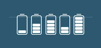
There are 2 types of balancing which are 1)passive,2)active cell balancing
Passive or resistor bleeding balancing is the process of cell balancing in which the cell which needs to be balanced losses the charge. The cell which have the highest charge go through charge removal as the charge is send to the resistor and there is resistance faced by the charge and this is removed in form of heat. In this process, the cell with the least charge acts as the standard cell and all the other cells with greater charge go through the charge removal phenomena to reach the level of the less charge cell. This helps all the cells to discharge to 0 Soc and get charged to 100%. In this way, all the cells are balanced. The process is done only at charging. There is loss of charge in form of heat. Due to heat involved in this process, an additional cooling system is required to cool the battery pack.
Active cell balancing is the process of cell balancing which is a better energy efficient process in which the cell with greater charge donates the same to the cell with less charge. In this manner, the cell can be charged to 100% Soc with all the cells at the same level.
1)Simulation
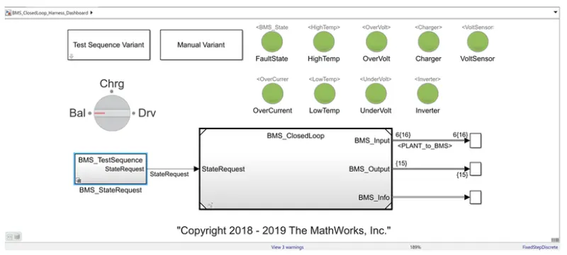
The model
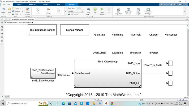
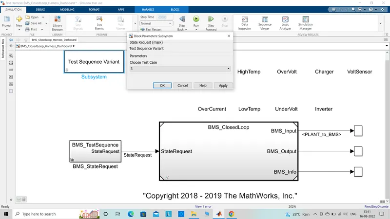
Beginning with test sequrence variant, it has 3 test cases that has to been run for observation.
Manual variant block. BMS state request block is used to give state request command. This is connected to a BMS closed loop subsystem block which has the BMS plant model inside it. The input is given as state request with 3 outputs of BMS input, BMS output and BMS info and all give the output which has to be controlled. The lamps which are connected to the model are indicating leds and light up as soon as the set condition is reached. Green light will tell us about a good battery health and a red light would indicate a fault in the same. The condition that the system tests are faut state, high temp,over volt,charger,volt sensor,over current,low temp,under volt, inverter.
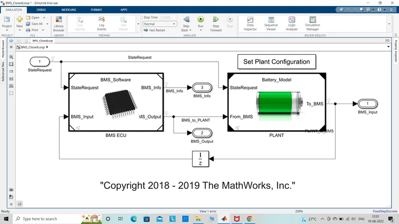
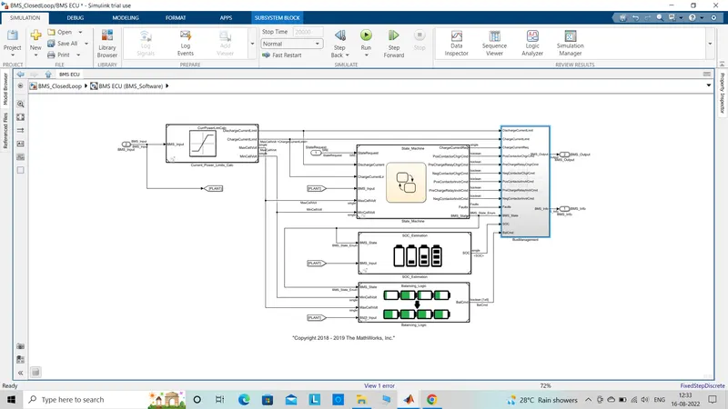
This model begins with the state request from the previous model. This is send to BMS ECU block. The feedback signal from the plant block is BMS_input and the other signal is state request from state machine. The outputs observed are BMS_info and BMS_output. The output is based on the state machine,SOC_estimation, balancing_logic block. The output of which consists of numerous variables and this gives out BMS information.
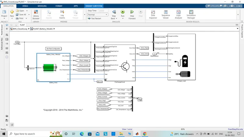
The battery plant contains battery pack, pre charger circuit,charger load block. There are two configurations with 1 module containing 6 cells and another with 16 module containing 96 cells. One module is selected to cut down the simulation time and for simplified calculation. The pre charge circuits are connected. The charge load states that the module is going to connect with a charger and a electric motor. the scope would give out module Soc,cell voltage,pack current,cell temperature,BMS state and cell balancing as output.
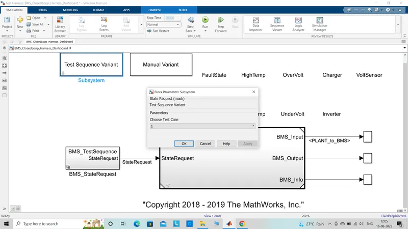
Inside BMS_staterequest,BMS_testsequence, the test case has autmatically got selected as is visible in the next image.
Case1)
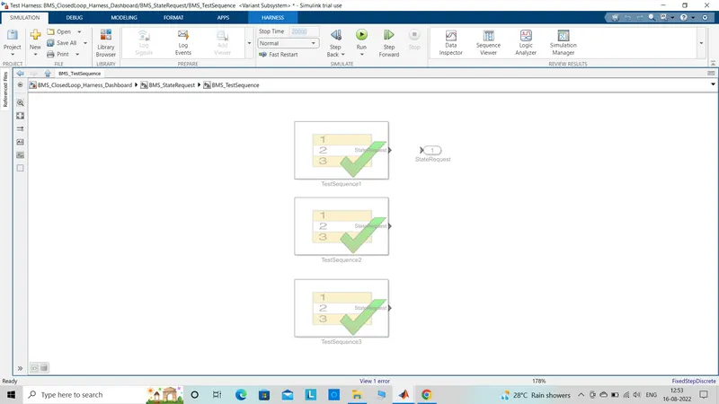
To see what is inside, I have opened the test condition and here the test sequence is visible to me.
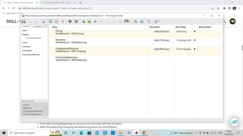
The test sequence progresses in an order and only when the current sequence is completed, the next sequence would come into action. These are:-
*) Driving state req is done for initial 3000secs.
*) Balancing of the cells occur for the next 1000secs.
*) Charging and balancing happens for the next 5000secs.
*) Post charge balancing occurs after 9000secs upto 20000secs which is the simulation end time.
Result
After the simulation model runs for 20000secs, all the lamps light up with green light which indicates that there is no fault in BMS model.
The graph obtained are:-
cell voltage v.s. time
cell temperature v.s. time
Soc v.s. time
pack current v.s. time
BMS state v.s. time
Balancing cmd v.s. time
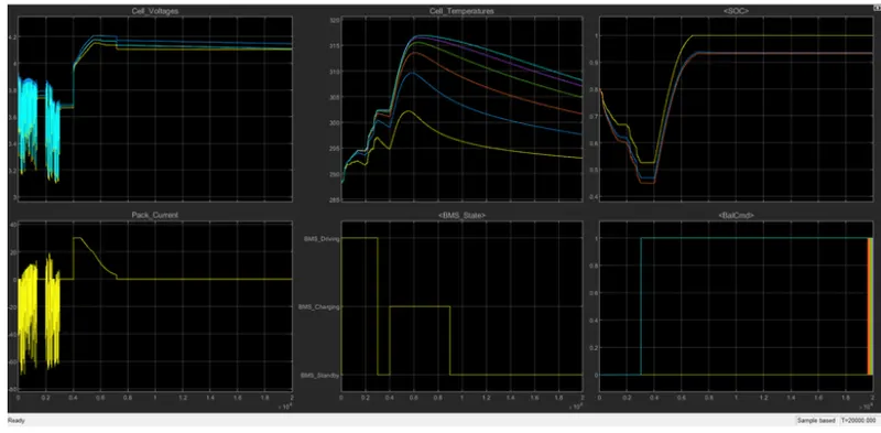
a) Discharging mode(0-3000secs)- All the cells are getting used to light up a load which discharges them which varies within 3.1-3.9V(min-max). During this mode, the temp observed is increased from 288K to 302K. As the charge is getting used up, the Soc reduces 80% to 45%.
b) Balancing mode(3000-4000secs)- For the next 1000 secs i.e. till 4000secs, the cell are getting checked and balanced making the module to enter the stand by condition which makes the voltage of all the cell as constant to nominal 3.7V. The temperature gets reduced at a slow rate because of no flow of current. As there is no loss of charge and voltage also remains constant so the Soc also remains at the same level i.e. 45%.
c) Charging and balancing(4000-9000secs)- For the next 5000secs, the cells are charged and balanced. This in turn increases the voltage to 4.2V which is also known as constant current charging mode. The current observed here is 30A after which constant voltage current charging is adapted and the rate of charging decreases. This reduces the current from 30A-2.6A. The rise in temperature is exponential upto constant current charging and reduces with current flow durinf constant voltage charging mode. During charging mode, Soc increases from 45% to 94%.
d) Post charging balancing(9000-20000secs)- The post charging balancing occurs at standby mode. Cell temperature reduces which reaches the ambient temperature. Soc maintains the same 94% level.
Case 2)
I have followed the same procedure to select case 2 as mentioned earlier.
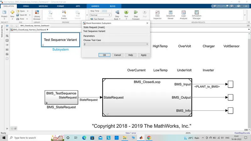
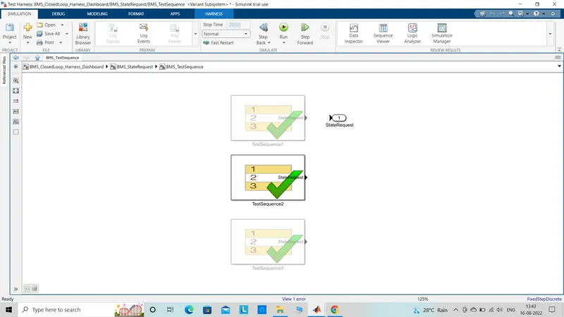
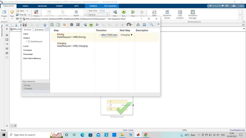
By the test sequence block, it is observed that there are only two cycles. One is driving cycle which is done for 10000secs and another is charging done for next 10000secs.
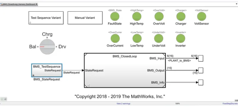
As all the lamps light up with green color that means the model is not having any fault.
Graphs
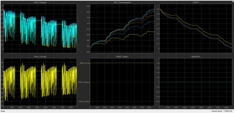
a) Driving mode(0-10000secs)- This case has the pack which is driving a load and in act, the cell voltage decreases from 3.9V to 3.05V. This actually is the cut off voltage and the entire cell gets drained before 9000secs. In doing so, the cell temperature increases from 288K to 322.5K. The charge getting used up to drive the load makes the Soc reduce from 80% to full 0%. The pack is fully discharged as seen in the graph.
There was no cell balancing performed in this case so moving to charging mode.
b) Charging mode(10000-20000secs)- It is clearly observed that the cell was drained to 0% before reaching this mode.
Case 3)
I have followed the same procedure to select case 3 as mentioned earlier.
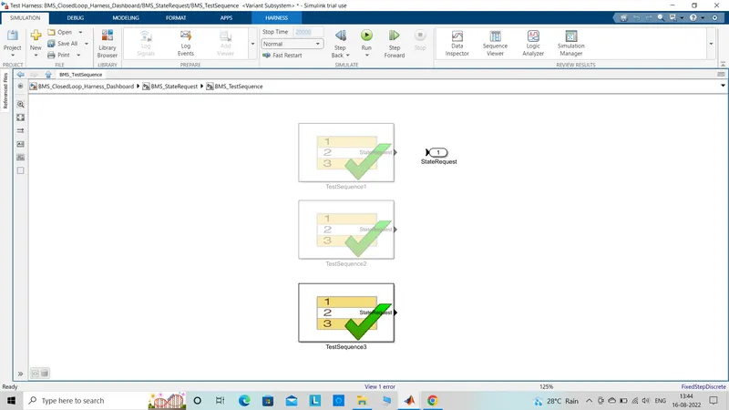
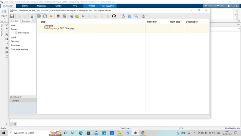
The editor screen displays the only test sequence that is done is charging. Charging is done right from the start to till the end 20000secs.
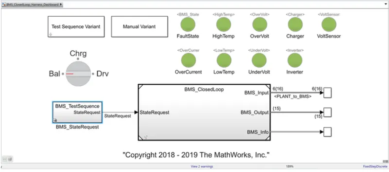
As all the lamps light up with green color that means the model is not having any fault.
Graphs
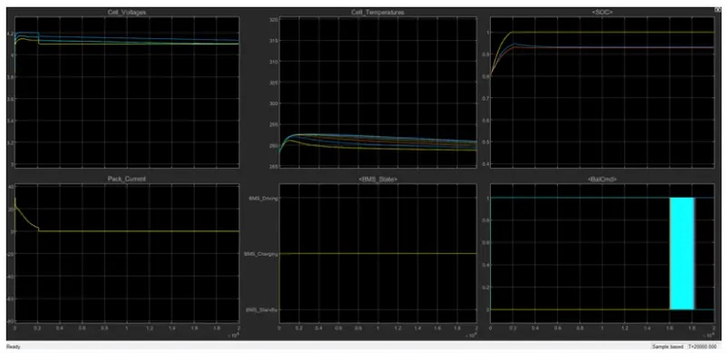
a)Charging(0-20000secs)- It is observed from the graph that the cell voltage increases initially and later after 2000secs the voltage values becomes constant. The pack current begins with 0A and reaches 30A. Later, it starts to fall when constant voltage charging is adapted to 2.5A. It gets fully charged upto 2000secs. Initially, Soc began with 80% and in 2000sec it got up to 100% which is fully charged condition. In doing so, the cell temperature increases initially but when the pack was fully charged then the cell temperature came down to ambient temperature.
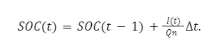
2) Coulomb counting- It is the method to measure the discharging current of a battery and then later integrating the discharging current over time in order to find out the Soc. Coulomb counting method is done to estimate the SOC values, which is estimated from the discharging current and previously estimated SOC values, SOC is calculated by the following equation:
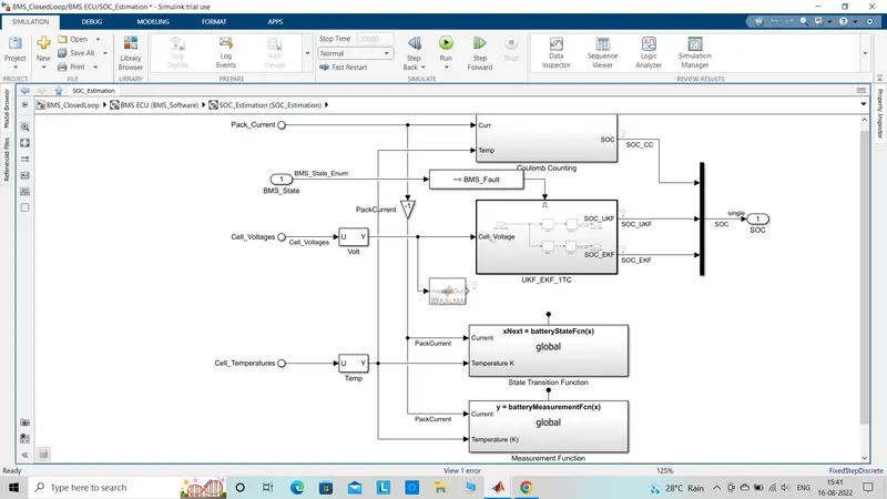
Soc estimation referring the battery model
For this, BMS_closedloop block was opened,BMS_ECU thenSOC_estimation block was opened.
There are total three methods of Soc estimation:-
*)Coulomb counting
*)Unscented Kalman filter
*)Extended laman filter
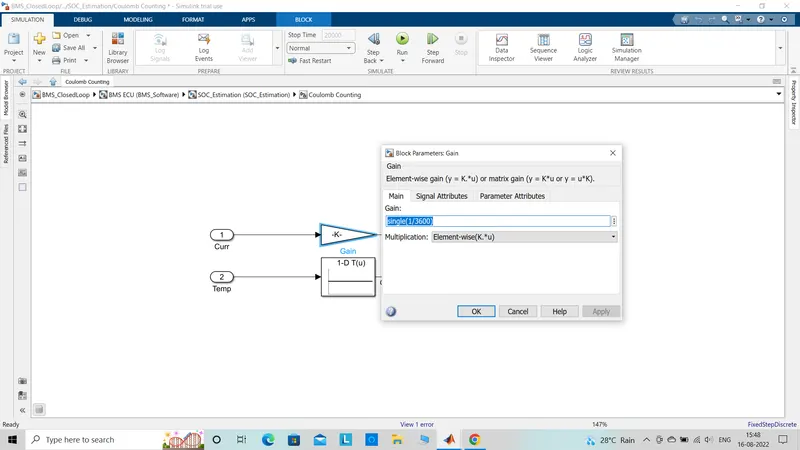
After which, open the coulomb counting block which consists of gain,look-up table,product and discrete time integrator block.
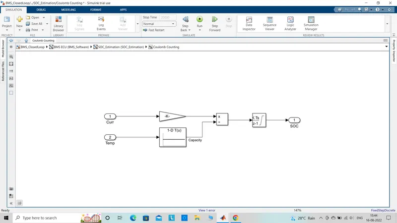
By opening the property window of gain block, the discharge current from the battery value is given as 1/3600 to convert A to Ah.
Coming to the discrete time integrator block.
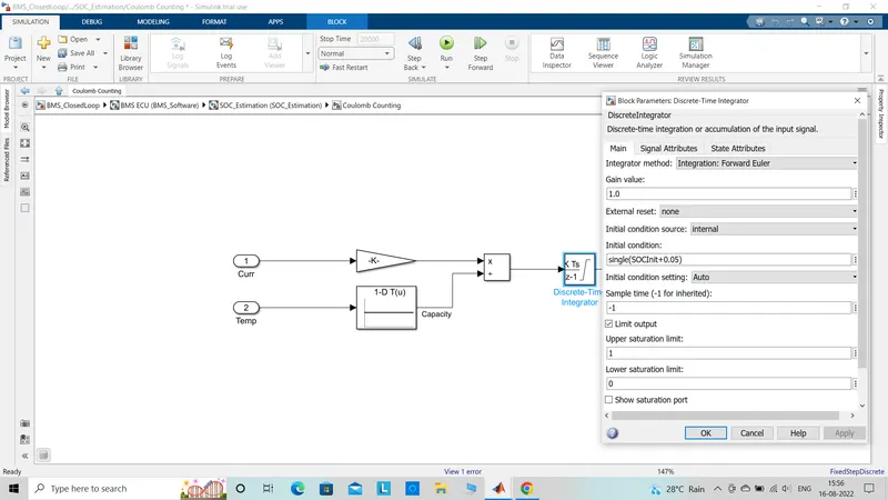
The current is divided by the capacity due to the change in time and then integrated by the gain value of -1 with -1 sample time. the saturation limit are given as 1 to 0. This is done in order to get the Soc value from (0 to 1)* 100 in percentage form. This is Coulomb method and is less complicated with computations when compared to the other two methods.