Week 7 State of charge estimation
Aim: To simulate the test cases using the harness dashboard and write a detailed report, explain coulomb counting method.
Objective:
- Study the model.
- Simulate the 3 test cases from the harness dashboard.
- Study the output results.
- Write a detailed report.
- Explain coulomb counting method.
- Explain how coulomb counting method used in the above model.
Body of the content:
Steps to open the file:
- Using open from the MATLAB window open the folders were the files are extracted.
- Open plant folder.
- Open Battery Model.slx file.
- Click on open project and model.
- Now after simulink window is open, from the current folder open Battery_System.prj file.
- Now open the BMS System from the top bar.
- Now open the harness dashboard as: Test->System->BMS_ClosedLoop_Harness_Dashboard
Simulation of BMS cases:
- The model represents the basic Battery managment system used for Lithium ion batteries.
- The simulation is run for three different cases of the vehicle states(driving, charging and standby) with respect to time.
- There are two battery pack, one consists of the 6 cells and another battery pack contains 96 cells.
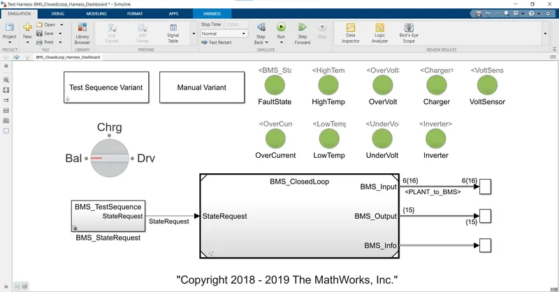
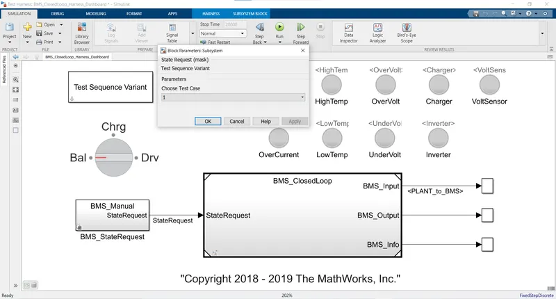
- The below figure shows the harness dashboard:
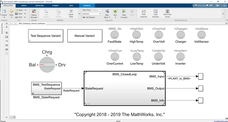
- It mainly consists of:
- Test sequence variant: Used to select the case.
- BMS Closed loop:
- Fault state indicators: Will indicate any faults/warning.
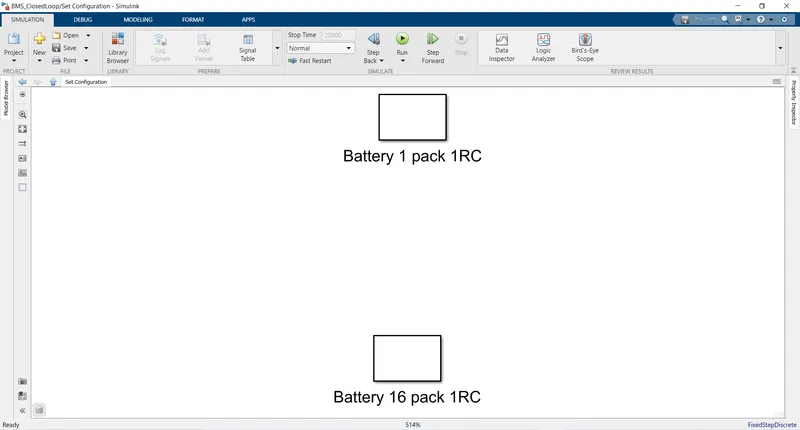
- The below figure shows the BMS system and Battery pack configuration selection:
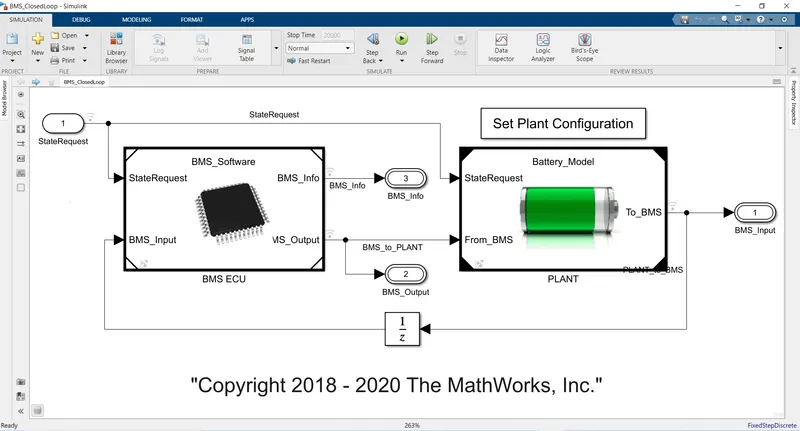
- The BMS closed loop consists of:
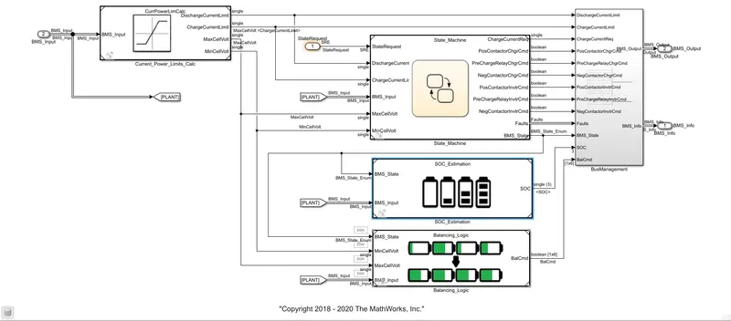
- BMS ECU.
- PLANT.
- The BMS ECU consists of the following:
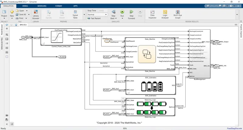
- Current power limit calculation.
- State machine: Defines the state of operation of the BMS.
- There are four states:
- State one defines the state of BMS i.e. standby, driving, charging and fault.
- The second switches the fault state if there are any unsafe parameters(voltage, temperature etc)
- The third state defines the contractors ON and OFF for the precharge and high voltage circuits.(avoid any large inrush current at start)
- The fourth defines the contractors switching of invertor.
- There are four states:
- SOC estimation.
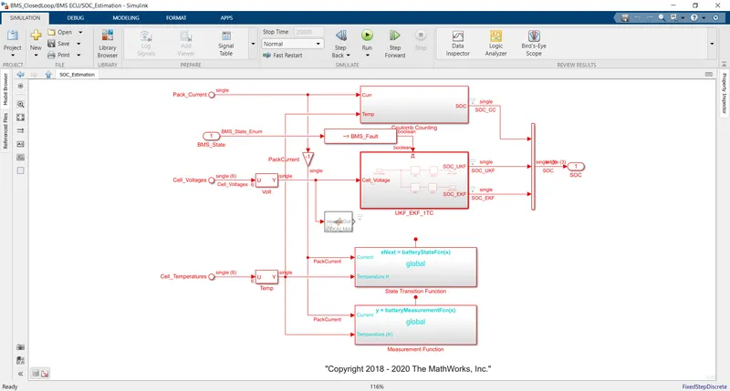
- Three State of Charge estimation methods are used:
- Coulomb Count Method.
- Unscented Kalman filter (UKF).
- Extended Kalman filter (EKF).
- Balancing Logic.
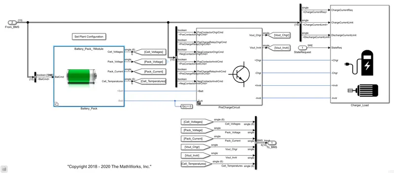
- The PLANT consists of the following arrangment as follows:
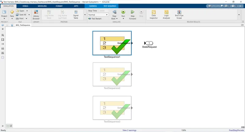
- Case 1
- Here the first test sequence case is selected:
- First case is selected:
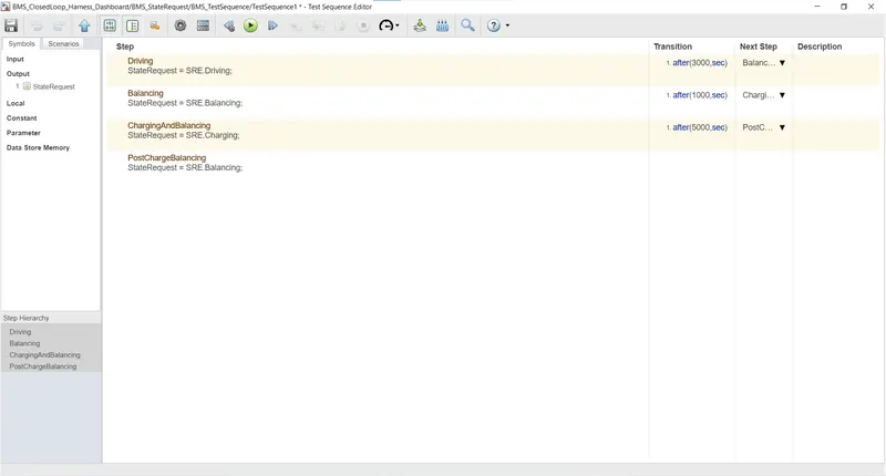
- For the Test case 1 these are the following states:
- Driving - Till 3000 seconds.
- Balancing - next 1000 seconds.
- Charging and Balancing - next 5000 seconds.
- Post charge balancing _ throughout
- Results of Case 1:
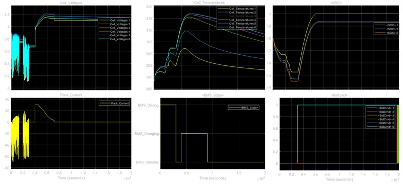
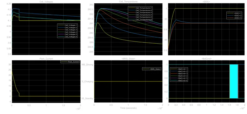
- Cell 6 shows the highest temperature and cell 1 shows the lowest temperature.
- During driving and charging the temperature rises exponentially.
- During driving (0-3000sec) the voltages and current fluctuates as per the conditions.
- During standby(3000-4000sec) the voltage and current remains constant.
- During charging (4000-9000 seconds) the voltage and current attains peaks (cell 2 voltage -4.2 volts).
- SOC (CCM) rises to 100%.
- After 9000 seconds the state is standby, the current flows is zero and SOC remians same.
- Here the first test sequence case is selected:
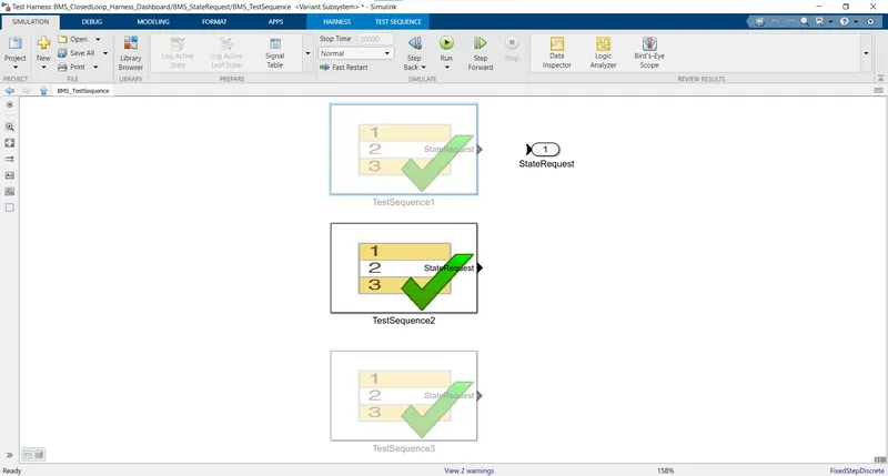
- Case - 2
- Second sequence is selected.
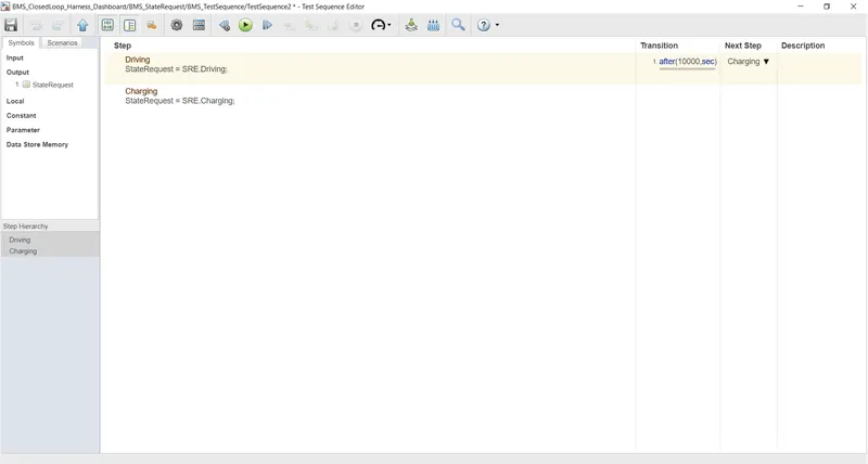
- For this following case these are the states;
- Driving - Till 10000 seconds.
- Charging - after 10000 seconds throughout.
- Here the battery SOC drops to 0 before 9000 seconds, so no further charging occurs as it encounters error.
- Results of Case 2:
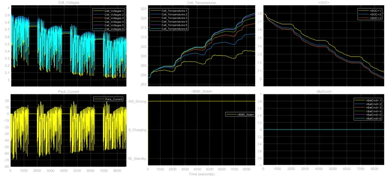
- Here Driving state occurs till 10000 seconds.
- After than charging occurs.
- Cell 6 shows the highest temperature and cell 1 shows the lowest temperature.
- The voltage decreases with respect to time.
- Voltage varies from 3.9volts to 3volts.
- Max current discharge is 70A.
- The SOC is initially 80% and goes to 0% a 8692 seconds.
- So no charging occurs as the SOC becomes 0% the error is encountered.
- Second sequence is selected.
- Case - 3
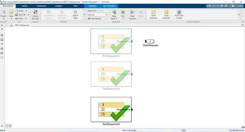
- Selecting third sequence.
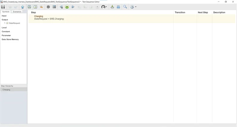
- For this following case these are the states;
- Results of case 3
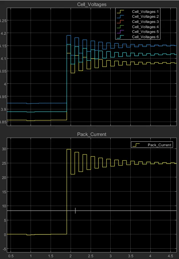
- In this case only charging is done.
- Initially the battery pack is at 80 % of SOC and then its charged to 100%, 94% and 93%(CCM, UKF, EKF respectively) SOC in 2500 seconds.
- All six cells temperatures rise(according to the rate of charge) to peaks till the battery pack is fully charged.
- Peak charge current is around 30A.
- Cell 6 shows the highest temperature and cell 1 shows the lowest temperature.
- Selecting third sequence.
SOC Estimation:
There are various methods used for the estimation of SOC of the battery:
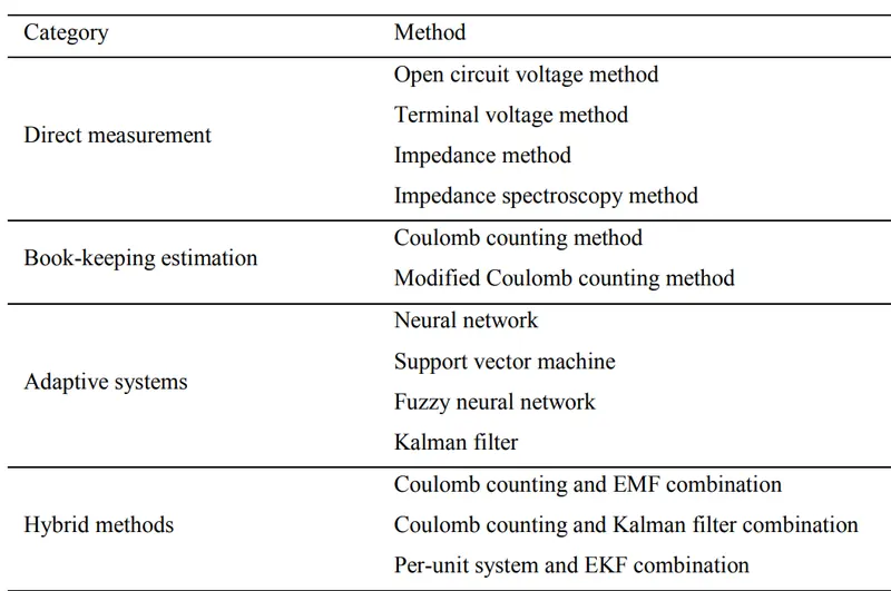
In the present model three methods are used for the SOC calculation:
- Coulomb Count Method.
- Unscented Kalman filter (UKF).
- Extended Kalman filter (EKF).
2. Coulomb Counting:
- It is a method of estimation of SOC, in which the discharging current of the battery is measured and the value of current is integrated over the time to estimate the remaning SOC.
- Here the Current discharge rate (I(t)) and the previous SOC(t-1) value is taken to calculate the estimates present SOC(t).
- The accuracy of the coulomb counting method is greatly affected by temperature, battery history,cycle life and discharge current.
- SOC is calculated by the equation:
- `SOC(t) = SOC(t-1) + I(t)*n*deltat`
SOC estimation in the given model:
- The below figure shows the arrangment of the BMS ECU:
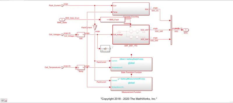
- The SOC estimation module is as follows:
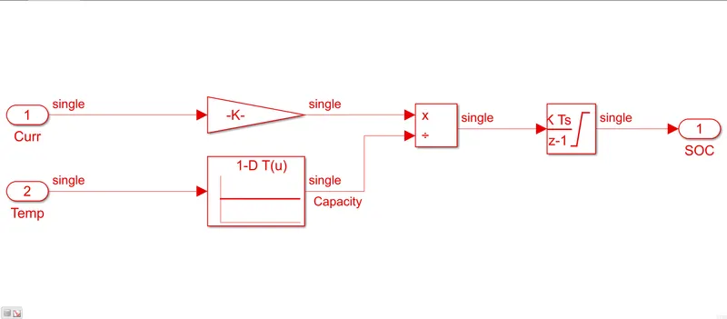
- In coulomb count method:
- Working:
- Here the current and temperature are given as inputs.
- Then by using current value the discharge current per hour is calculated by using the gain block(1/3600).
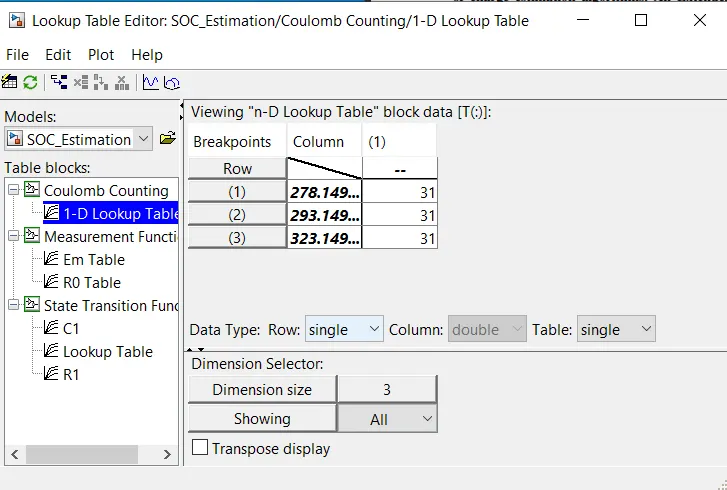
- Then a lookup table is used to find the capacity at specific temperature.
- Then two of these values are divided and the values are integrated(by discreate time integrator) to estimate the SOC.
- The upper and lower limit are 0 to 1.
- Note: The Coulomb counting methods icnorporates errors in the current value calculation which leads to the error in the calculations, it may not be tursted if used as standalone method.
Conclusions:
- The three test cases are simulated and studied and the detailed report is given.
- Methods of SOC estimation are studied and Coulomb count method is explianed.
- The SOC estimation processs in the BMS using Coulomb counting is explained.
References:
- Wen-Yeau Chang, "The State of Charge Estimating Methods for Battery: A Review", International Scholarly Research Notices, vol. 2013, Article ID 953792, 7 pages, 2013. https://doi.org/10.1155/2013/953792
- Matúš Danko, Juraj Adamec, Michal Taraba, Peter Drgona,
Overview of batteries State of Charge estimation methods,
Transportation Research Procedia,
Volume 40,
2019,
Pages 186-192,
ISSN 2352-1465,
https://doi.org/10.1016/j.trpro.2019.07.029