Week -2
Aim: To create the simulink for doorbell operated for 2 seconds and a thermister controlled fan to cool the heater.
Objective of the project:
- Create the simulink model for the simulation of the doorbell.
- Calculate the threshold voltage.
- Create the simulink model for the simulation of the thermister controlled fan.
Body of the content:
Part-1 Doorbell simulation
Working:
The soleonoid is a device which has a coil and a plunger which can be magnetised and the movement/motion can ne achived.
The battery is used to supply the current and the switch is used to operate the circuit, here when the circuit is closed or the switch is closed the current flows through the coil and the plunger is magnetized and the plunger is pulled towards the coil this method is used in the doorbell, so that the plunger strikes the bell repeatedly by the controlled supply.
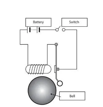
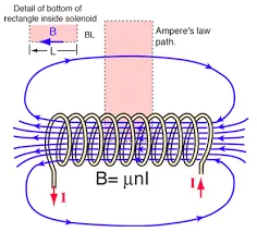
- The simulation of the doorbell in simulink is done by using the following blocks:
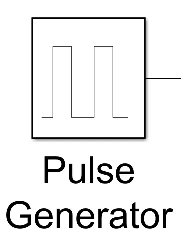
- Pulse generator: Generates the pulse for specified interval and instance.
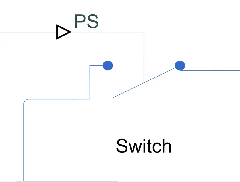
- Switch: It is used to switch on and off the circuit whose input is from pulse generator.
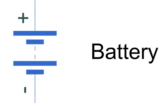
- Battery: Battery supplies the current for the circuit (solenoid).
- Electrical reference: Electrical reference acts as ...
- Solenoid:
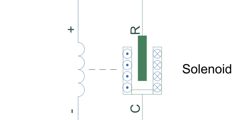
- It is a device which wworks on the principle of the Electromagnetism.
- When the curent is supplied the solenoid shows deflection/motion.
- It has two parts coil and rod(core).
- When the current is supplied to the coil it induces magnetic effect pulling or pushing the rod according to the polarity.
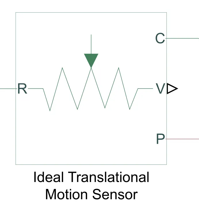
- Ideal Translational motion sensor: It is used to measure the linear displacement of the rod.
- Solver configurations: It is used to define the settings used to solve the simulations.
- Mechanical Translation refererance: Use to add as a referance to mechanical system or connects the ports that are rigidly fixed to frame.
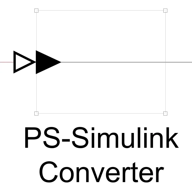
- PS simulink converter: It is used to convert physical signal to simulink signal.
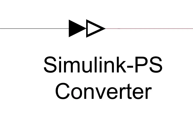
- Simulink PS converter: It is used to convert simulink input signals to physical output signal.
- Display: Used to see the output result.
- Scope: Used to observe the output for the simulation time.
- Pulse generator: Generates the pulse for specified interval and instance.
-
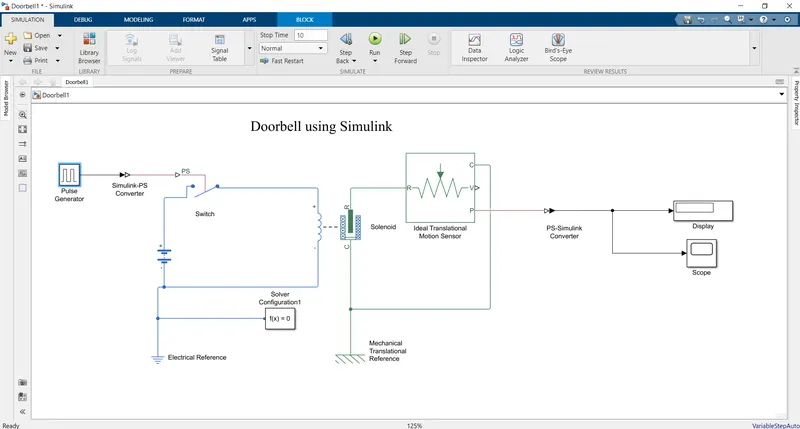
- The above schematic shows the model of doorbell in simulink.
- The doorbell is switched on for 2 sec.
- The pulse generator is used to simulate condition for the input to the switch, a Simulink PS converter is used to convert the signals.
- The battery is connected to supply the power to the solenoid when switched on.
- As the circuit is a electrical circuit Electrical reference is used.
- Solenoid is actuated by switching on/off the the switch provided.
- Solenoid movement is sensed/measured by the ideal translational motion sensor.
- The output of the motion sensor is given to the display and scope using the PS simulink converter to convert the signal from physical to simulink signal as the circuit gives the physical output.
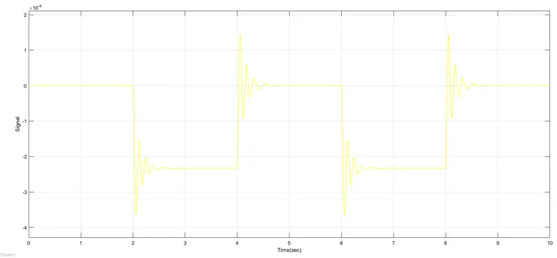
- The pulse generator is set to 50% of the width of 4 seconds with amplitude of 1 and phase delay of 2 seconds.
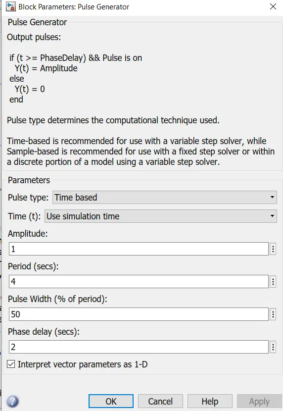
- The simulation time is set as 10 seconds.
- The output is observed in the display and the scope.
Part-2 Thermistor controlled fan:
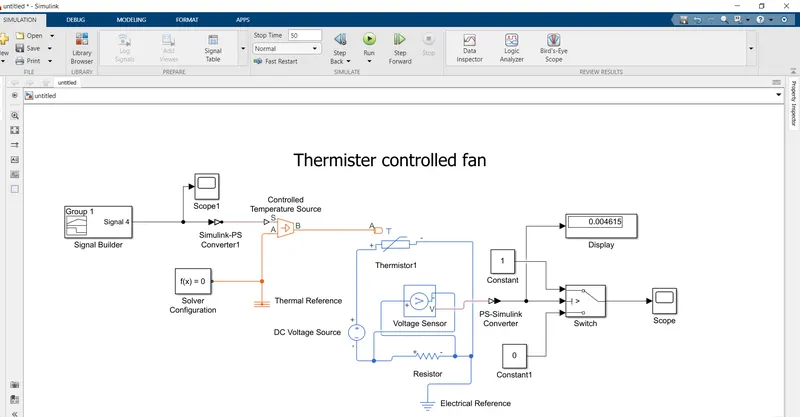
- The block diagram represents the simulation model of the Thermistor controlled fan:
-
- The blocks used here are:
- Signal builder.
- Scope.
- Controlled temperature source: Outputs the temperature based on the inputs given.
- Solver configuration.
- Thermal Reference: Reference value for the temperature (absolute zero).
- Thermistor.
- DC voltage source: Manintains constant DC voltage (5V).
- Voltage sensor: Used to measure the voltage difference, output is physical signal(V-port).
- Resistor: A linear resistor is used in the circuit with 1 ohms resistance.
- Electrical reference.
- Constant blocks: Used as the switch values 1-On and 0-OFF.
- Scope.
- Display.
- The signal builder is used to simulate the temperature variations with respect to time.
- Controlled temperature source uses the input of the Simulink PS converter from the signal builder to replicate the temperature values at the specified time intervals.
- Thermal reference is connected to measure from absolute zero.
- Thermistor is used to measure the temperature, here the resistance value changes with respect to the temperature, this is measured and the output physical signal is votlage difference measured by the voltage sensor connected in parallel.
- Electrical reference is connected to the circuit refered to as the electric ground.
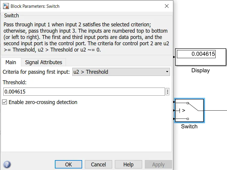
- Switch block is used to switch the fan ON/OFF by taking the voltage for the threshold limit(after this point the switch will flip) 1-port represents the ON value and 3-port represents OFF value and 2-port is the input (physical converted to simulink signal).
- To calculate the threshold the signal builder block is used with the 298.15 kelvin stright input and the voltage sensor value is noted from the display(0.004615).
- The output with respect to the tome is observed in the scope.
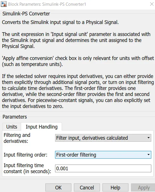
- The input handling the Simulink PS converter must be changed to Filter inputs, First order filtering and with input filtering time 0.001 seconds as shown.
Errors:
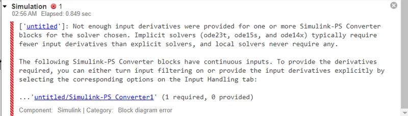
The above shown error can be solved by changing the input handling the Simulink PS converter must be changed to Filter inputs, First order filtering and with input filtering time 0.001 seconds as shown.
Results:
- The doorbell simulink model is run for 10 seconds.
- Output of the doorbell simulation in simulink:
- The simulation of the thermistor controlled fan is done with 50 seconds of simulation times.
- The output of the thermistor controlled fan simulation is:
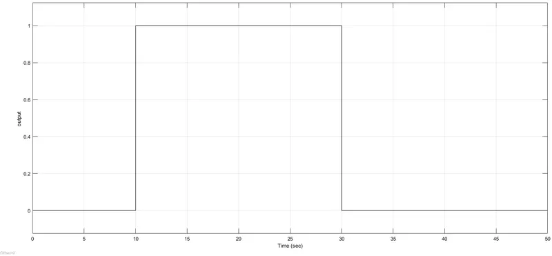
- Here output means ON/OFF
Conclusions:
- The doorbell simulation model is successfully executed and the results are plotted.
- The thermistor controlled fan model is simulated for 50 sec and the results are plotted.