Week 7 State of charge estimation
EV LIVE BATCH 21
1.Simulate the 3 test cases from harness dashboard and write a detailed report on the results
The harness dashboard to simulate the test cases is given as,
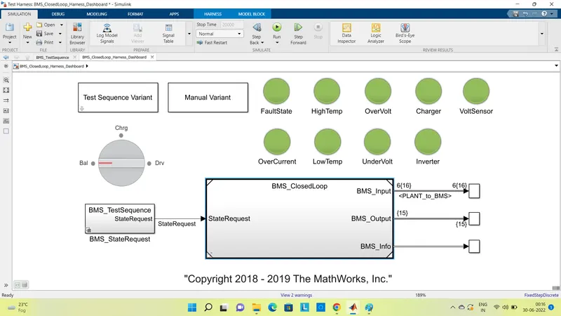
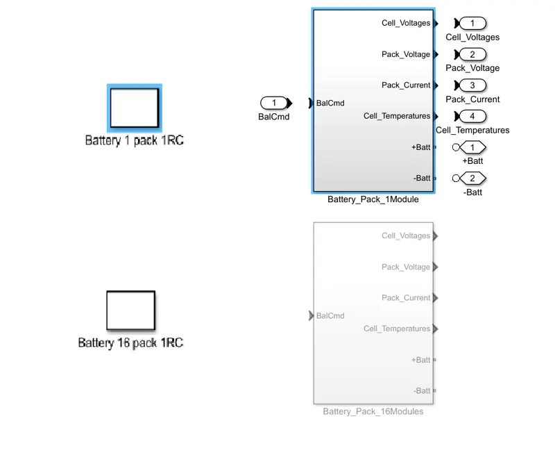
Now, for the simulation of BMS - Battery management system, we have 2 battery packs. One is having 1 module of battery pack consists of 6 cells and another has 16 modules, each consisting 6 cells i.e. 96 total cells. But for simplicity and fast responce of the model, here battery pack with 1 module og 6 cells is to be selected.
For that, open the BMS closed loop subsystem block, can be shown as,
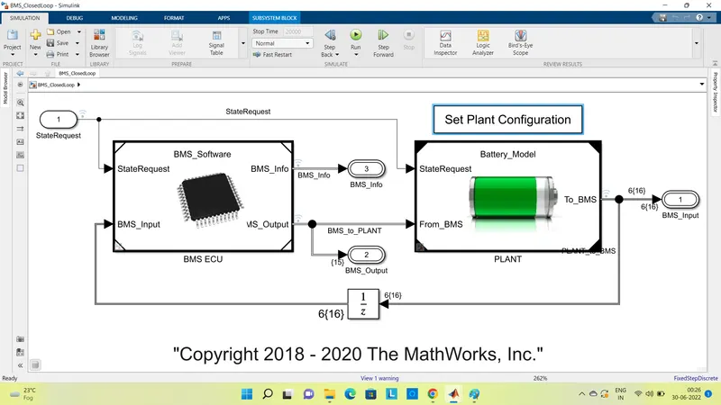
Here, battery pack can be selected as opting Set Plant Configuration block. With this selection, desired module of battery pack is selected consisting 6 cells.
Further more selection of the test case is done by configuring the subsytem Test Sequence Varient Block.
- For 1st Test Case,
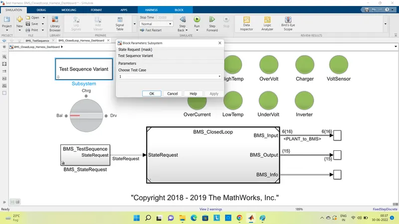
upon selecting first test case, BMS Test Sequence State request gets configured as,
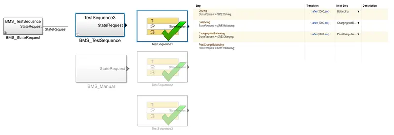
After setting up the test sequence and running the simulation, if All Harness Board parameters are indicating green that means there are no errors and system is good to go. So the results for test case one can be shown as,
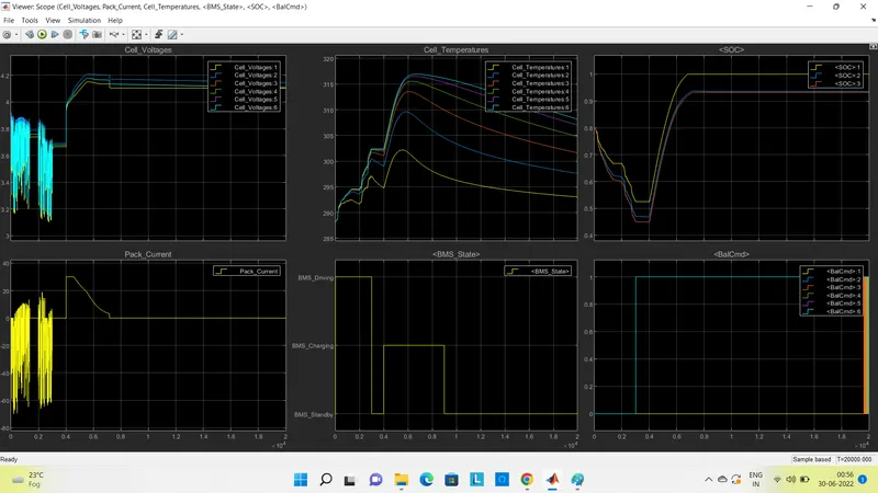
There are six result plots, cell voltage, cell temperature, SOC, Battery Pack Current, BMS state and cell Balancing.
Vehicle undergoes mainly 3 states, i.e. driving, charging and standby. This is represented by BMS state as input cycle for selected test case. Now, as per result plot it can be observed that,
for first 3000 sec vehicle is under driving state - cell voltage and current values are fluctuating, while temp is rising and SOC is droping upto 45% value. For next 1000 sec vehicle is in standby state - balancing of cell voltage is happening, Temp is falling and SOC is getting increased marginally. Furthermore next 5000 sec, vehicle is in charging state - Cells are getting charged upto almost 4.2 V, temp is again rising, so is the SOC, batteries are getting charged almost 100% of SOC. And After this time period Vehicle is again put to standby state. All the values of voltage, current, SOC, are getting stable and temp is dropping down gradually.
- For Test case 2,
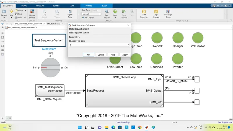
upon selecting test case 2, BMS Test Sequence State request gets configured as,
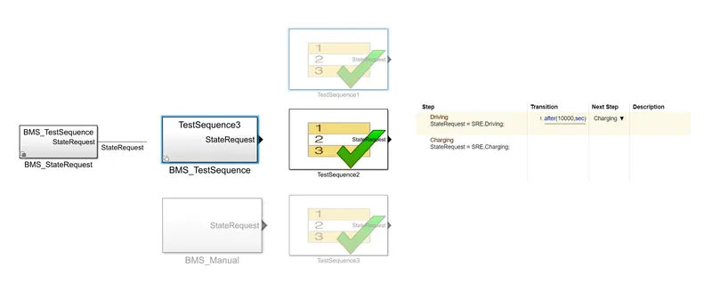
After running the Simulation, the results for test case one can be shown as,
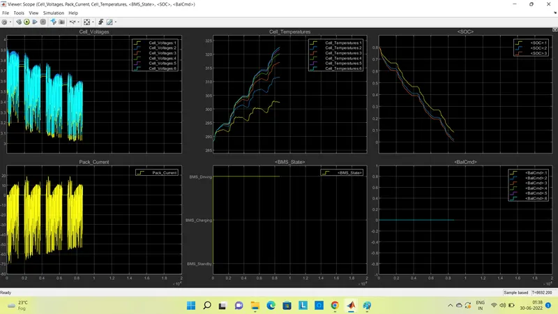
As per conditions stated in case 2, vehicle is in driving state for first 10000 sec. Accordingly results were getting obtained, SOC was dropping down and temp was rising but at near about 8500 sec, fault condition occured. So, vehicle stopped and went on stand by state. Hence for further charging state also, SOC is drained to almost 0% and cells are not getting charged. Also the voltage and current values of the cell has got stable constant values.
- For Test case 3,

upon selecting test case 2, BMS Test Sequence State request gets configured as,
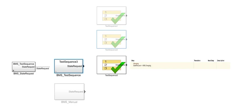
After running the Simulation, the results for test case one can be shown as,
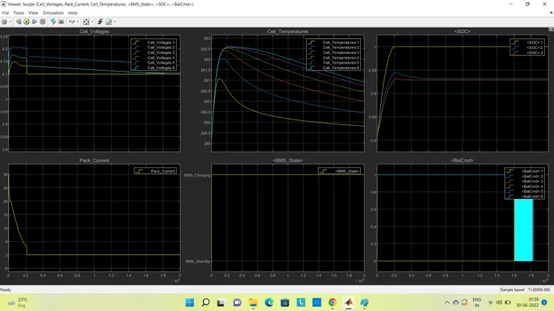
Here, vehicle is operating only under charging state. So battery will undergo peak current, peak voltage while charging, SOC is rising from 80% to 100%, Temp is also rising while charging. Once the battery obtains 100% od SOC, no further charging is possible. So BMS will operate as protection against overcharging, current gets cut off to zero, Temp will fall down gradually, SOC will remain stable at 100%.
2.What is coulomb counting? Refer to the above model and explain how BMS implements coulomb counting for SOC estimation ?
The battery is one of the most attractive energy storage systems because it has the advantages of high efficiency, high working cell voltage, low pollution, low self-discharge rate, and high power density. The SOC of a battery, which is used to describe its remaining capacity, is a very important parameter for a control strategy. In general, the SOC of a battery is defined as the ratio of its current capacity Q(t) to the nominal capacity Q(n)
SOC = Q(t)/Q(n)
As the SOC is an important parameter, which reflects the battery performance, so accurate estimation of the SOC can not only protect battery but prevent overdischarge and improve the battery life, also allow the application to make rational control strategies to save energy. So, one of the methode for SOC estimation is,
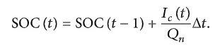
- Coulomb Counting Method : This method measures the discharging current of a battery and integrates the discharging current over time in order to estimate SOC. Coulomb counting method is done to estimate the SOC(t), which is estimated from the discharging current I(t) and previously estimated SOC values SOC(t-1). SOC is calculated by the equation,
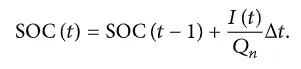
But there are several factors that affect the accuracy of Coulomb counting method including temperature, battery history, discharge current, and cycle life. So to improve the Coulomb counting method, a new technique called modified Coulomb counting method is proposed.
The modified Coulomb counting method uses the corrected current to improve the accuracy of estimation.The corrected current is the function of discharging current. There is a quadratic relationship between the corrected current and discharging current of battery. By practice of experimental data, corrected current is calculated by the following form,

where , k1, k2 and k3 are constant values obtained from the practice experimental data.
In modified Coulomb counting method, SOC is calculated by the following equation,
The experimental results show that the accuracy of the modified Coulomb counting method is superior to the conventional Coulomb counting method.
Now in the BMS model, Coulomb counting method is implemented for SOC estimation as, in the ECU subsystem of BMS, we can find a subsytem as SOC estimation subsystem.
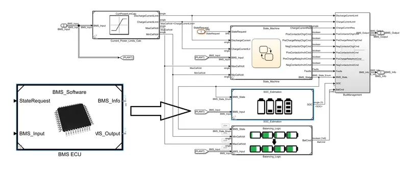
further more, explore the SOC estimation subsystem block, Coulomb Counting system is implemented. After clicking on that block, implementation of Coulomb Counting is given as,

Here, SOC is calculted as the equations mensioned above. Value of current and temp of battery are taken as input. Current I(c) is then multiplied with constant values K, by means of a gain block. While temp is given to the capacity block, as capacity varies with change in temp. The ratio of these two values estimated the previous state of SOC. This value then is integrated, to get the current SOC, with respect to time. Hence final SOC is estimated for the current state.