Week-7 Challenge: DC Motor Control
EV LIVE BATCH 21
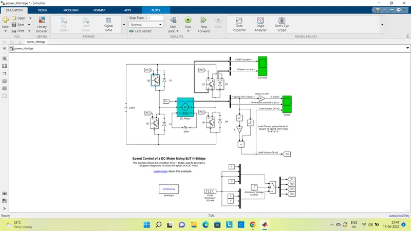
1. A. Explain a MATLAB demo model named ‘Speed control of a DC motor using BJT H-bridge’.
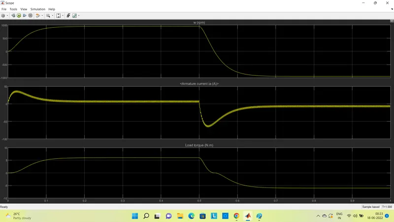
B. Comment on the armature current shoot-up from the scope results.
If we consider only the converter switching circuit for the motor, it can be simply given as,
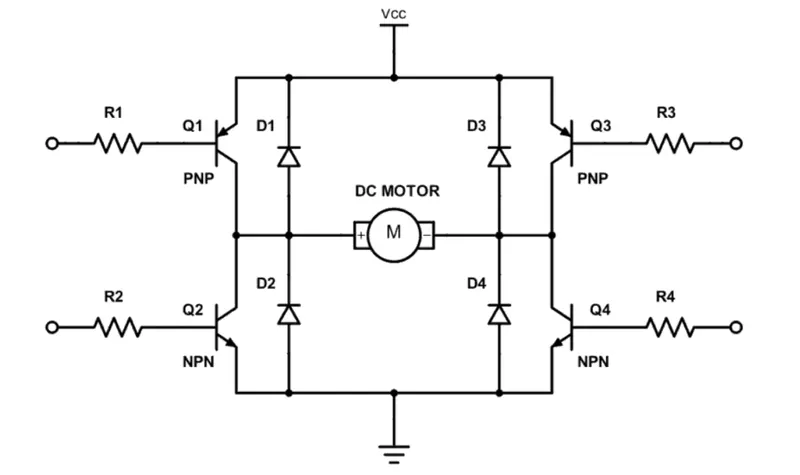
It is called as BJT H-Bridge because it uses BJTs as switching devices and forms a H-shaped bridge to control the DC motor associated. here, Q1, Q2, Q3, Q4 are BJTs and D1,D2,D3, D4 are free-wheeling diodes used.
The BJTs when used for power switching applications, operates as an IGBT. When it is conducting, a forward voltage Vf is developed between collector and emitter. Therefore, the IGBT block can be used to model the BJT device.
now when Q1 and Q4 are closed, a positive voltage is applied to the motor, then current will flow from +Ve – Q1 – MOTOR – Q4 – Gnd. So motor will rotate in say, Forward direction. Open Q1 and Q4 to stop the motor and diodes D2-D3 operate as free-wheeling diodes.
Similarly, when Q2 and Q3 are closed, a negative voltage is applied to the motor and current will flow from +Ve – Q3 – MOTOR – Q3 – Gnd. So motor gets reverse supply and it will rotate in reverse direction. Diodes D1-D4 operate as free-wheeling diodes when Q2 and Q3 are switched off.
After running the simulation, results obtained are,
For DC motor, armature current Ia can be given as,
Ia = (V - Eb)/Ra, where V - supply voltage, Eb - back EMF, Ra - armature resistance,
so, at the time of starting, Eb = 0, so Ia value will be more.
that is why we can observe a boost in armature current at the time of starting where speed of the motor is also less and then increasing gradually, with increase in speed, Eb can be generated and Ia value gets reduced.
Also, when polarity of the supply is reversed, at T=0.5sec, motor speed starts reducing rapidly and will rotate in the reverse direction giving negative values. At that time also, armature current boost can be observed giving negative value as the direction of flow is reversed. This results are obtained at the pulse width of 75%.
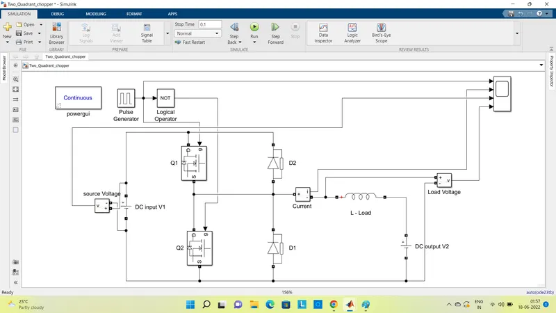
2. Develop a 2-quadrant chopper using simulink & explain the working of the same with the relevant results. (Refer to article - Multiquadrant operation of motor )
the above circuit can be simplified as,
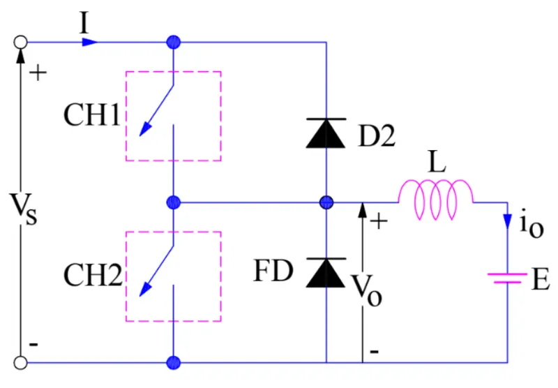
Here, CH1 and CH2 represents switching MOSFETs Q1 and Q2 used in the model. whereas FD(D1) and D2 are free-wheeling diodes.
Input voltage V1 is 24V and output voltage V2 represents back EMF produced by the motor and is set at 12V.
The values for pulse generator are set as, period = 0.02 sec, and pulse width = 50%. this signal is given to Q1 directly. but for Q2 it is fed via a NOT logical operator, so that both the switches will operate one after another and not at a time, i.e. when Q1 is conducting, Q2 will not operate and vice-versa.
Now, when Q1 i.e. CH1 is closed, source Vs directly gets connected to the load and hence, load voltage Vo is equal to source voltage. The direction of load current is from source to load which is assumed positive. When CH1 opened, the free-wheeling diode FD comes into the circuit as it gets forward biased and hence shorts the load. Therefore, the output voltage Vo becomes zero. However, the io continues to die down through the FD and L in the same direction. Thus, the average output voltage Vo and current Io are positive and hence operation of chopper is in first quadrant.
When Q2 i.e. CH2 is closed, load DC source E drives current through CH2 and load. The direction of this current io will be opposite hence is assumed negative. Output voltage Vo is zero during this time. When CH2 is made open, diode D2 gets forward biased and hence the current flow is from load to the source. The output voltage is Vs in this time as the load is connected to the source through D2. Thus, as the load current is negative i.e. operation of chopper is in second quadrant.
The result of the simulation can be obtained as,
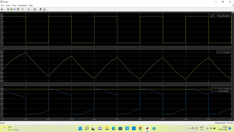
Hence we can observe that, the load voltage is always positive but the load current may be positive or negative. Therefore, power may flow from source to load (first quadrant operation) or load to source (second quadrant operation).
3. Explain in a brief about operation of BLDC motor.
A BLDC motor is a permanent magnet synchronous electric motor which is driven by DC voltage and it accomplishes electronically controlled commutation system i.e. producing rotational torque in the motor by changing phase currents through it at appropriate times.
BLDC motor consists of two main parts a stator and a rotor. Permanent magnets are mounted on the rotor of a BLDC motor, and the stator is wound for a specific number of poles. Also, a control circuit is connected to the stator winding. Most of the times, the inverter/control circuit or controller is integrated into the stator assembly. This is the basic constructional difference between a brushless motor and a typical dc motor.
A typical controller provides a three-phase frequency-controlled supply to the stator winding. The supply is controlled by logical control circuits and energizes specific stator poles at a specific point of time. This can be understood from the below animations about working of BLDC motors.
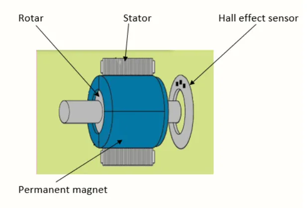
BLDC motor works on the principle of Lorentz force law which states that whenever a current carrying conductor placed in a magnetic field it experiences a force. As a consequence of reaction force, the magnet will experience an equal and opposite force. In the BLDC motor, the current carrying conductor is stationary and the permanent magnet is moving.
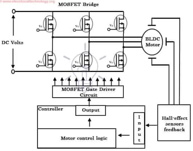
The electronic controller circuit energizes appropriate motor winding by turning transistor or other solid state switches to rotate the motor continuously. The figure shows the simple BLDC motor drive circuit which consists of MOSFET bridge (also called as inverter bridge), electronic controller, hall effect sensor and BLDC motor.
Here, Hall-effect sensors are used for position and speed feedback. The electronic controller can be a microcontroller or microprocessor. This controller receives these signals, processes them and sends the control signals to the MOSFET driver circuit. In addition to the switching for a rated speed of the motor, additional electronic circuitry changes the motor speed based on required application. These speed control units are generally implemented with PID controller to have precise control.
Advantages of BLDC,
- Less overall maintenanceand low noise due to absence of brushes
- Higher speed range and lower electric noise generation.
- It has no mechanical commutator and associated problems
- High efficiency and high output power to size ratio due to the use of permanent magnet rotor
- High speed of operation even in loaded and unloaded conditions due to the absence of brushes that limits the speed
- Smaller motor geometry and lighter in weight than both brushed type DC and induction AC motors.
- Long life as no inspection and maintenance is required for commutator system
- Higher dynamic response due to low inertia and carrying windings in the stator
- Less electromagnetic interference
- Reduced size with far superior thermal characteristics