Week 7 State of charge estimation
Note-This is live EV Batch 2
Ans-1:-
Harness dashboard-
- The close loop harness dashboard model is as below-
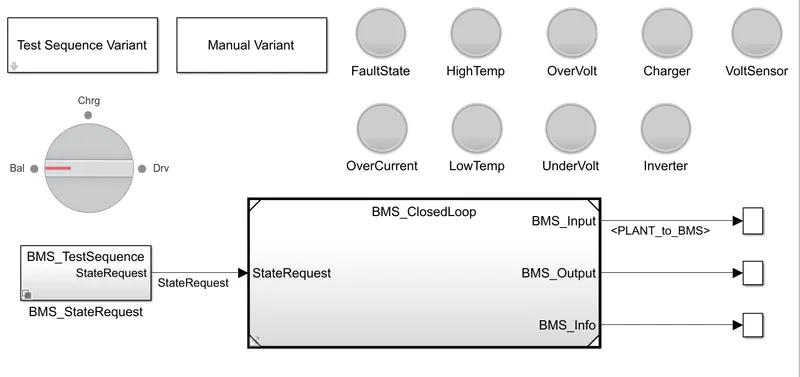
- There are three test sequence varient which can open by test sequence varient as circled by red colour.
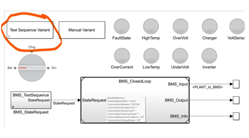
- By double clicking on test sequence varient,a new window will open as shown below .From where we can open test cases.
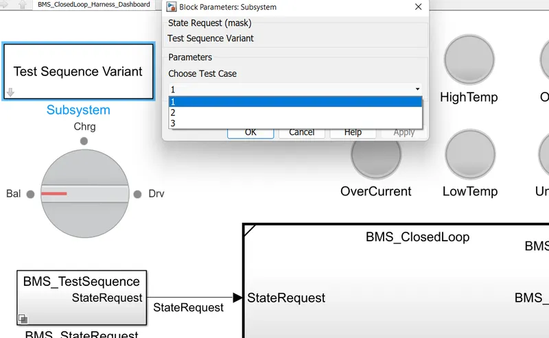
- By selecting the test case 1 condition-
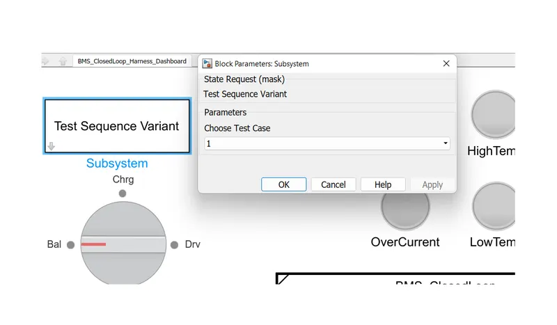
The condition are shown below as the simulation starts with driving condition after 3000 sec ,it will be in balancing mode and after 1000 sec ,it will be in charging and balancing mode and after 5000 sec of this post charging balancing mode will happen.
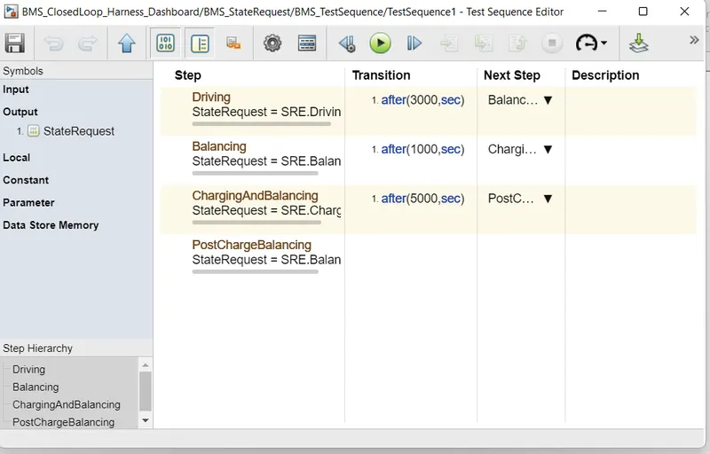
- After selecting the test case varient 1,and run the simulation for 20000 sec-
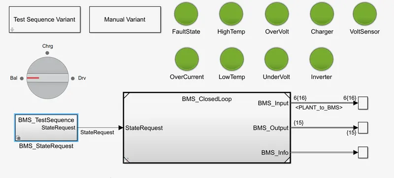
as we can see the there is no error coming.as each lamp shows green thats means green shows no error and red colour shows error in simulation.
OUTPUT for test 1-
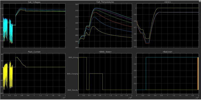
As per our condition given ,from 0 to 3000sec vehicle is in driving condition(Observed from BMS state),so vehicle will use power thats is taken by battery so SOC label is going(from 80% to 40%)down from 0 to 3000sec.As the pack current shows the current provided to vehicle.During driving and charging mode,the temperature of cell rises.
From 3000sec to 4000sec,this is battery balancing mode.In which the temperature has no more variation ,SOC is constant and supply current and voltage is constant.
From 4000sec to 9000sec,this is charging and balancing mode.So we can see that during charging ,the SOC of battery is increasing from 40% to 100%.And cell voltage is also increasing .
From 9000sec to simulation time (20000sec),the vehicle is in stand by mode ,so there is no use of power,So SOC label is constant and cell temperature is constant.As there are no demand of power so current value goes to zero.
- By selecting the test case 2 condition-
By choosing test case 2 as shown below image.
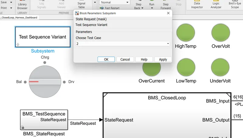
- Conditon of this state is as-
- It starts from driving condition which continuous to 10000sec and after that charging step comes.
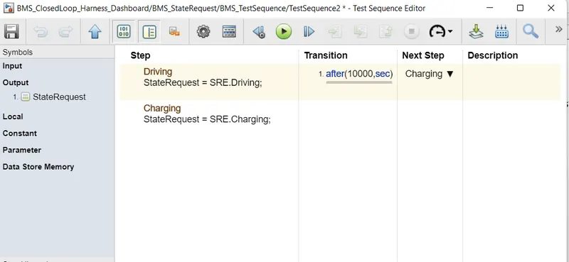
- After simulation-
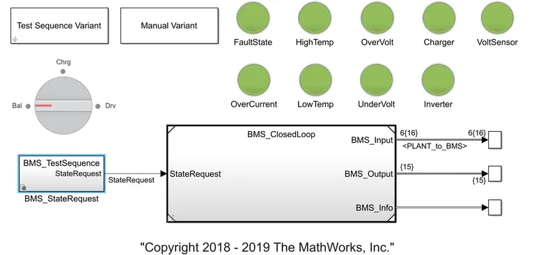
All are shows green signal, which means no error.
OUTPUT for test 2-
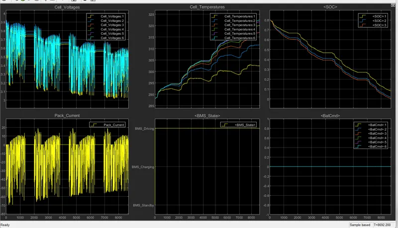
As per condition the vehicle is in driving mode so the SOC label of battery is continuously decreasing and temperature is increasing as battery is using.
As we can see that total simulation time is 8962sec.At this time the SOC label is at 0% . As per our condition charging step can not be achieved beacuse it happens after 10000sec.
hence the vehicle comes in stand by mode and simulation stop in midway.
- By selecting the test case 3 condition-
By choosing test case 3 as shown below image.
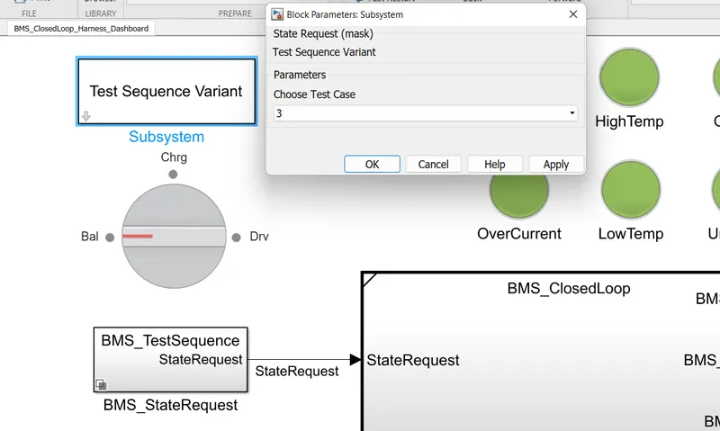
Condition for this state is only charging happens all time.
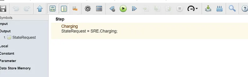
- After simulation-
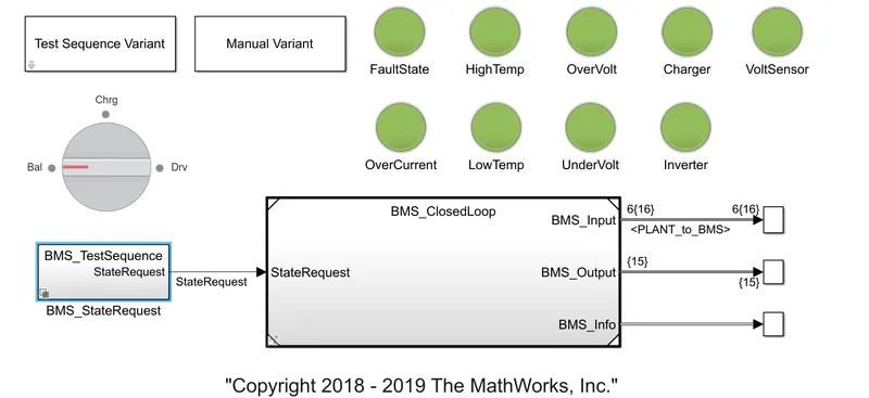
All are shows green signal, which means no error.
OUTPUT for test 3-
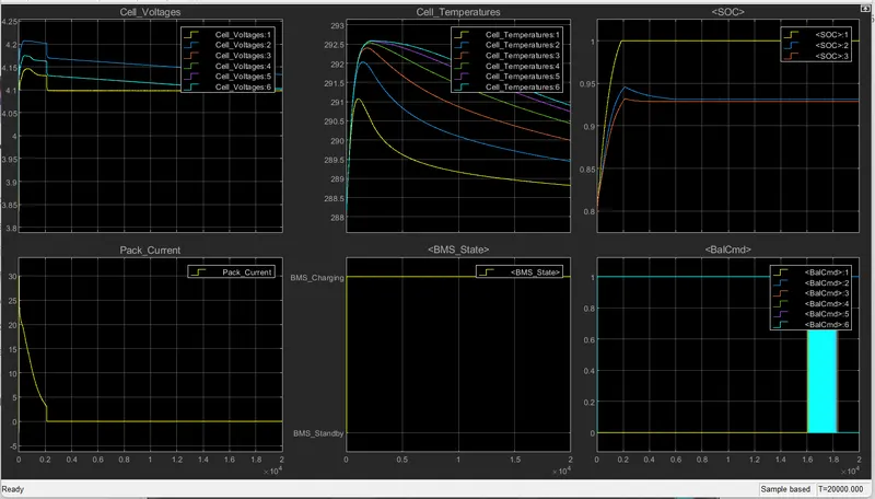
As from the graph it is clear that charging step is happen only .The SOC label is increasing from starting till 2000sec and after being charged 100% ,remains constant as charge is not used anywhere.As in this test,there is no driving happens so current supply is at 0.
Ans-2:-
Coulomb counting-
Coulomb counting is a technique used to track the state of charge of a battery pack. It works by integrating the active flowing current (measured in amps) over time to derive the total sum of energy entering or leaving the battery pack. This produces a capacity that is typically measured in Amp-hours.
Formula for Coulomb counting is as-
To improve the Coulomb counting method, a new technique called modified Coulomb counting method is proposed. The modified Coulomb counting method uses the corrected current to improve the accuracy of estimation.
The corrected current is the function of discharging current. There is a quadratic relationship between the corrected current and discharging current of battery. By practice of experimental data, corrected current is calculated by the following form:
Ic(t)=k2I(t)2+k1I(t)+k0
where k2,k1 and k0are constant values obtained from the practice experimental data.
In modified Coulomb counting method, SOC is calculated by the following equation:
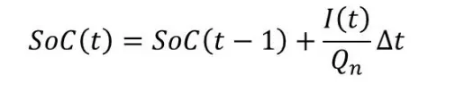
The experimental results show that the accuracy of the modified Coulomb counting method is superior to the conventional Coulomb counting method.
- By giving model we can calculate SOC by Coulomb counting method by using BMS close loop model-
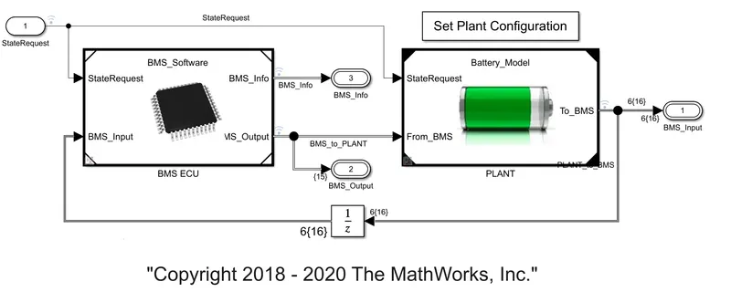
- BY double clicking or opening the BMS ECU,a new window will open as below-
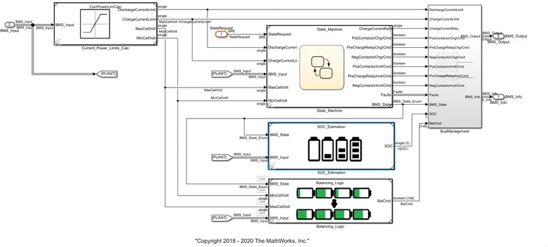
- Now by opening SOC_Estimation block-
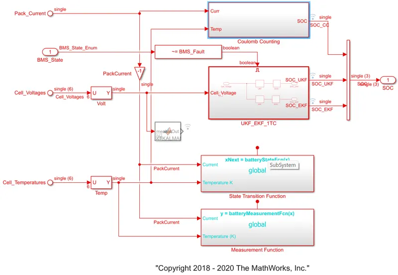
- Here we can see that on above ,there is a Coulomb counting block .By opening this block-
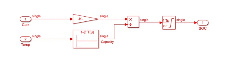
The above model used the same equation which is shown above.Here the Coulomb counting method is used as mathematical model shown above.
Here current and temperature is taken from battery.Current is given to gain block and temperature is given to capacity which varries according to temperature.Both the inputs are given to intregator where current will integrated with respect to time.
This output is given to other block where it is divided by capacity which gives the value of SOC.