Week -2
Ans-1:Door Bell-
Simulink Model:-
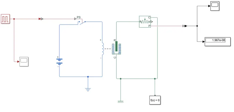
Solenoid:-
A solenoid is electro mechanical device in which passing current through wire, generates magnetic field which attracts the magnetic material(plunger is made of magnetic material) which cause the hit on bell which produces sound.
Explanation:-
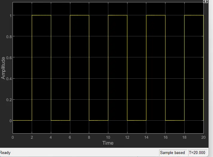
1>Pulse generator is used for building the required wave as input signal of amplitude=1,phase delay=2sec,period=4sec,and pulse width=50% .For t=20sec the plot is as follows.
2>After that input signal is converted into physical signal using Simulink-PS converter and send to switch.
3>Then one part of switch is connected to solenoidal and further to battery .Battery and switc forms a current hense a electric reference is connected.
4>The mechanical part of solenoid is connected to 'ideal translation motion sensor' and mechanical translation reference.
5>As solenoid is electo mechanical component when pulse is send through pulse generator,switch gets activated which creats close loop conection and battry got a full conection , a signal is created into loop.When the signal goes through solenoid in electric part , a magnetic zone is created in mechanical part which attracts the plunger .Ans plunger position is fitted in the way that it hit the ring which creats the ring.
6>A solver configuration is connected to circuit to solve all parameters before the beginning of simulation.A mechanical reference is also connected with mechanical part of solenoid.
7>To see the result ,as it is mechanical part , we have to connect the PS-simulink converter ans finally connect to scope and display.
OUTPUT:-
The output waveform is showing below compare to input data-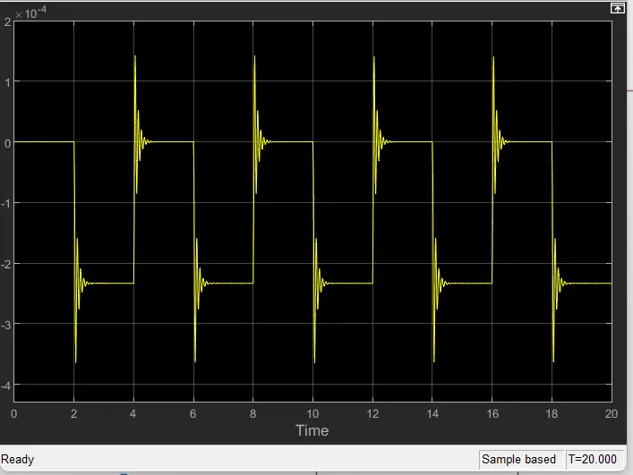
Ans-2:-
Thermistor-
Thermistor is made of two words 'thermal' and 'resistor'. So it can be defined as the resistor valve of the thermistor is depend on temperature. As temprature changes ,the resistor value also changes.
Simulink Model:-
Simulink model of thermistor is as follows-
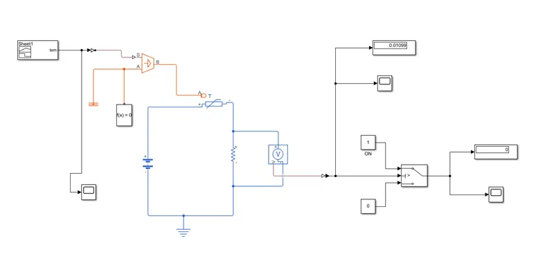
1>As from given condition the signal builder will generate signal as follows-
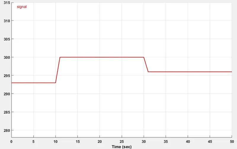
2>The signal builder is connected to the the controlled temperature source.Which is provide specific heat to the system.
3>To maintain the thermal difference a theremal reference is also added.
4>A battery is connected with thermistor and a resistor is connected to negative terminal of thermistor.Across the resistor a Voltage sensor is used to measure the voltage as a threshould value for condition of the circuit.
5>For switch ON or switch OFF the fan condition,a switch is used and provide the threshould value.Switch will 'ON',when the output of voltage sensor is greater than threshould value and 'OFF',when it less.
6>The threshould value is as follows.
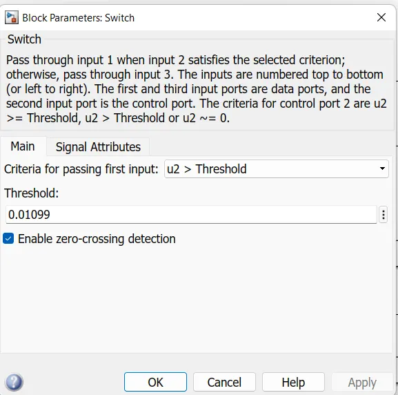
Scope and display is used to see the output.
Results:-
The output from the scope is as follows-
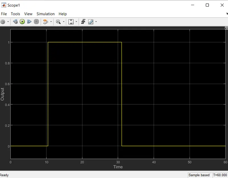
From 0 to 10 sec ,switch is in OFF condition because the the temperature is below 25 degree celcius and remain from30 to 60 sec.And switch is in ON condition from 10 to 30 sec as temperature is greater than 25 degree celcius (as according to given condition).