Week - 4
Ans-01:
Theory:
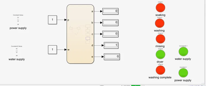
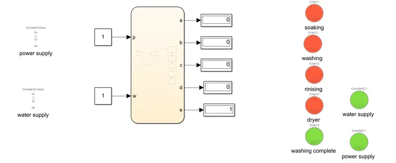
As in the simulink two toggle switch is used.One for power supply and another for water supply.
Two constant block for input which is connected to both switch.A chart for control logic and display for output which is connect to lamp.RED indicated the OFF condition and GREEN indicates the ON condition.
Stateflow:
According to given condtion,we have to implement control logic for washing machine using stateflow.
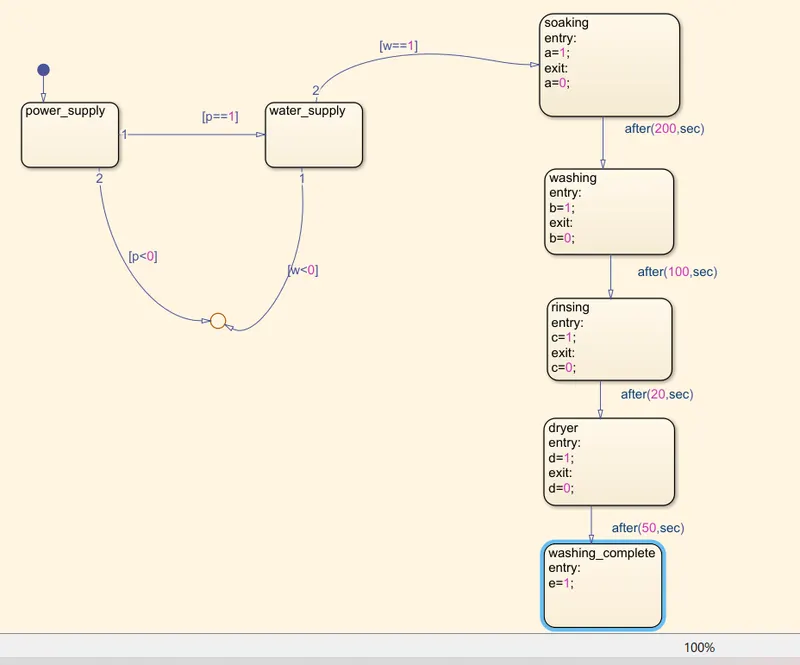
1>As if the power supply is ON(p==1) condition,then it will go for next step and if it is OFF(p<0)condition,it simply go to a state i.e. will not go to next step.
2>As if the power condition is ON,then next step will happen which is checking of water supply.
if water suppy is on condition (w==1),then next step will happen and if water supply is OFF (w<0)then there will be a message through LED and next step will not happen.
3>If power and water supply both is in ON condition then it will go for soaking .There is use a time delay of 200sec that means till that time soaking will happen.After soaking,washing operation will happen till 100sec after that rinsing for 20sec and in last dryer for 50sec.
4>After dryer washing process will be complete.
Here p and w is used as input port and a,b,c,d and e is used as output port.
OUTPUT:
The step wise result be as follows.
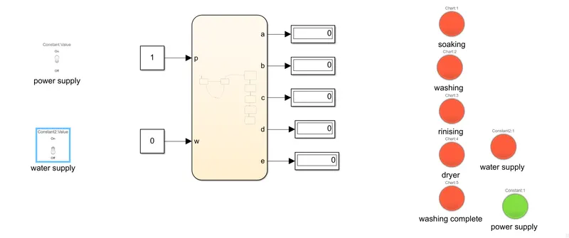
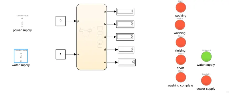
RED lamp shows OFF condition.
GREEN lamp shows ON condition.
1>When power supply is ON(p=1)and water supply is OFF(w=0);
2>When power supply is OFF(p=0)and water supply is ON(w=1);
3>When power supply is ON(p=1)and water supply is ON(w=1);
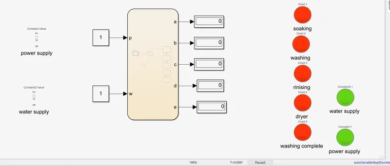
4>Soaking
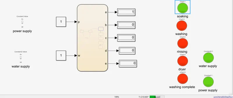
5>washing-
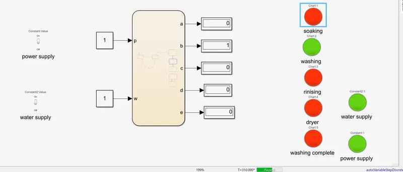
6>Rinising-
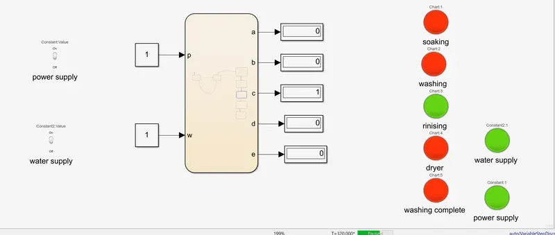
7>Dry
8>washing complete
Ans-02-
Model of Gear Shift Logic-
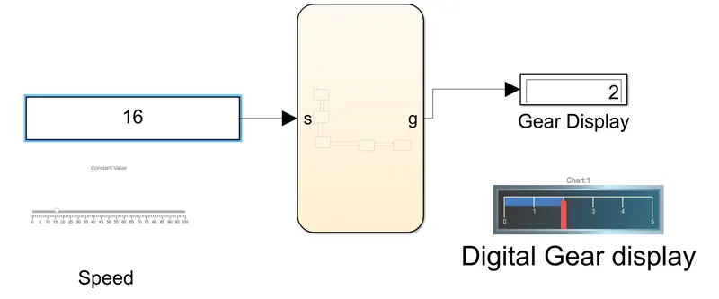
As in the model the speed value is given via either constant block or with the help of speed slider.Chart is use for logic control and for output, display block is used.There is also a digital display is used to see the gear number.
Stateflow:
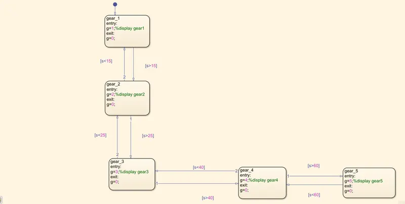
As there is one input as speed denoted as 's' and one output as gear number denoted as 'g'.
There is certain condition as below
if speed<15, then gear 1 will show.
speed<25, then gear 2 will show.
speed<40, then gear 3 will show.
speed<60, then gear 4 will show.
speed>60, then gear 5 will show.
OUtPUT:
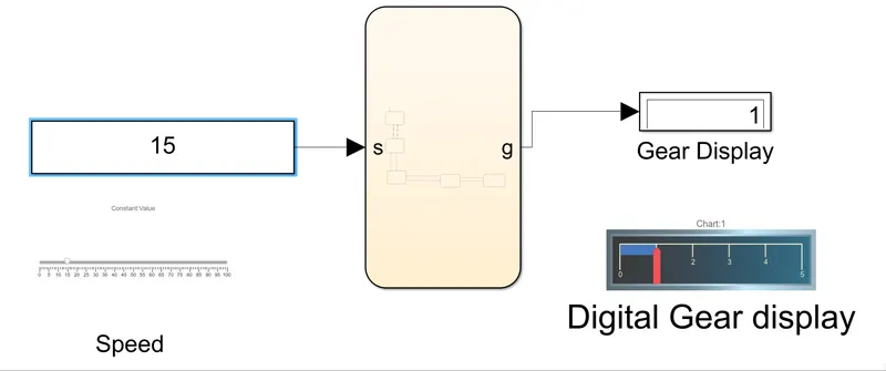
By giving different speed the gear result is shown bellow through model.
1>when speed is between 0 to 15.
2>when speed is between 16 to 25.
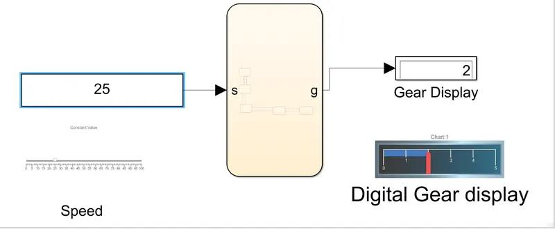
3>when speed is between 26 to 40.
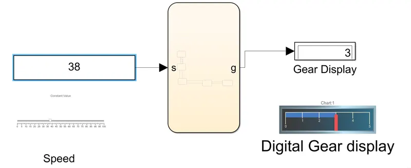
4>when speed is between 41 to 60.
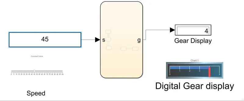
5>when speed is above 61.
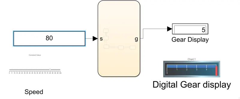
So by giving different input as speed ,we can obtain different gear number which can see on display.