Week 7 State of charge estimation
1. Objective: To simulate the 3 test cases from harness dashboard for battery management system closed loop model and to write detailed report on the results.
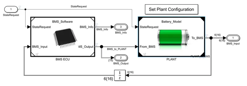
The following figure shows the BMS closed loop model consisting of BMS electronic control unit and plant:
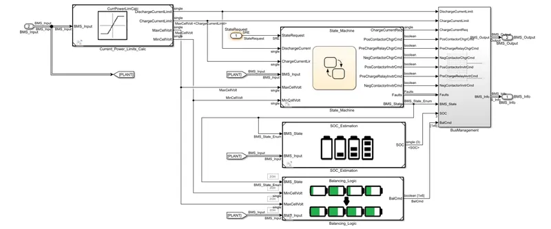
The subsystem of BMS ECU where it mainly comprises of state machine, SOC estimation and Balancing logic as shown in below figure:
The subsystem of comprises of battery pack, precharge circuit and charger & load systems as shown in the below figures.
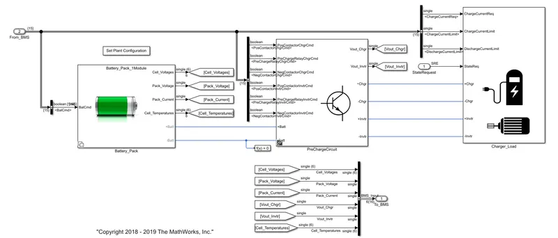
In the battery pack consists of two variants where one is consisting of one module in which six cells are connected and other one is consisting of this type of 16 modules connected in series. Here, only first variant i.e, only one module is considered for simulation.
The following figure shows the 'harness dashboard' from which we can apply various test sequences and observes status of the battery through LEDs:
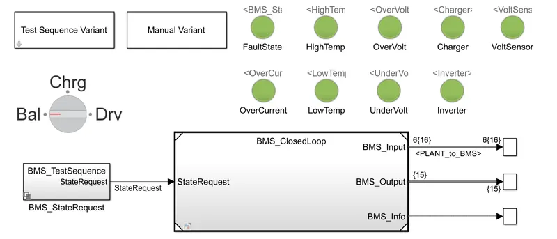
In dashboard, if any one of the LEDs glow in red colour, which resembles a fault occured in the battery pack.
TEST CASE 1:
Here, the model is scheduled to run in 'driving state' for first 3000 seconds, 'balancing state' for next 1000 seconds, 'charge and balancing state' for next 5000 seconds and 'post charge balancing state' for remaining time of about 11000 seconds which accounts to total simulation time for 20,000 seconds.

The following picture shows the results observed after simulating the model with test case 1:
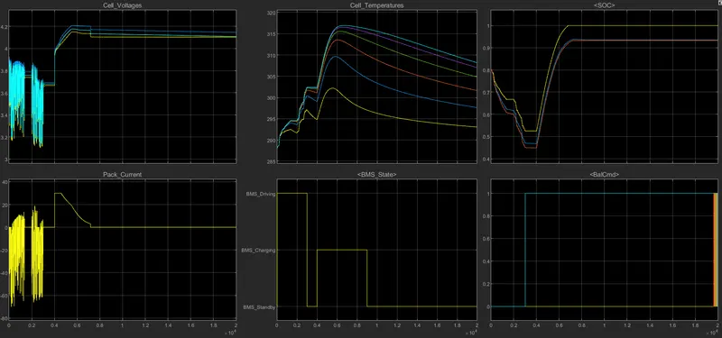
- Here, for first 3000 seconds, the model is drivng state, we can observe that the cell voltages are dropping while current is flowing out of the battery (& vice-versa) and temperature of them are raising and their SOC is falling.
- For next 1000 seconds, the model is running in 'balancing mode', where the voltages and currents of all cells are almost constant, but the balance command is given for cell no. 6.
- For next 5000 seconds, the battery pack is in 'charging mode', initially constant current charging followed by constant voltage charging happened.
- For remaining time of simulation, the battery pack is in 'post charge balancing mode' where the cell monitoring unit forces the cells with higher potential discharges through resistors (which is known as passive balancing) and tries to make all the cells with equal potential.
TEST CASE 2:
Here, the model is scheduled to run for 10000 seconds in 'driving state' and for another 10000 seconds in 'charging mode'.

The following picture shows the results observed after simulating the model with test case 2:
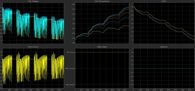
- Here, the model is schedule to run in driving state for first 10000 seconds followed by charging state for another 10000 seconds.
- The SOC and potential of the cell decreases while the current is flowing out of the battery and slightly increased while current is flowing into the battery i.e, during regenerative braking.
- But the model stops simulating at around 8700 seconds because there is no charge left in the cells i.e, thier SOC reached to 0%.
- Even if one cell is reached to zero SOC, the battery pack couldn't discharge anymore as all cells are connected in series.
- As the battery is in drivnig mode for more time, the cell temperatures increased widely.
TEST CASE 3:
Here,the model is schedule to run only in 'charging state' throughout the total simulation time i.e, 20000 seconds.

The following picture shows the results observed after simulating the model with test case 3:
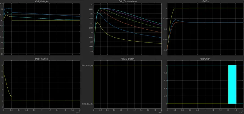
- Here, the model continously runs in charging state for throughout 20,000 seconds.
- Constant current charging couldn't takes place because the cell potential is almost close to 4.2 volts. So only constant voltage charging happened until the cells are fully charged.
- Even if one of the cell reaches to 100% SOC, the battery pack stops charging as the six cells are connected in series.
- As soon as the pack stops charging, the temperature of the cells gradually decreases.
- At the end, balance commands are applied to the cells with higher potential, so passive balancing carries out to those cells and the cell voltages are made almost equal.
2). Coulomb Counting:
- It means counting the amount of charge (in coulombs) entering in or out of the battery.
- It is one of the way to estimate the SOC (State Of Charge) of the battery.
- For example, if a battery is fully charged and it is in discharge state for x hours then total out flow of charge can be estimated by measuring the current of battery multiplying with total time in seconds at every second of the simulation. As the total capacity of the battery is already known in Ah, then removed charge interms of total capacity gives the percentage of charge removed. Similarly, SOC is estimated during charging state of the battery.
The following figure shows the block diagram for coulomb counting in battery management system model.
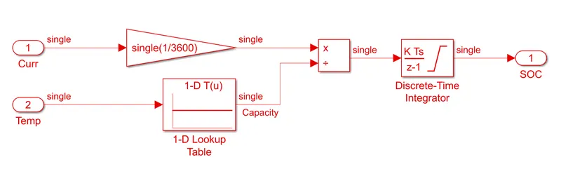
- Here, current and temperature are taken as inputs for SOC estimation through coulomb counting technique.
- The following explaination may not be according to the order considered in the above diagram but at the end, both gives out the same result.
- The discrete-time integrator block integrates the battery's current (or calculates area under the curve of current vs time) which result in the calculation of Ampere-seconds.
- A gain block of value '1/3600' is applied to the current to convert the Ampere-seconds to Ampere-hours.
- Now, you may be wonder why the temperature is considered for the calculation of capacity. Because the lithium ion battery's capacity varies with the temperature as shown in the following figure from datasheet of cell.
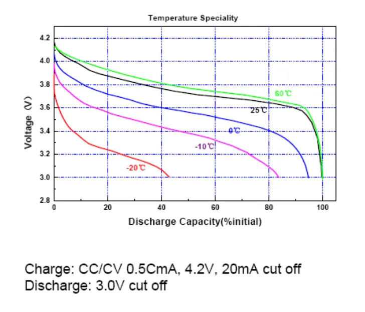
- Note: Above picture is displayed just to know relation between temperauture vs capacity and it is not related to the cells designed in the above model.
- So, the capacity of the battery is estimated using 'look up table' according to the temperature of the battery pack.
- As mentioned above, the net charge in Ah is calculated which is now divided by the capacity corresponding to the pack's temperature which gives out the net charge removed interms of total capacity.
- Now, if we substract this value with initial state of charge, then it results in the current value of SOC.