Week -2
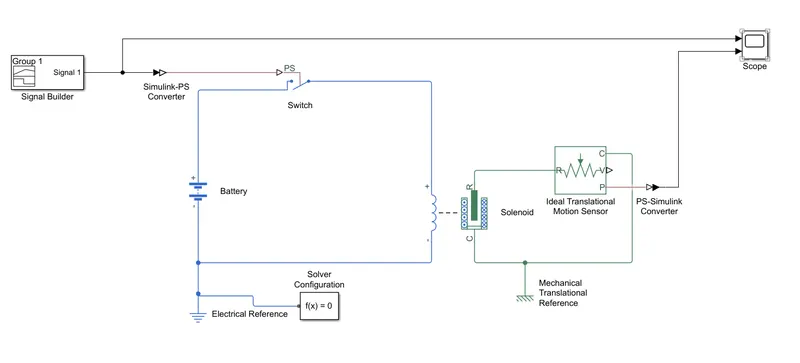
1). Aim : To build a simulink model for door bell mechanism using solenoid block.
Simulink model:
Various blocks are connected to create our required model as shown in following figure.
Control of switch :
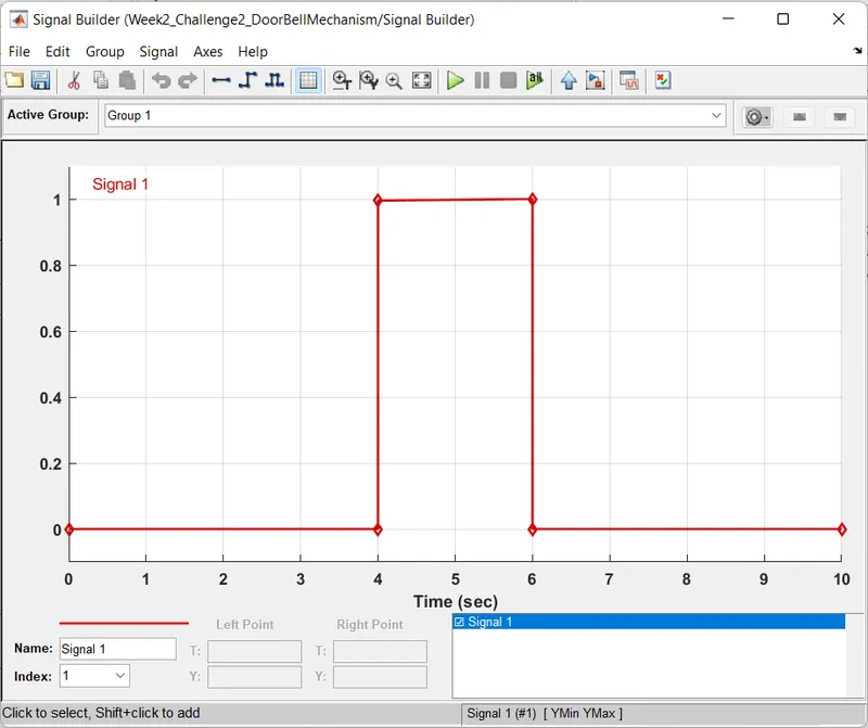
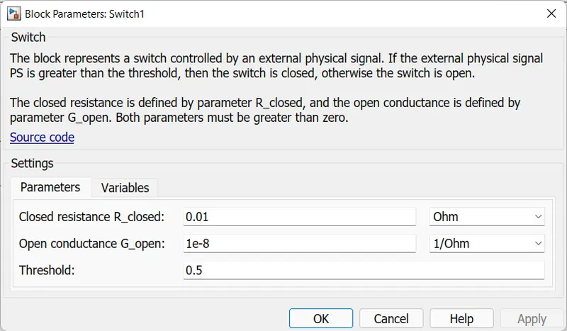
As described in the question that switch has to be in closed position for two seconds, so the physical sinal created in the signal builder has unit amplitude from 4th to 6th second, so at that time, amplitude of signal is greater than threshold (0.5) of the switch so that results in closing position of switch during that period of time and at all other time, the physical signal's amplitude is less than the threshold of the switch that results in open position of switch.
Results:
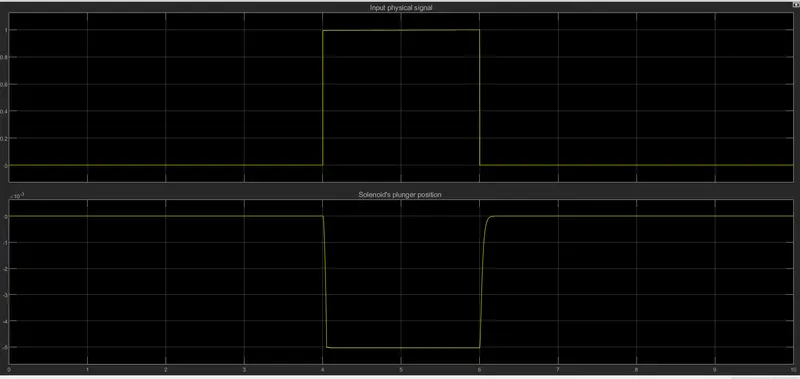
i. During 1st to 4th second, the switch is in open position, so the plunger didn't move from its position as no current flown through the solenoid.
ii. During 4th to 6th second, the battery voltage is applied across the solenoid, then magnetic field is created around the solenoid due to flow of current through solenoid, then the plunger experiences a force due to linkages of magnetic flux, so that plunger was displaced from it's position of about 5mm in negative direction that can be seen in scope which is sensed using translational motion sensor.
iii. During 6th to 10th second, the switch is in open position, no current flows through solenoid, so the magnetic field around it vanishes that leads to plunger to move back to its initial position due to its spring.
Note : The simulink file of the above problem is attached below.
2). Aim: To turn ON fan automatically whenever temperature exceeds the predefined value where temperature is sensed using thermistor.
Simulink model :
Various blocks are used to design this model as shown in below figure:
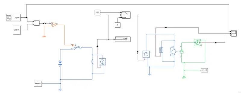
Temperature sensing through thermistor :
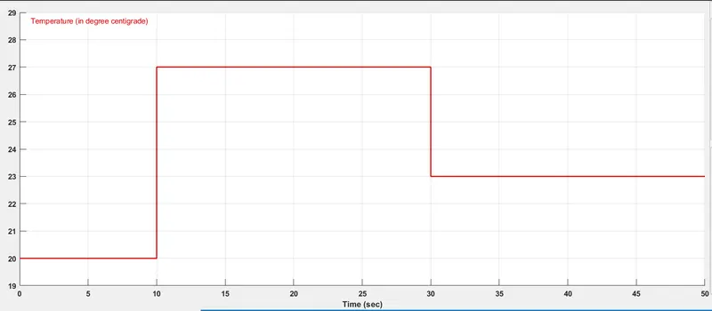
Initiallly, temperature signal/pattern is created in signal builder block as per given information in the question. As the default temperature parameters in thermistor are in Kelvin, so inorder to convert the temperature from celsius to kelvin, a constant of 273.15 is added to the temperature signal before passing it through controlled temperature whose output is given to terminal 'A'of thermistor that enables thermistor to sense temperature and inturn it offers resistance against the sensed temperature. Here, the thermistor is used of NTC (negative temperature coefficient) type, so resistance offered by thermistor decreases when the temperature sensed by it increases and viceversa.
Control of switch :
A battery of 12V is connected in series with thermistor and resistor. As temperature increases, the voltage across the thermistor decreases due to the decrement of resistance offered by it which inturn increases the voltage across the resistor. In our model, the fan should turn ON when the temperature exceeds 25°C, so we will measure the voltage across resistor at 25°C that value is given as threshold for the switch that is controlling motor/fan.
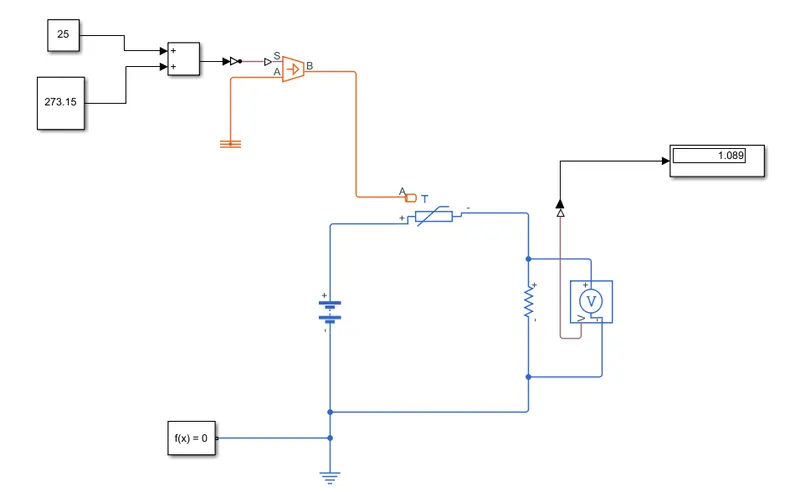
As shown in above figure, the voltage across resistor is 1.089volts at 25°C. When temperature exceeds 25°C, the voltage across the resistor will be greater than 1.089V. As this value is given as threshold for switch, it will give output as 200 whenever temperature exceeds 25°C or else its output will be zero. These output constant signals (either 220 or 0) are given to controlled voltage source whose voltage is applied across the fan's motor.
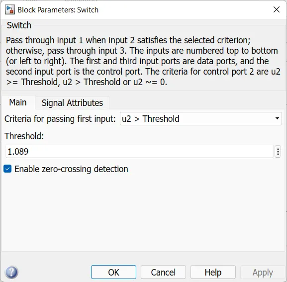
Results:
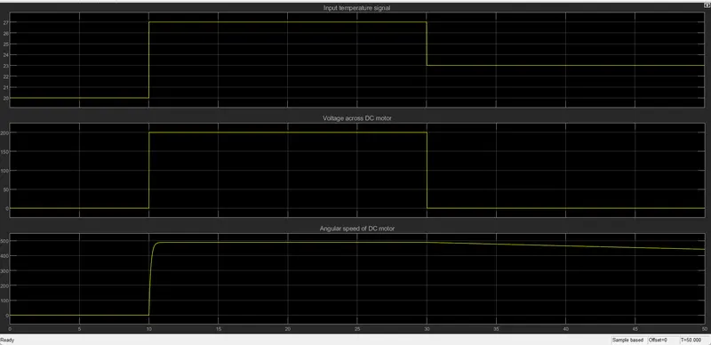
i. For the first 10 seconds, the temperature sensed by thermistor is 20°C, then the voltage across the resistor is less than the threshold value (1.089) of switch, that results in apply of no/zero voltage to fan's motor.
ii. During 10th to 30th second, the temperature sensed by thermistor is 27°C (more than 25°C), then the voltage across the resistor is greater than the threshold value of switch, that results in apply of 200V across fan's motor through controlled voltage source. So, the fan is in ON position and it is running at nearly 500 rad/sec during this period.
iii. From the 30th to 50 seconds, the temperature sensed by thermistor is 23°C, then the volltage across the resistor is less than the threshold value of the switch, that cuts off voltage to the fan's motor, so the motor's speed is gradually decreases and it will reaches to zero speed after some time due to presence of its inertia.
Note: The simulink file of the above problem is attached below.