Week - 4
1). Aim : To implement the control logic for a washing machine using State flow as per pre-defined sequence of different operating states.
Simulink model :
Various blocks are used to build the required model as shown in the below figure.
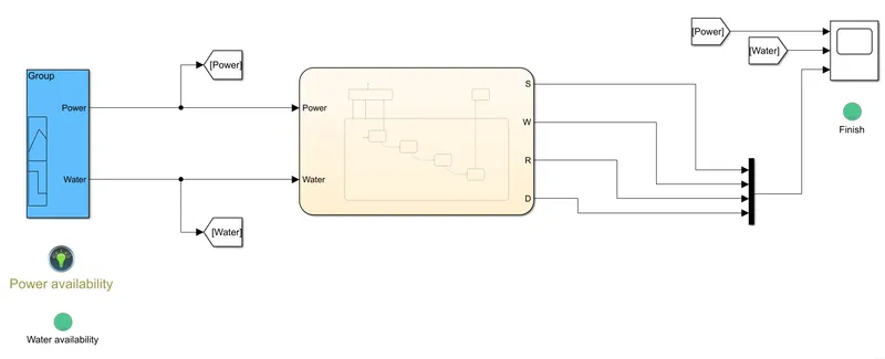
Control logic inside the chart:
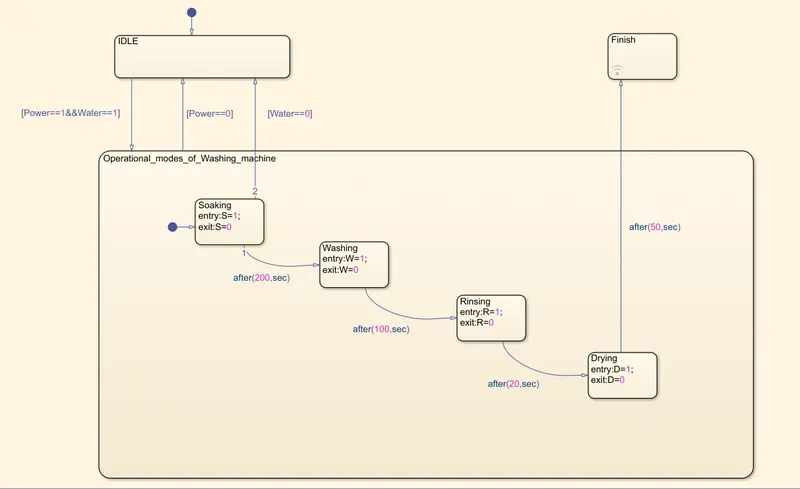
Note: Only one state is activated at a point of time in state flow while its decomposition is in Exclusive (OR) state (which is found in Modelling option in tool bar).
Here, the washing machine remains in idle state until both power and water are available.
The four modes of washing machine which are given taken as four states in which the default state (or state entering first) is Soaking, this state is activated when both the power and water are available while the idle state is deactivated.
After 200 seconds, washing state is activated while the soaking state is deactivated and this mode is proceeded for 120seconds followed by rinsing state for 20 seconds and drying state for 50 seconds.
After completion of drying state, the Finish state is activated which lights up the LED named Finish in the model.
Building Input signals:
The inputs power and water arer given through signal builder block and those signals are builded in the following way (assumed by me) that power is available from 10th second whereas the water supply is available from 30th second.
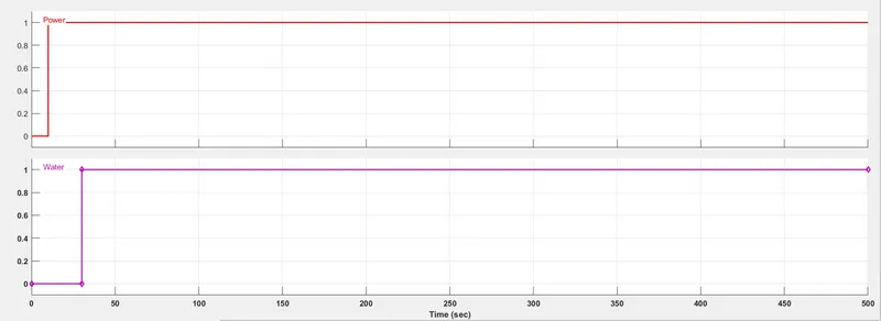
In these two signals, there are two states i,e high( amplitude=1) and low (amplitude=0) in which high state resembles power/water is available and viceversa. The status of power and water is also through two lamps named Power availability and Water availability respectively.
Results :
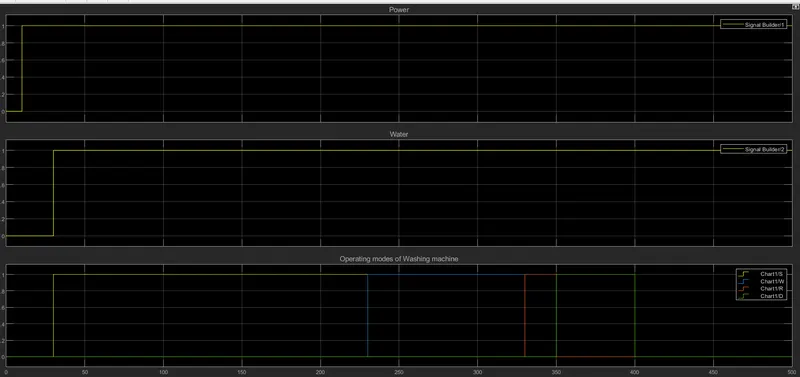
From the above results image, we can observe that the soaking state activated(S=1) from the 30th second at which both power and water supply is available. During this state, the water gets fillled into the drum of washing machine.
This soaking period is ended at 230th second after being active for 200 sec, the state is transisted to Washing (W=1) which stayed active for 100 seconds (from 230th to 330th second). During this state, the clothes gets washed using water and detergent.
Later, Rinsing state is activated (R=1) that stayed active for 20 seconds (from 330th to 350th second). During this state, the water is drained through outlet.
Finally, after rinsing state is deactivated, drying state is activated (D=1) and this state is carried out for 50 seconds (from 350th to 400th second).
2. Aim: To build a simulink chart for a automatic gear shifting against change in speed as per given data.
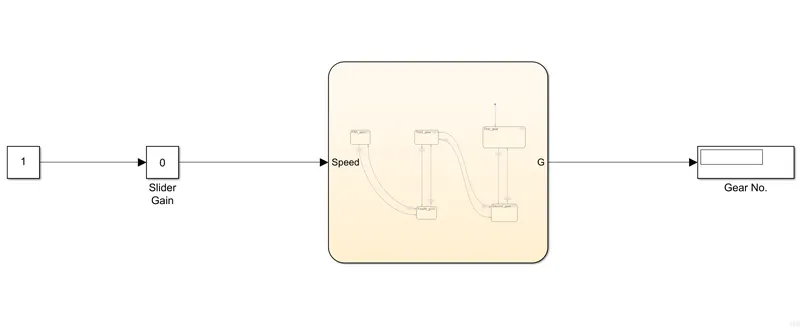
Simuliink model :
Various blocks are connected to create the required model as shown in below image.
Control logic in flow chart :
The data given for 'speed range vs gear no. is
Speed(kmph) Gear no.
0-15 1
16-25 2
26-40 3
41-60 4
Above 60 5
The below figure shows the connections of states to meet given conditions. As the no. of gears are 5, so five no. of states are created and the state transition data is defined such that the transition from one state to other state takes place whenever the speed goes out of the speed range defined for gear no.
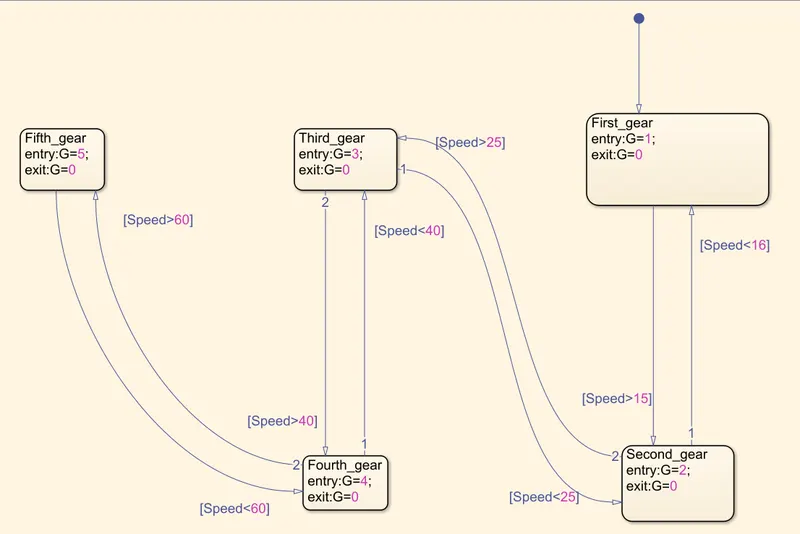
Here, the data given inside the states define that whenver a gear is activated, then the value of G is equal to number of the gear that is activated.
Results:
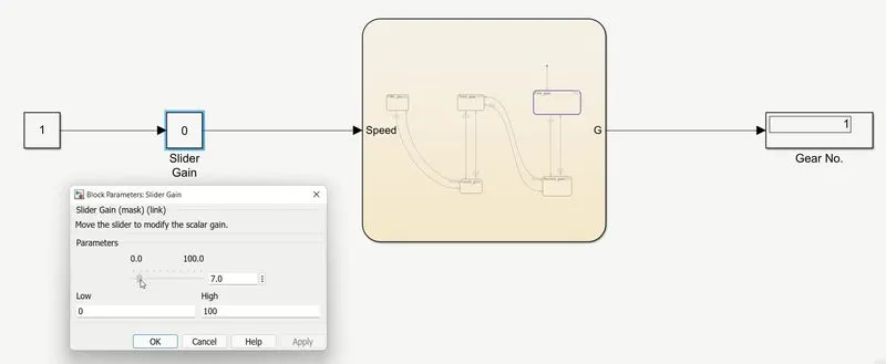
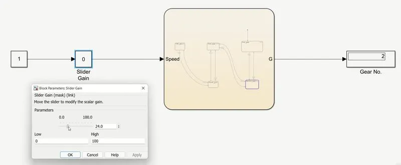
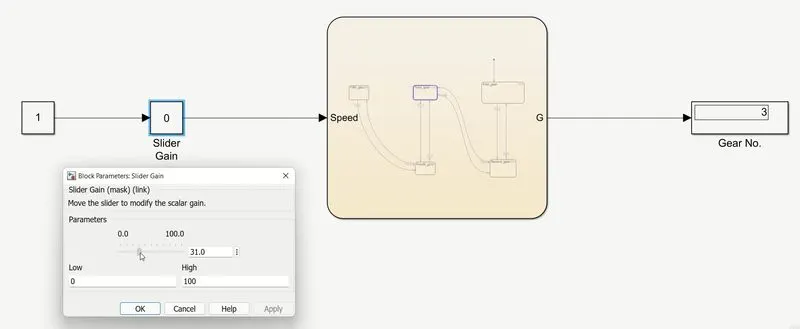
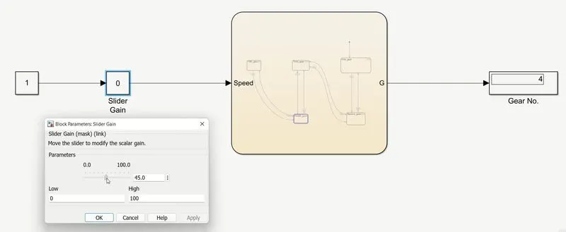
Here, inpurt speed is given through gain slider durting simullation. The states actions are defined for each state, so that the required gear state is activated whenever the input speed is in it's corresponding speed range as shown in below images.
i. Here, the input speed from slider gain is at 7kmph which is between 0 to 15kmph, so first gear state is activated and its number one is displayed in the display block.
ii. Here, the input speed is at 24kmph which is between 16 to 25, so that the second gear state is activated and its number two is displayed.
iii.Here, the input speed is 31kmph which is between 26 to 40, so third gear state is activated and its number three is displayed.
iv. Here, the input speed is 45kmph which is between 41 to 60, so fourth gear state is activated and its number four is displayed.
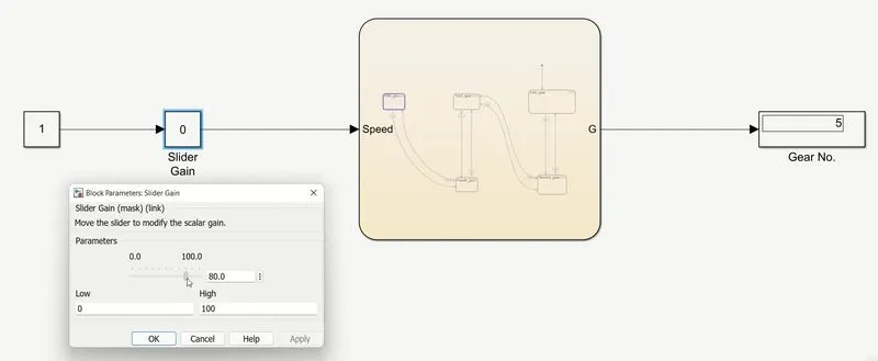
v. Here, the input speed is 80kmph which is above 60, so fifth gear state is activated and its number five is displayed.