Week 7 State of charge estimation
Objective -
For the model - Battery Systems
- To simulate the three test cases from harness dashboard and compare the results.
- What is coulomb counting?
- To explain how BMS implements coulomb counting for SOC estimation in above model.
Model of Harness Dashboard -
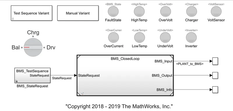
Blocks Used -
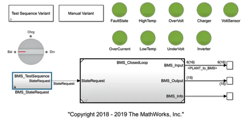
- Rotary Switch - The Rotary Switch changes the value of the connected block parameter to several specified values during simulation.
- State Request - It provides the required state needed for the simulation.
- Lamps - The Lamp block displays a color that indicates the value of the connected signal.
Subsystems - BMS_ClosedLoop
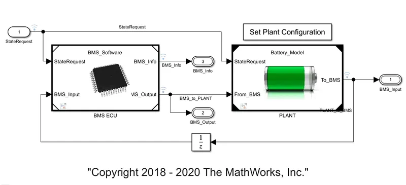
- Subsystem - BMS ECU
- In this subsystem, the control of the battery is done.
- Here, Current Power Limits is calculated.
- SOC estimation is done.
- State of Machine is determined.
- Also the balancing techniques is controlled from this subsystem.
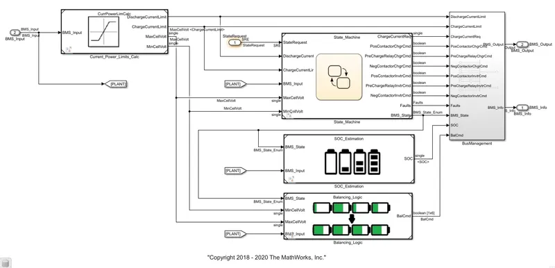
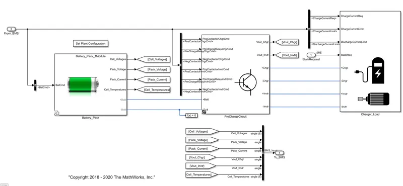
- Subsystem - PLANT
- In this subsystem, Battery module is present.
- The charging of the battery is controlled using pre charging circuit present in this subsystem.
- The charging or discharging of the battery is controlled from Charge _Load subsystem.
Test Case - 1)
- Select test case 1 in Test Sequence Variant.
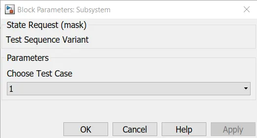
- And Run the simulation.
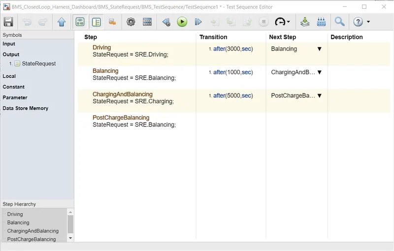
- The test sequence editor shown the below states
- Driving for 3000 seconds
- Balancing for 1000 seconds
- Charging and Balancing for 5000 seconds
- After the simulation all lamps are lit up in green color which shows no faults occur during simulation.
- The simulation results are
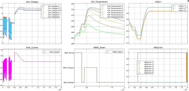
- From these graph, we can conclude that
- During driving state the battery voltage and current fluctuating according to requirement.
- The SOC decreases in this state and cell tempreature increases.
- In the Charging state, Cell voltage and current increases rapidly.
- Also the cell tempreature increases at a faster rate.
- During Standby state, the voltage level is almost constant after balancing is done.
- The cell current becomes constant after decrease to some extent.
- As the battery is in idle condition the temperature also decreases.
Test Case - 2)
- Select test case 2 in Test Sequence Variant.
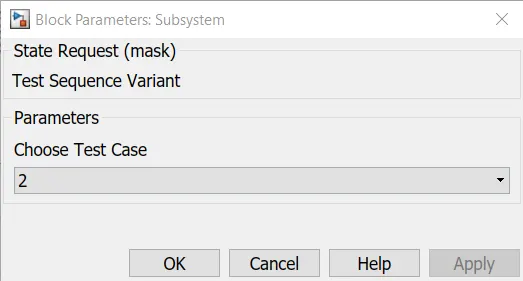
- And Run the simulation.
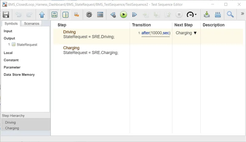
- The test sequence editor shown the below states
- Driving for 10000 seconds.
- After the simulation all lamps are lit up in green color which shows no faults occur during simulation.
- The simulation results are
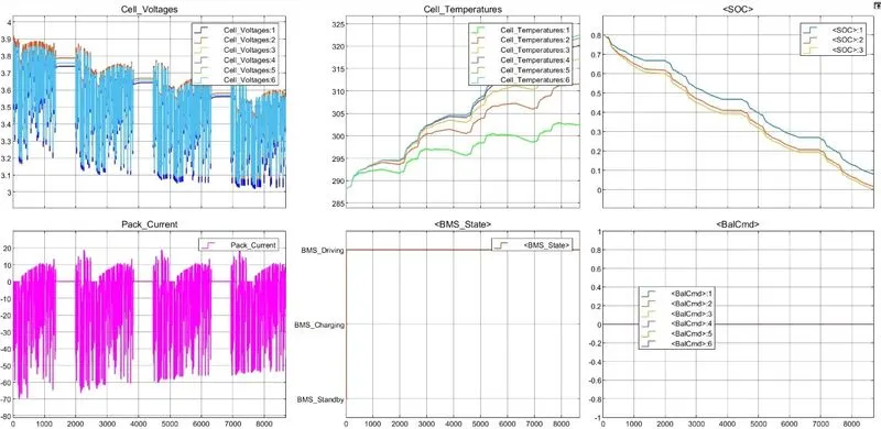
- From these graph, we can conclude that
- During driving state the battery voltage fluctuating according to requirement.
- The cell current also fluctuates according to the voltage level.
- The cell tempreature keeps on increasing as the battery is used in driving state only.
- The SOC level decreases in almost linearly.
- The cell balancing is not happen in this state.
Test Case - 3)
- Select test case 3 in Test Sequence Variant.
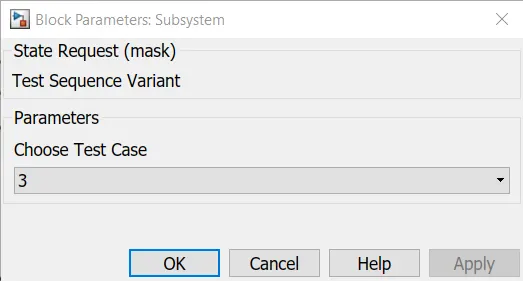
- And Run the simulation.
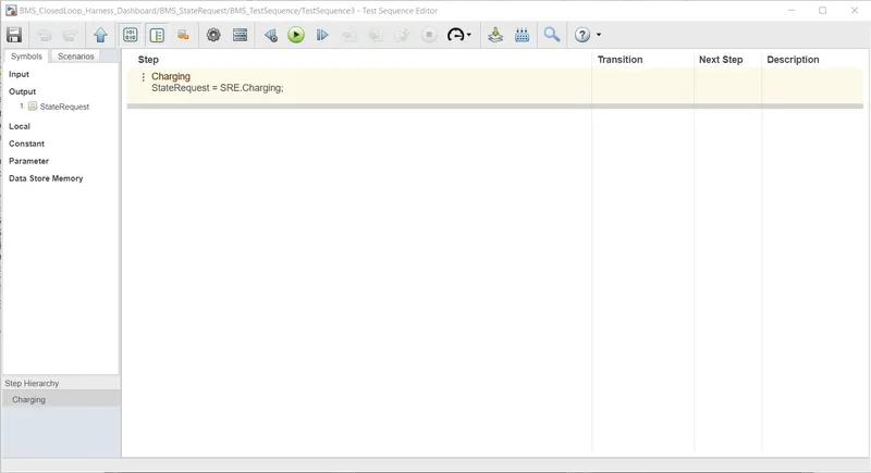
- The test sequence editor shown the below states
- the only state in this test is Charging state.
- After the simulation all lamps are lit up in green color which shows no faults occur during simulation.
- The simulation results are
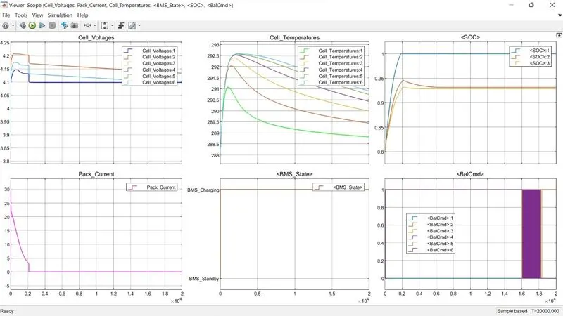
- From these graph, we can conclude that
- As only charging of battery is done in this case.
- When the cell voltage level reaches maximum cell voltage i.e. 4.2 V cell balancing is done.
- After cell balancing the cell voltages becomes 4.1 V.
- The cell current decreases during charging and becomes zero after cell balancing procees.
- The cell temperature increases when the cell voltage level is increasing.
- As the balancing starts cell temperature starts decreasing.
Coulomb Counting -
- The Coulomb counting method measures the discharging current of a battery and integrates the discharging current over time in order to estimate SOC.
- Coulomb counting method is done to estimate the SOC(t).
- It is estimated from the discharging current I(t) and previously estimated SOC values SOC(t-1).
- SOC is calculated by the following equation
`SOC(t) = SOC(t-1) + (intI(t)dt)/(Total Capacity)`
- There are several factors that affect the accuracy of Coulomb counting method such as
- temperature
- battery history
- discharge current
- cycle life
Modified Coulomb Counting -
- To improve the Coulomb counting method, a new technique called modified Coulomb counting method is proposed.
- The modified Coulomb counting method uses the corrected current to improve the accuracy of estimation.
- The corrected current is the function of discharging current.
- There is a quadratic relationship between the corrected current and discharging current of battery.
- By practice of experimental data, corrected current is calculated by the following form
`I_c(t) = k_2I(t)^2 + k_1I(t) + k_0`
- where, `k_2, k_1 and k_0` are constant values obtained from the practice experimental data.
- In modified Coulomb counting method, SOC is calculated by the following equation
`SOC(t) = SOC(t-1) + (intI_c(t)dt)/(Total Capacity)`
- The experimental results show that the accuracy of the modified Coulomb counting method is superior to the conventional Coulomb counting method.
Implementation of Coulomb Counting for SOC Estimation -
- The SOC Estimation is done by BMS ECU.
- The SOC Estimation subsystem is shown below
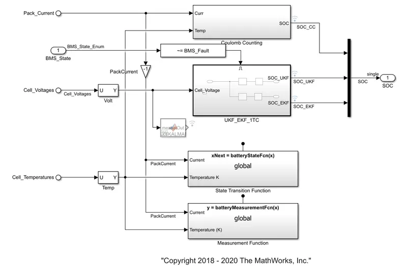
- The coulomb counting subsystem contains following blocks
- Gain - The Gain block multiplies the input by a constant value.
- 1-D Lookup Table - It evaluate a sampled representation of a function in N variables.
- Product - It multiply and divide scalars and nonscalars or multiply and invert matrices.
- Discrete Time Integrator - It perform discrete-time integration or accumulation of signal.
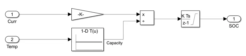
- Gain block is used to convert the current rate value from ampere per seconds to ampere per hour.
- The battery capacity values are provided from Lookup Tables.
- The ratio of Current and Capacity is integrated using time integrator.
- The output of integrator gives the SOC value.