Simulink - Project
Objective -
To analyze BAJA All Terrain Vehicle (ATV) different models with Continuous Variable Transmission (CVT) using Simulink.
Models -
- BAJA ATV model without Dashboard.
- BAJA ATV model with Dashboard.
- BAJA ATV model with CVT Ratio as RPM.
- BAJA ATV model - Data Extraction.
- BAJA ATV model with Mapped Lookup Table without Dashboard.
- BAJA ATV model with Mapped Lookup Table with Dashboard.
Theory -
All Terrain Vehicle (ATV) -
- An all-terrain vehicle (ATV), also known as a light utility vehicle (LUV), a quad bike, or simply a quad.
- As defined by the American National Standards Institute (ANSI), is a vehicle that travels on low-pressure tires, with a seat that is straddled by the operator, along with handlebars for steering control.
- As the name implies, it is designed to handle a wider variety of terrain than most other vehicles.
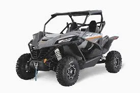
- By the current ANSI definition, ATVs are intended for use by a single operator, although some companies have developed ATVs intended for use by the operator and one passenger. These ATVs are referred to as tandem ATVs.
- The rider sits on and operates these vehicles like a motorcycle, but the extra wheels give more stability at slower speeds.
Continuous Variable Transmission (CVT) -
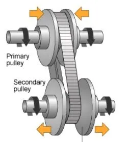
- A continuously variable transmission (CVT) is an automatic transmission that can change seamlessly through a continuous range of gear ratios.
- This contrasts with other transmissions that provide a limited number of gear ratios in fixed steps.
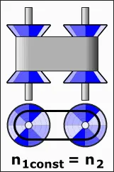
- The flexibility of a CVT with suitable control may allow the engine to operate at a constant RPM while the vehicle moves at varying speeds.
- The most common type of CVT uses two pulleys connected by a belt or chain.
- CVTs are used in automobiles, tractors, motor scooters, snowmobiles, bicycles and earthmoving equipment.
BAJA SAE -
- Baja SAE is an Collegiate Design Series competition run by the Society of Automotive Engineers International (SAE International).
- Teams of students from universities all over the world design and build small off-road cars.
- BAJA is basically an ATV competition where students get to design and develop their own ATV keeping in mind various considerations of design as well as safety.
- An ATV is designed in order to run on various terrains such as soil, Gravel, pebbles, etc. so due to difficult terrain our main focus was on driver safety and better ergonomics at the same time.
Common Block Used -
- Signal Builder - The Signal Builder block allows you to create interchangeable groups of piecewise linear signal sources and use them in a model.
- GOTO - The Goto block passes its input to its corresponding From blocks. The input can be a real- or complex-valued signal or vector of any data type. From and Goto blocks allow you to pass a signal from one block to another without actually connecting them. A Goto block can pass its input signal to more than one From block, although a From block can receive a signal from only one Goto block. The input to that Goto block is passed to the From blocks associated with it as though the blocks were physically connected.

- From - The From block accepts a signal from a corresponding Goto block, then passes it as output. The data type of the output is the same as that of the input from the Goto block. From and Goto blocks allow you to pass a signal from one block to another without actually connecting them.

- Simulink PS Converter - The Simulink-PS Converter block converts the input Simulink signal into a physical signal. Use this block to connect Simulink sources or other Simulink blocks to the inputs of a Simscape physical network.
- Solver Configuration - Each physical network represented by a connected Simscape block diagram requires solver settings information for simulation. The Solver Configuration block specifies the solver parameters that your model needs before you can begin simulation. Each topologically distinct Simscape block diagram requires exactly one Solver Configuration block to be connected to it.
- Mechanical Rotational Reference - The Mechanical Rotational Reference block represents a reference point, or frame, for all mechanical rotational ports. All rotational ports that are rigidly clamped to the frame (ground) must be connected to a Mechanical Rotational Reference block.
- Scope - The Simulink Scope block display time domain signals. It display signals generated during simulation.

- Simple Gear - The Simple Gear block represents a gearbox that constrains the connected driveline axes of the base gear, B, and the follower gear, F, to corotate with a fixed ratio that you specify.
The follower-base gear ratio is
`g_(FB) = r_F/r_B = N_F/N_B`
where:
`N_B` is the number of teeth in the base gear.
`N_F` is the number of teeth in the follower gear.
- Generic Engine - The Generic Engine block represents a general internal combustion engine. This block is a suitable generic engine for spark-ignition and diesel. Speed-power and speed-torque parameterizations are provided. A throttle physical signal input specifies the normalized engine torque.
Common Subsystems Created are -
- Engine Sensor - It is a subsystem created using following blocks -
- Ideal Rotational Motion Sensor –
The Ideal Rotational Motion Sensor block represents an ideal mechanical rotational motion sensor, that is, a device that converts an across variable measured between two mechanical rotational nodes into a control signal proportional to angular velocity or angle. - Mechanical rotational Reference –
The Mechanical Rotational Reference block represents a reference point, or frame, for all mechanical rotational ports. - PS-Simulink Converter –
Converts the input Physical Signal to a Simulink output signal. - Scope –
Display signals generated during simulation. - PS terminator –
Use the PS Terminator block to cap physical signal output ports that do not connect to other blocks.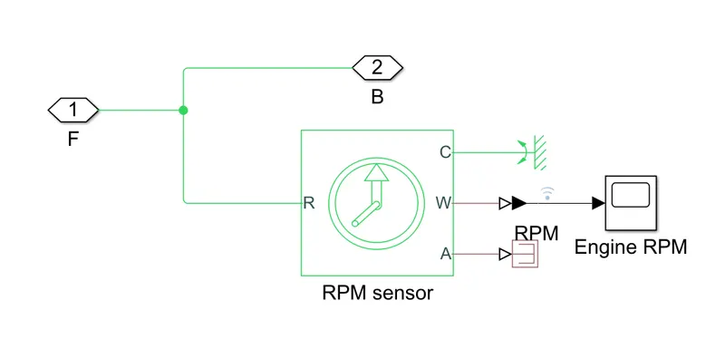
The Engine Sensor Subsystem is shown in above figure.
- Ideal Rotational Motion Sensor –
- CVT - This subsystem is created using following blocks -
- Inertia –
The block represents an ideal mechanical rotational inertia. - Ideal Rotational Motion Sensor –
The Ideal Rotational Motion Sensor block represents an ideal mechanical rotational motion sensor, that is, a device that converts an across variable measured between two mechanical rotational nodes into a control signal proportional to angular velocity or angle. - Mechanical rotational Reference – The Mechanical Rotational Reference block represents a reference point, or frame, for all mechanical rotational ports.
- PS-Simulink Converter – Converts the input Physical Signal to a Simulink output signal.
- Goto – The Goto block passes its input to its corresponding From blocks. The input can be a real or complex-valued signal or vector of any data type. From and Goto blocks allow you to pass a signal from one block to another without actually connecting them.
- PS terminator – Use the PS Terminator block to cap physical signal output ports that do not connect to other blocks.
- Variable Ratio Transmission –
The Variable Ratio Transmission block represents a gearbox that dynamically transfers motion and torque between the two connected driveshaft axes, the base and the follower. It is a variable ratio gearbox such as implemented by mechanical belt CVT, electric, or hydraulic transmissions.
The CVT subsystem is shown below -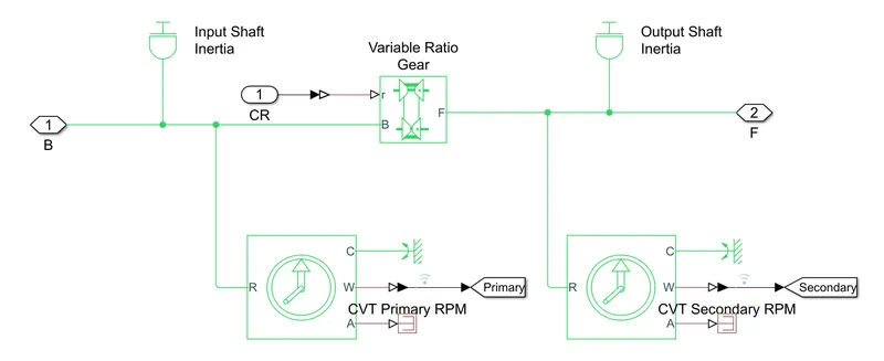
- Inertia –
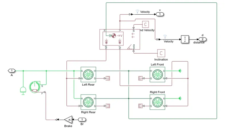
- Vehicle Body - This subsystem is created using blocks as given below -
- Inertia – The block represents an ideal mechanical rotational inertia.
- Double Shoe Brake –
The Double-Shoe Brake block represents a frictional brake with two pivoted rigid shoes that press against a rotating drum to produce a braking action. - Gain –

The Gain block multiplies the input by a constant value (gain). The input and the gain can each be a scalar, vector, or matrix. - Tire –
The Tire (Magic Formula) block models a tire with longitudinal behavior given by the Magic Formula, an empirical equation based on four fitting coefficients. The block can model tire dynamics under constant or variable pavement conditions.Represents the longitudinal behavior of a highway tire characterized by the tire Magic Formula. - PS terminator – Use this block to terminate physical signal outputs.
- Vehicle Body –
The Vehicle Body block represents a two-axle vehicle body in longitudinal motion. The vehicle can have the same or a different number of wheels on each axle. - PS Constant –
The PS Constant block generates a physical signal of a constant value. - PS-Simulink Converter – Converts the input Physical Signal to a Simulink output signal.
- Integrator –

The Integrator block outputs the value of the integral of its input signal with respect to the time.
The vehicle body subsystem block is shown below -
BAJA ATV Models -
BAJA ATV Model without Dashboard -
- Model -
The filename for this model is "cvtModel.slx".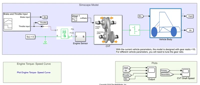
- Working -
- The Signal Bulider block is used for providing Brake input, Throttle input and CVT Gear Ratio input.
- The torque vector and speed vector input is provided from MATLAB Workspace.
- The Throttle input is given to the Engine where the engine parameters changes accordingly.
- The output from the Generic Engine is the pass through the Engine Sensor block.
- This sensor block records the rpm of engineand forwards the ouput from engine.
- The break input is given to the Double Shoe Brake block via Gain block.
- The ouput from brake block provided to tires.
- The vehicle body block provides velocity for all tires.
- It also provides ouput signal velocity and displacement using integrator.
- Input Data -
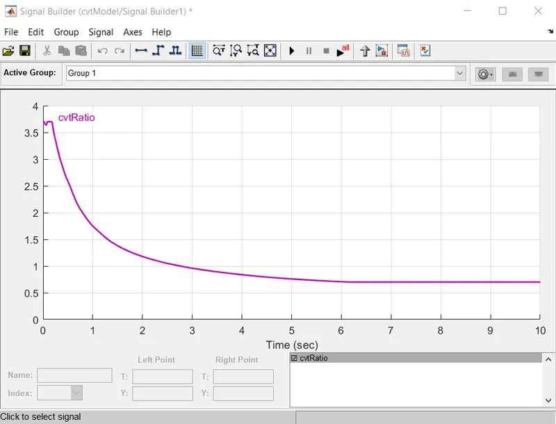
- Signal Builder Block Input -
- Brake and Throttle Input -
- CVT Ratio -
- Brake and Throttle Input -
- MATLAB Workspace -
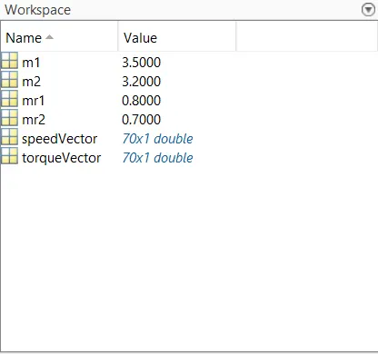
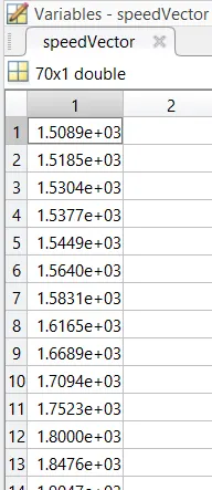
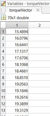
- Gear Ratio is 10.
- Signal Builder Block Input -
- Results -
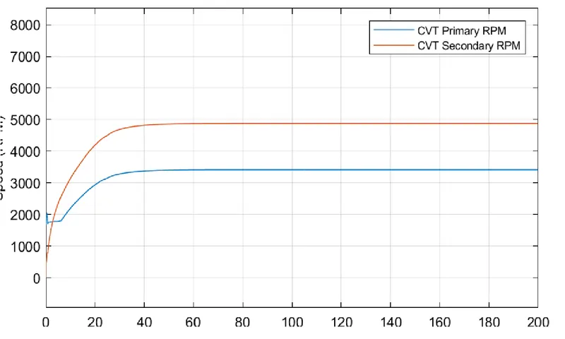
The simulation time is 200 seconds.- Engine RPM -
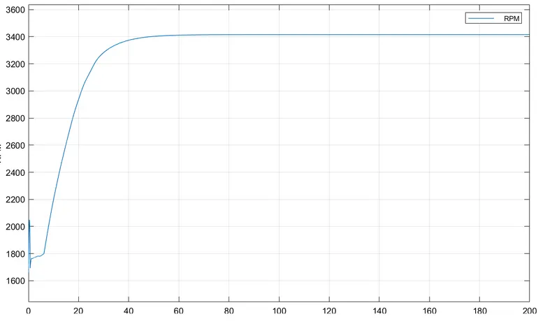
- CVT Shaft Speed -
- Velocity and Displacement -
- Engine RPM -
BAJA ATV model with Dashboard -
- Model -
The filename for this model is "cvtModel_dashboard.slx".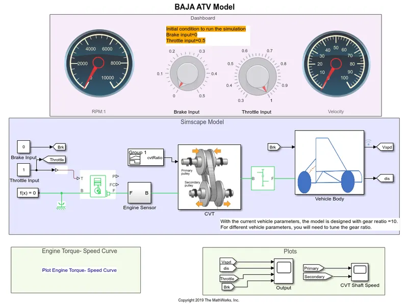
- Blocks used -
- Circular Gauge -
The Circular Gauge block displays the value of the connected signal on a circular gauge that you can design to look like a gauge in a real system. - Knob -
The Knob block tunes the value of the connected block parameter to during simulation.
The others blocks used are given in common used block.
- Circular Gauge -
- Working -
- The working is same as working of BAJA ATV Model without Dashboard.
- The only difference is here we can modify input i.e. throttle input and brake input during simulation using Knob.
- Input Data -
- CVT Gear Ratio -
The CVT Gear Ratio is provided using Signal Builder Block. - MATLAB Workspace -
- Gear Ratio is 10.
- CVT Gear Ratio -
- Results -
- Case -1 : Brake = 0 and Throttle = 0.5
- Engine RPM -
- CVT Shaft Speed -
- Velocity and Displacement -
- Engine RPM -
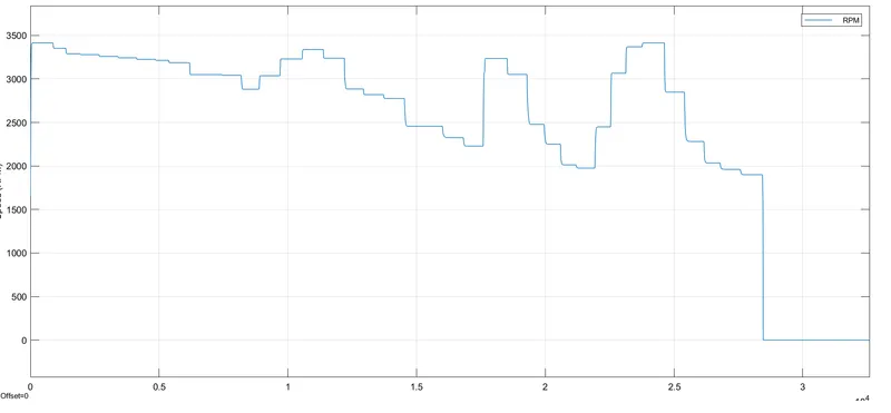
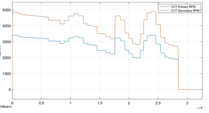
- Case -2 : Brake = Varying and Throttle = 0.5
The simulation time is set to infinity for this case.
As the throttle value is constant, brake value is varying. When the brake value exceeds 0.2, the rpm becomes 0. So the brake applied lies between 0 to 0.2.
- Engine RPM -
- CVT Shaft Speed -
- Velocity and Displacement -
- Engine RPM -
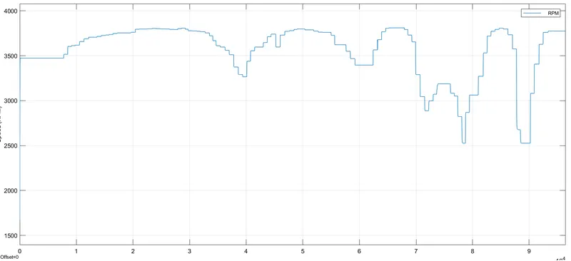
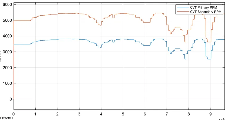
- Case -3 : Brake = 0 and Throttle = Varying
The simulation time for this case is infinity.- Engine RPM -
- CVT Shaft Speed -
- Velocity and Displacement -
- Engine RPM -
- Case -1 : Brake = 0 and Throttle = 0.5
BAJA ATV Model with CVT Ratio as RPM -
- Model -
The filename for this model is "cvtModel_cvtratio_rpm.slx".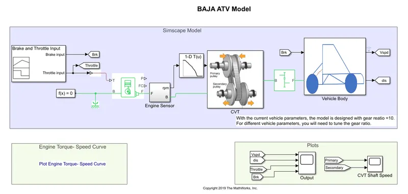
- Block Used -
- Lookup Table (n-D) -
This block maps inputs to an output value by looking up or interpolating a table of values you define with block parameters.
- Lookup Table (n-D) -
- Working -
- The working is same as of working of BAJA ATV Model without Dashboard.
- The difference here is that instead of signal builder input for CVT Gear Ratio here engine rpm is given as CVT Ratio by using Lookup Table block.
- Input Data -
- Brake and Throttle Input -
- Lookup Table Input -
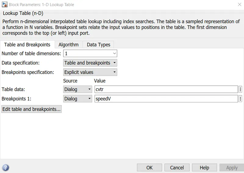
- CVT Ratio is given the engine RPM output provided by Generic Engine.
- Gear Ratio is 10.
- Brake and Throttle Input -
- Results -
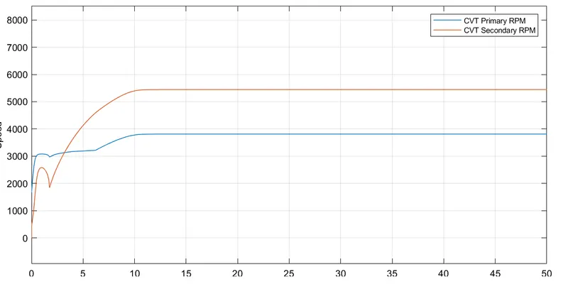
The simulation time is 50 seconds.
- Engine RPM -
Here this output is also input for CVT Gear Ratio for CVT subsystem.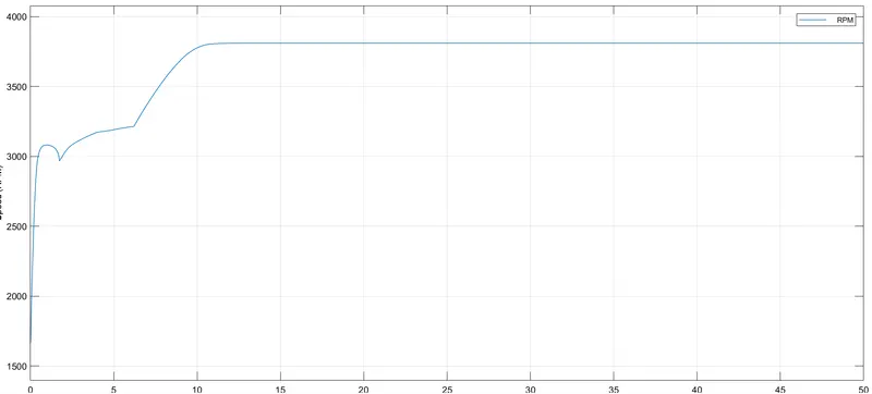
- CVT Shaft Speed -
- Output Plots -
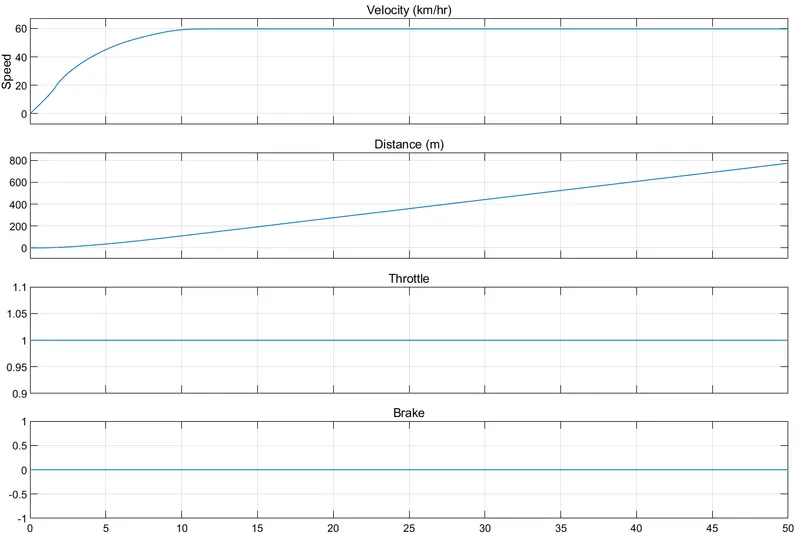
- Engine RPM -
BAJA ATV model with Data Extraction -
- Model -
The filename for this model is "cvtModel_data.slx".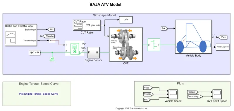
- Working -
- The working is same as working of BAJA ATV Model without Dashboard.
- The only difference is here the output gets saved to MATLAB workspace files using To Workspace Block.
- Input Data -
- Signal Builder -
- Brake and Throttle Input -
- CVT Ratio -
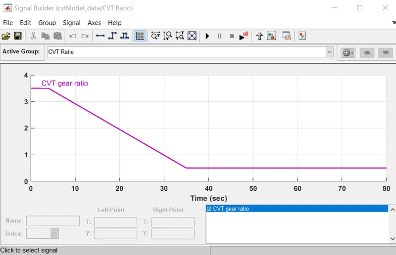
- Brake and Throttle Input -
- Workspace -
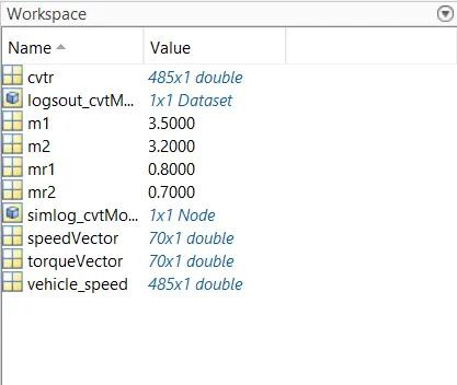
- Gear Ratio is 12.
- Signal Builder -
- Results -
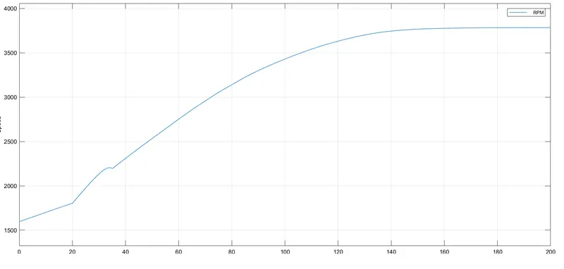
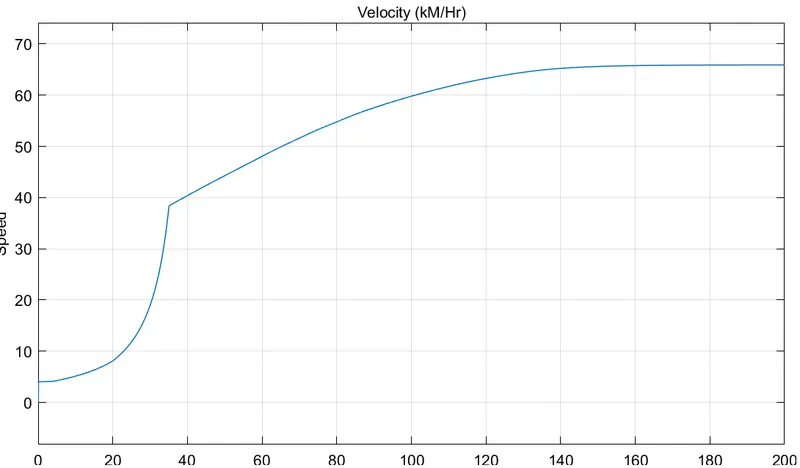
The simulation time for this model is 200 seconds.- Engine RPM -
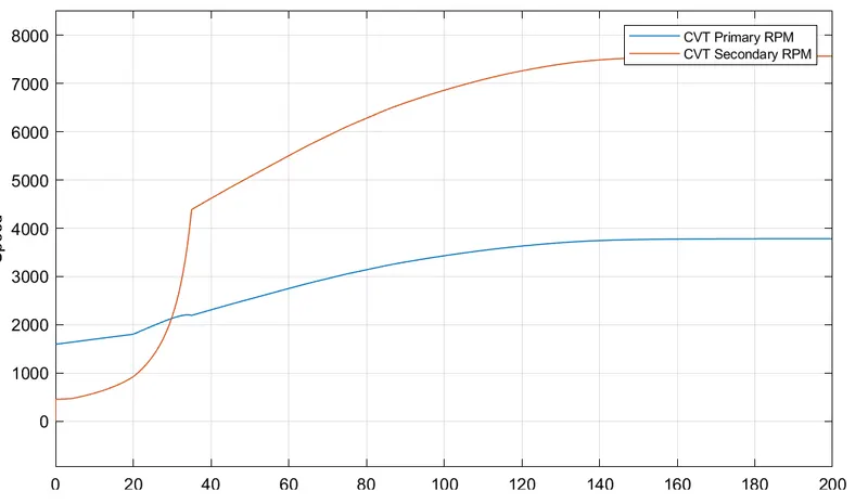
- CVT Shaft Speed -
- Vehicle Speed -
- Engine RPM -
BAJA ATV model with Mapped Lookup Table without Dashboard -
- Model -
The filename for this model is "cvtModel_mapped.slx".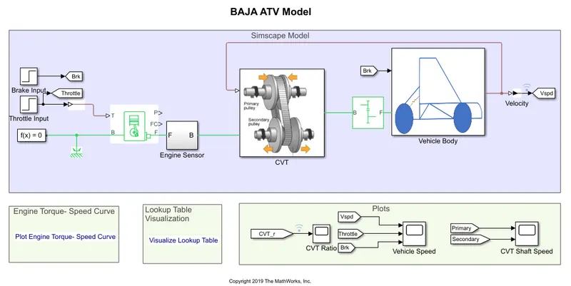
- Blocks used -
- Step -

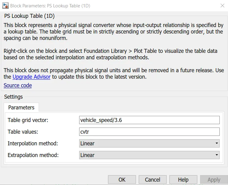
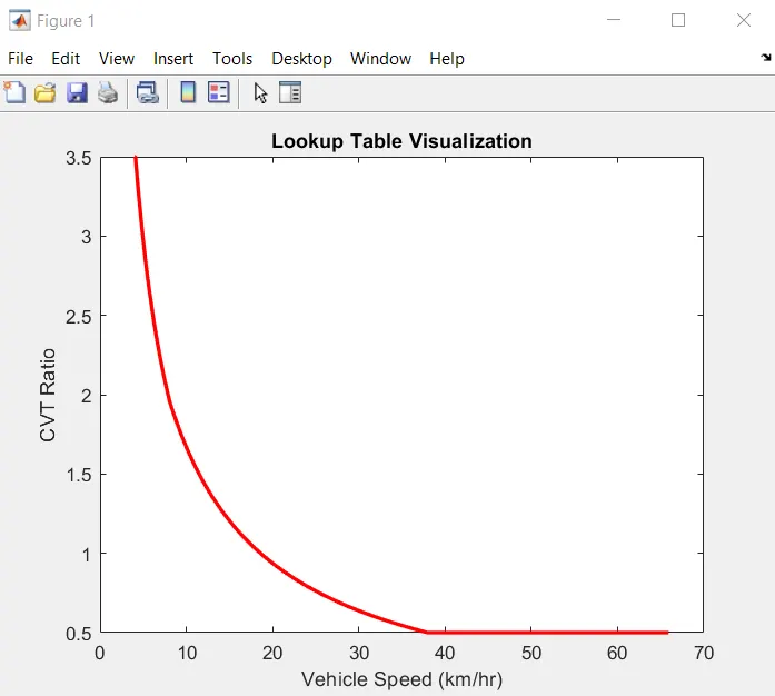
The Step block provides a step between two definable levels at a specified time. - PS Lookup Table -
The PS Lookup Table (1D) block computes an approximation to some function f=f(x) given data vectors x and f. Both the input and the output are physical signals.
- Step -
- Working -
- The working is same as working of BAJA ATV Model without Dashboard.
- The difference is step input signal is used here.
- Also in CVT Subsystem, we are using the output signal from the vehicle body as the input to the CVT as the CVT gear ratio. It needs to be loaded in the workspace using the file name Lookuptable_data.mat.
- Input Data -
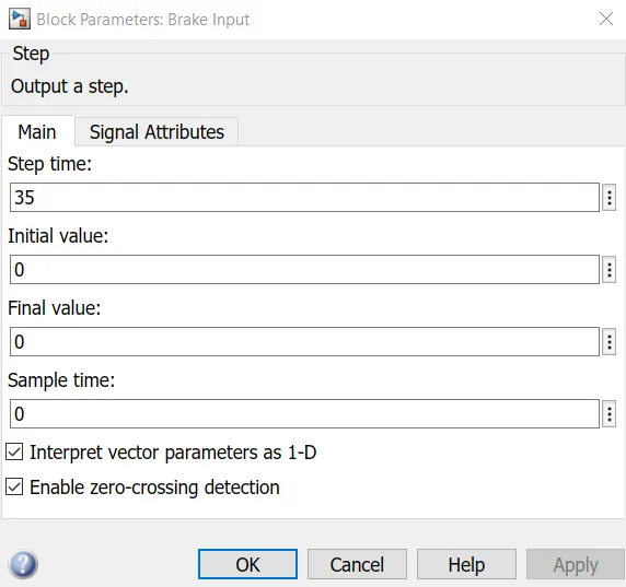
- Brake Input -
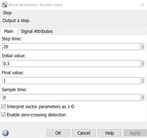
- Throttle Input -
- Lookup Table -
- Gear Ratio is 12.
- Brake Input -
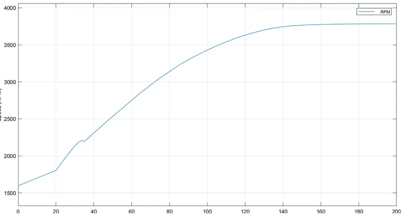
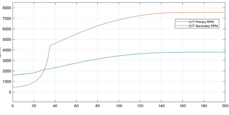
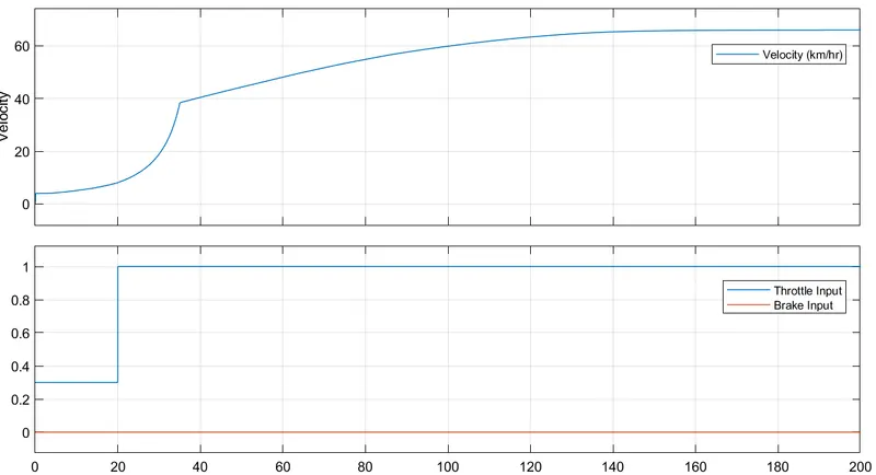
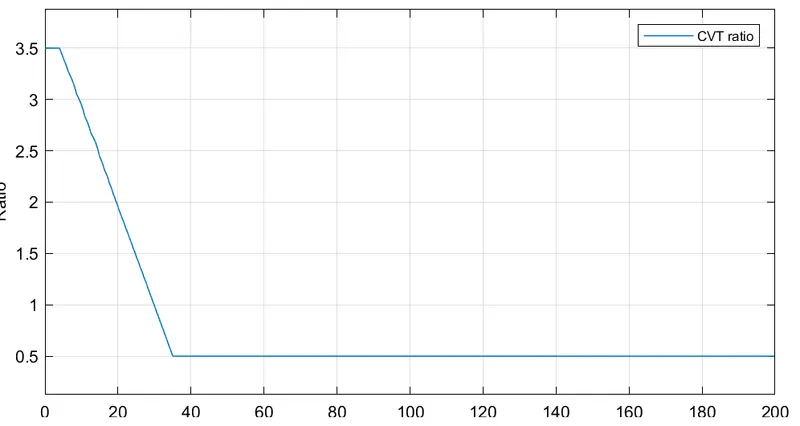
- Results -
- Engine RPM -
- CVT Shaft Speed -
- Vehicle Speed -
- CVT Ratio -
- Engine RPM -
BAJA ATV model with Mapped Lookup Table with Dashboard -
- Model -
The filename for this model is "cvtModel_dashboard_mapped.slx".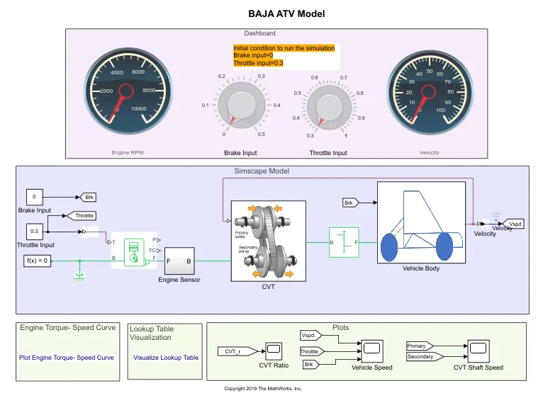
- Working -
- The working is same as of working of BAJA ATV model with Mapped Lookup Table without Dashboard.
- The difference here is that the input is provided by using knob.
- Gear Ratio is 12.
- Results -
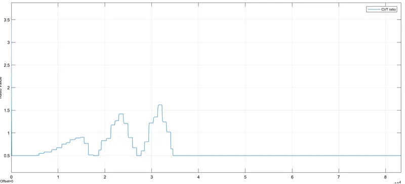
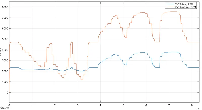
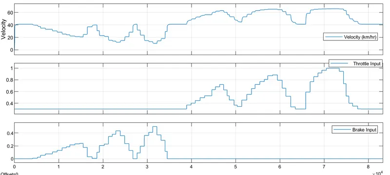
The simulation time for this model is infinity.- Engine RPM -
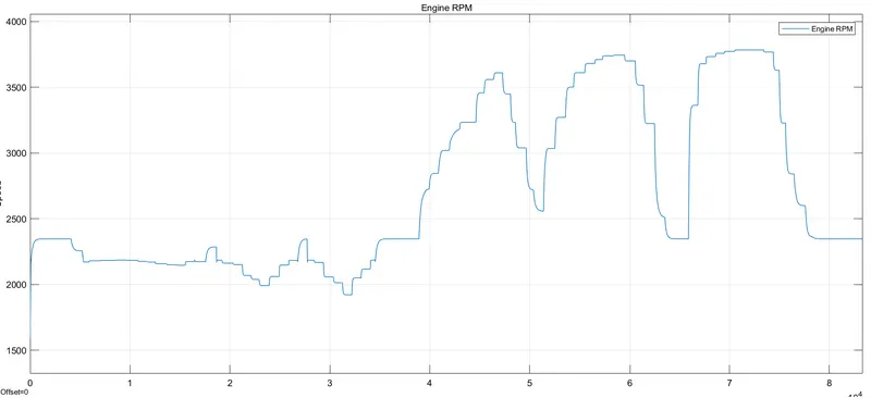
- CVT Ratio -
- CVT Shaft Speed -
- Vehicle Speed -
- Engine RPM -
Observations -
- When the throttle is being increased, the CVT Ratio reaches the state where engine speed is maximum.
- When the throttle is being decreased the CVT ratio will move towards where the minimum engine speed state.
- While the braking is applied, the CVT Ratio increases so that it can achieve the nearest state of Minimum Engine Speed.
- When the braking is removed, the CVT Ratio decreases so that it achieve the state of Maximum Engine Speed.
References -
- Model Link - https://www.mathworks.com/matlabcentral/fileexchange/70576-baja-all-terrain-vehicle-atv-model
- MATLAB HELP.