Simulink - Week 2
Objective -
To make a Simulink model of Doorbell using solenoid block with the following details:
- In the above arrangement, when the switch is closed the electromagnet receives electrical power from the battery and pulls the metal arm to hit the bell producing sound.
- Create a situation where the switch is closed for 2 seconds and then released. Observe the physical movement of the plunger.
Assumptions -
- Simulation Time is 12 seconds.
- Input Signal Pulse amplitude is 1 with pulse width of 50% of period, phase delay of 2 seconds and period is 6 seconds.
Model -
Explanation -
Solenoid -
A solenoid is a device comprised of a coil of wire, the housing and a moveable plunger (armature). When an electrical current is introduced, a magnetic field forms around the coil which draws the plunger in. More simply, a solenoid converts electrical energy into mechanical work.
Working of Solenoid in a Doorbell -
When pressing the switch, it closes an electrical circuit so that current flows through the electromagnet (or electromagnets) by way of a transformer. This current is then passed through the electromagnet wire. The magnetic field of the electromagnet is put to work to drive some sort of a noisemaking apparatus,here the contact arm is attached to a long clapper that hits a metal bell.
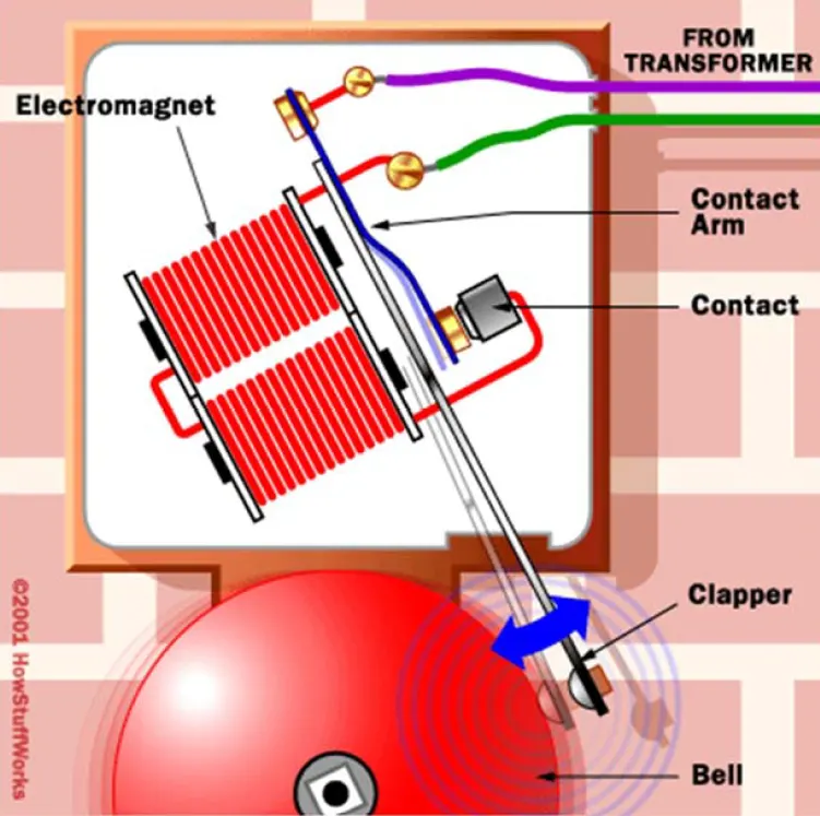
When the circuit is closed, the electromagnet is magnetized so it pulls up on the contact arm. This breaks the doorbell circuit, which shuts off the electromagnet. The arm falls down, closing the circuit again and the process repeats. One end of the electromagnet wire is connected directly to one end of the electrical circuit. The other end of the wire connects to a metal contact, which is adjacent to a moving contact arm.
The contact arm is a thin piece of light, conductive metal, with a thin iron bar soldered onto it. The anchored end of the contact arm is wired to the electrical circuit. When the electromagnet is turned off, the free end of the arm rests against the contact point. This forms a connection between that end of the wire and the electrical circuit. In other words, electricity can flow through the electromagnet when the circuit is closed. Closing the doorbell circuit (by pressing the switch) puts this mechanism in motion. Initially, the electromagnetic field attracts the iron bar, which pulls the contact arm off the stationary metal contact. This breaks the connection between the circuit and electromagnet, so the electromagnet shuts off.
Without a magnetic field pulling it back, the contact arm snaps back into position against the stationary contact. This reestablishes the connection between the electromagnet and the circuit, and the current can flow through it again. The magnetic field draws the contact arm up, and the process repeats itself as long as you hold down the switch. In this way, the electromagnet keeps shutting itself on and off.
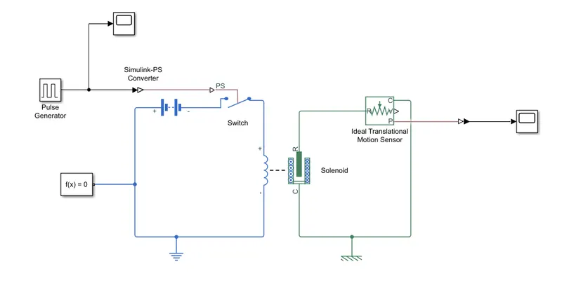
The simulink model is explained as -
- The switch used here is controlled by external physical signal i.e. input signal.
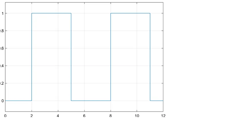
- The input signal is provided by using Pulse Generator block.
- A scope is used to check the input signal.
- A Simulink to PS Converter is required to connect pulse generator to switch as pulse generator provides simulink signal whereas switch requires physical signal.
- A Battery and Electrical Reference are provided to give power and a reference to the switch.
- A Solenoid is connected between switch and electrical reference.
- The port 'C' of solenoid and is connected with mechanical reference with
- The Ideal Translational Motion Sensor is provided for the plunger movement observations.
- The port 'C' of motion sensor is connected to the mechanical reference and port 'R' is connected to the port 'R' of the solenoid.
- For the observation of position of plunger, a scope is provided at port 'P' of motion sensor via PS to Simulink Converter.
- For the smooth compilation, a solver configuration is connected to the system.
Observations -
The observations from this study are -
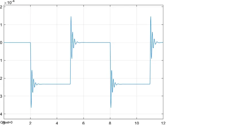
- When the input signal is provided at 2 seconds, the plunger displaces with some oscillations followed by damping.
- When the input signal is cut-off at 5 seconds, the plunger moves back to its original position with oscillation followed by damping.
- This process repeats for the next cycle.
--------------------------------------------------------------------------------------------------------------------------------------------------------------
Objective -
To use a thermistor to sense the temperature of a heater & turn on or turn off the fan as per the below conditions -
- Temperature source: 20 °C ( 293K ) from 0 to 10 seconds, 27 °C ( 300K ) from 10 to 30 seconds, 23 °C ( 296 K ) from 30 to 50 seconds.
- Fan conditions: ON if the temperature above 25 °C, OFF otherwise.
Assumptions -
- Simulation Time is 50 seconds.
- Temperature calculation are done in Kelvin ( 'K' ) unit.
Model -
Explanation -
Thermistor -
A thermistor is a resistance thermometer, or a resistor whose resistance is dependent on temperature.
Signal Builder -
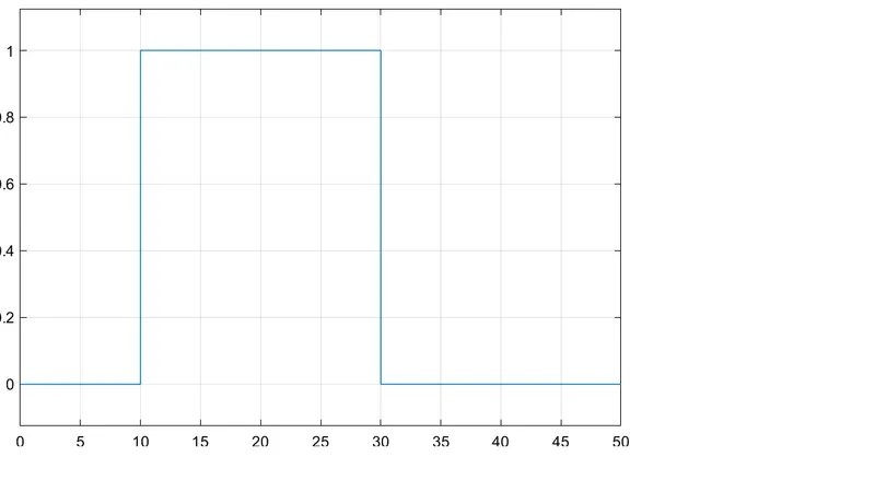
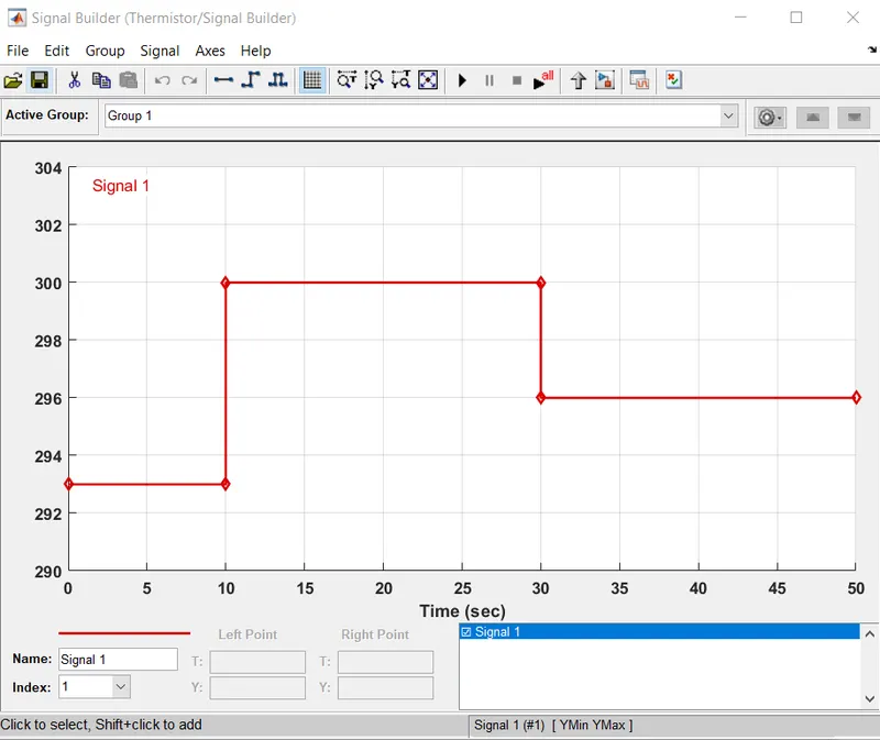
The Signal Builder block allows you to create interchangeable groups of piecewise linear signal sources and use them in a model. For the given temperature condition, signal builder is used for creating the input signal as given below -
- From time 0 to 10 seconds, temperature is 20 °C ( 293K ).
- From time 10 to 30 seconds, temperature is 27 °C ( 300K ).
- From time 30 to 50 seconds, temperature is 23 °C ( 296 K ).
Controlled Temperature Source -
The Controlled Temperature Source block represents an ideal source of thermal energy that is powerful enough to maintain specified temperature difference across the source regardless of the heat flow consumed by the system.
As the temperature source requires a physical signal, a Simulink to PS Converter is connected with derivative enabled in Input Handling menu due to derivative present in thermistor equation.
Voltage Sensor -
The Voltage Sensor device that converts voltage measured between two points of an electrical circuit into a physical signal proportional to the voltage. Connections '+' and '–' are electrical conserving ports through which the sensor is connected to the circuit. Connection V is a physical signal port that outputs the measurement result.
Solver Configuration -
The Solver Configuration block specifies the solver parameters that your model needs before you can begin simulation.
The working of model is given as -
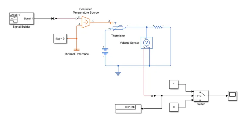
- The input signal from signal builder is provided to temperature source.
- Thermistor Resistance will vary acoording to this temperature.
- Hence, voltage drop across voltage sensor will change.
- Voltage sensor will compare it to reference value and provide a physical output signal to port 'V'.
- This output signal can be study via display block after converting it using PS to Simulink Converter.
- To get the graphical representation of this result connect a scope to display via switch with threshold value of what we get it after running the simulation i.e. 0.01099.
Observations -
The observation of when fan will switch ON or OFF is given by below plot -
- When the temperature is above 298K ( or 25°C ), the fan turns on i.e. for time 10 seconds to 30 seconds tempreature is 300K ( or 27°C).
- When tempreature is below 298K ( or 25°C ), the fan turns off i.e. for time 0 seconds to 10 seconds temperature is 293K ( or 20°C ) and for time 30 seconds to 50 seconds temperature is 296K ( or 23°C ).