Week-6 Challenge: EV Drivetrain
Objective -
To discuss types of power convertor circuits employed in electric and hybrid electric vehicle.
Theory -
Power Convertors -
- A power convertor is an electrical circuit that changes the electric energy from one form into the desired form optimized for the specific load.
- A convertor may do one or more functions and give an output that differs from the input.
- It is used to increase or decrease the magnitude of the input voltage, invert polarity, or produce several output voltages of either the same polarity with the input, different polarity, or mixed polarities such as in the computer power supply unit.
- The convertor acts as the link or the transforming stage between the power source and the power supply output.
- There are several kings of convertors based on the source input voltage and the output voltage and these falls into four categories namely
- the AC to DC convertor known as the rectifier,
- the AC to AC convertor known as clycloconvertor or frequency changer,
- the DC to DC voltage or current convertor known as chopper, and
- the DC to AC convertor known as inverter.
- In HEVs and EVs we basically uses only three types of convertor
- AC to DC convertor
- DC to DC convertor
- DC to AC convertor.
AC to DC Convertor -
- An AC to DC convertor is also called a rectifier, which converts AC supply from main lines to DC supply for the load.
- The block diagram of an AC to DC convertor is shown in figure below.
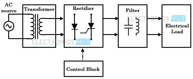
- The essential components in this rectifier include transformer, switching unit, filter and a control block.
- This convertor is used for charging the battery.
- This is the most common charging method for electric vehicles.
DC to DC Convertor -
- A DC to DC convertor is also called chopper is a static device that converts a fixed input DC voltage to variable DC output or a fixed DC output of different magnitude (which can be lower or higher) than input value.
- The block diagram of a DC chopper is shown in figure below.
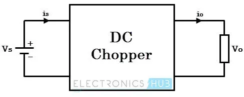
- The chopper circuit is connected between DC input source and DC load.
- This chopper consists of power electronic switching devices such as thyristors which are connected in such a way that they produce required DC voltage to the load.
- EVs use two different power systems, a high voltage battery for traction and a low voltage for supplying power to sensor and other equipments.
- The on-board DC to DC convertor must be bi-directional and very efficient as well as highly reliable.
DC to AC Convertor -
- A DC to AC convertor, also known as Invertor, a static device that converts fixed DC supply voltage to variable AC voltage.
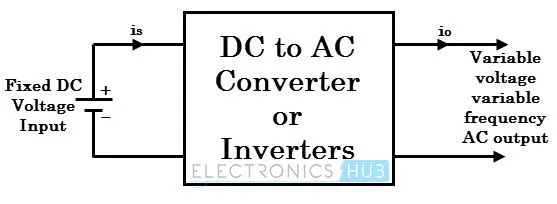
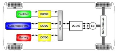
- This convertor is between battery and motor.
- It converts the dc current from the battery to ac, as this ac is used by other devices such as the traction motor and coolant pump.
The convertors used in electric vehicle is shown below -
-------------------------------------------------------------------------------------------------------------------------------
Objective -
To calculate the EV steady state speed if duty cycle is 70% for the given model -
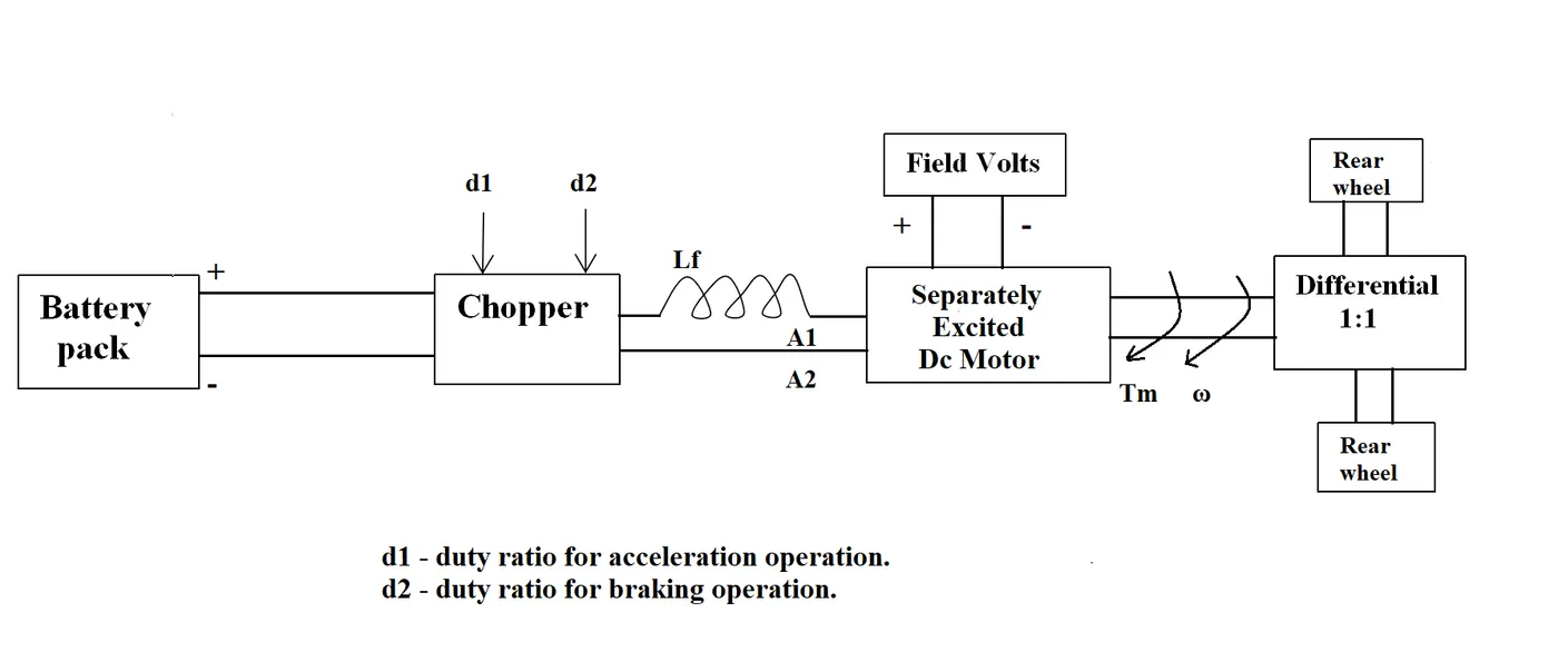
Given Parameters -
- Battery Pack Voltage = 72 V
-
Motor and Controller Parameters :
-
Rated Armature voltage = 72 V
-
Rated armature current = 400 A
-
Ra = 0.5Ω, KΦ = 0.7 Volt second
-
Chopper Switching frequency = 400 Hz
-
-
The vehicle speed-torque characteristics are given by the below equation -
`T = 24.7 + 0.0051omega^2`
- Duty cycle = 70% = 0.70
Calculations -
The given torque speed characteristics is
`T = 24.7 + 0.0051omega^2` .................(1)
We know that,
`T = (V_a*k_phi)/R_a - (k_phi^2.omega)/R_a` .................(2)
where T is the torque,
`V_a` is the armature voltage,
`R_a` is the armature resistance,
`omega` is the motor speed (rad/sec)
`k_phi` is the motor constant
Vehicle output voltage, V = `V_a`* duty cycle
V = 72 * 0.70 = 50.4 V
Putting the given values in equation (2),
`T = (50.4 * 0.7)/0.5 - (((0.7)^2*omega)/0.5)`
`T = 70.56 -0.98omega` ..................(3)
On comparing equation (1) and (3)
`24.7 + 0.0051omega^2` = `70.56 - 0.98omega`
`0.0051omega^2 +0.98omega - 45.86 = 0`
On solving for the value of `omega`, we get
`omega = 38.915 and -231.072`
As the speed never be negative, so
`omega = 38.915` rad/sec
Result -
The steady state speed is 38.915 rad/sec.
------------------------------------------------------------------------------------------------------------------------------------------------------
Objective -
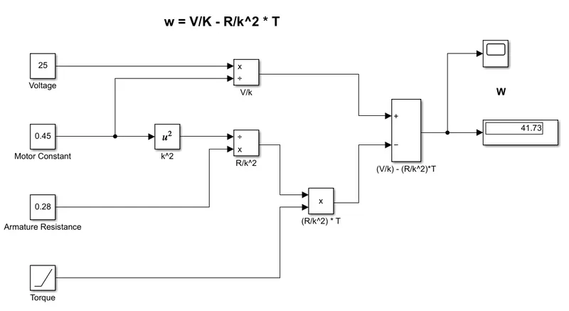
To develop a mathematical model of a DC Motor for the below equation using Simulink.
`omega = V/k_phi - R_a/k_phi^2 *T`
Model -
The given equation is implemented by using basic simulink blocks as given below -
Input Parameters -
- Voltage, V = 25
- Motor Constant, k = 0.45
- Armature Resistance, R = 0.28
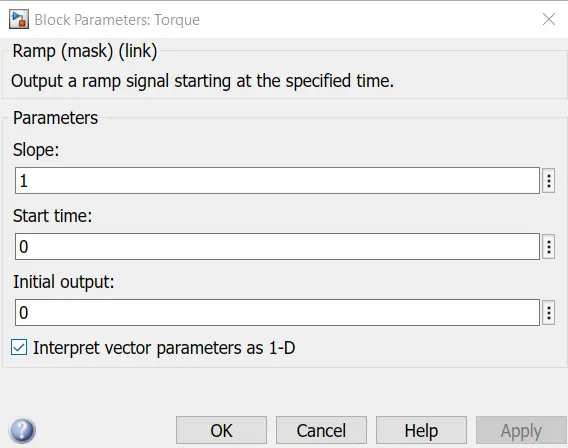
- Torque, T is given using ramp block
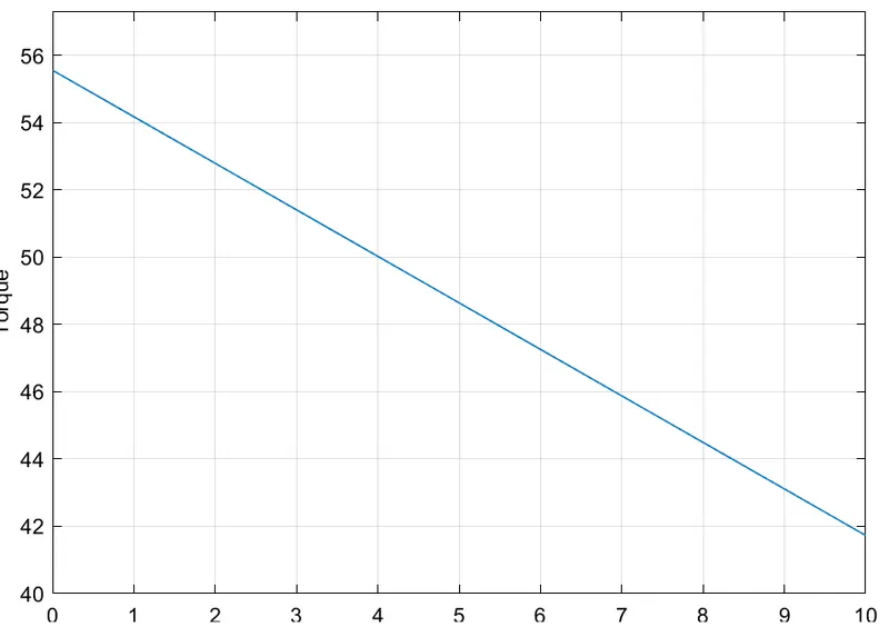
Output -
-------------------------------------------------------------------------------------------------------------------------------------------------------
Objective -
To explain in brief about author’s perspective in the article Induction vs DC Brushless Motors by Wally Rippel, Tesla
Explanation -
- In this article, Wally Rippel talk about the dominance of IC Engines in automobile industry and the idea of using batteries, motors, controllers for electric vehicle.
- He also write about the evolution of technology for batteries as lead-acid battery replaced by lithium batteries, dc brush motors replaced by dc brushless and induction motors and contactors by modulating invertors in the "One Size Does Not Fit All" section.
- In the "A Closer Look" paragraph, he give information about how the dc brushless motor and induction motor works and the difference between them and the three phase induction motor.
- In the "Brushless or Induction?" section, he tells about the similarities of dc brushless motor and induction motor, also talks about the advantages of dc brushless motor over induction motor and advantages of induction motor over dc brushless motor.
- In the same section he listed the limitations and disadvantages of dc brushless motor and induction motor for using in electric vehicle.
- In the last section of article "Still No Winner", he concluded that DC brushless drives will likely continue to dominate in the hybrid and coming plug-in hybrid markets, and that induction drives will likely maintain dominance for the high-performance pure electrics.
- He also raises a question, "what will happen as hybrids become more electrically intensive and as their performance levels increase?"
- He also gave a speculation that so much of the hardware is common for both drives could mean that we will see induction and DC brushless live and work side by side during the coming golden era of hybrid and electric vehicles.