Simulink - Week - 4
Objective -
To implement control logic of a “washing machine” using Stateflow as per given sequence:
- If the power supply is available, the system gets activated.
- If the Water supply is not available, stop the process & indicate through LED.
- Soaking time should be 200s followed by Washing time of 100s.
- Then rinsing happens for next 20s & dryer runs for 50s.
- After all the processes have completed turn on the finished LED.
Assumptions -
- Simulation Time is 450 seconds.
Model -
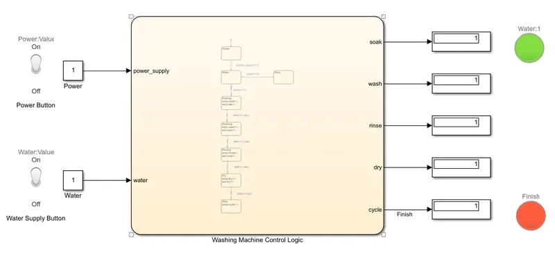
The model for washing machine control logic is given below -
Stateflow Chart -
The stateflow chart used in the model is given below -
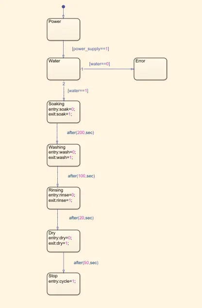
Chart Parameters -
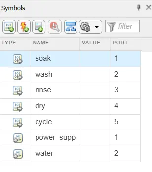
- Input Parameters - power_supply, water.
- Output Parameters - soak, wash, rinse, dry, cycle.
Explanation -
- The power supply and water supply is given using toggle switch which provide value '1' when "ON" and value '0' when "OFF" condition.
- When power supply is "OFF" then the logic does not activates, it activates only when the power supply is in "ON" condition.
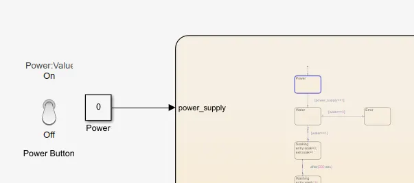
- As when power is OFF, state the logic remains at first state i.e. at power state.
- To go to next state condition of power "ON" should be fulfill.
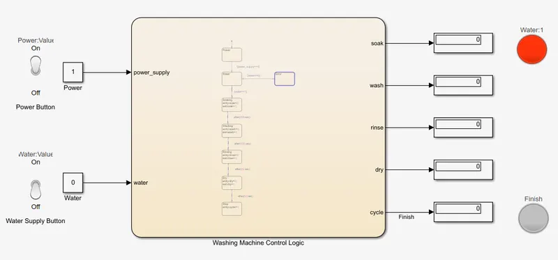
- When Water supply is given then the logic process to the next state otherwise it will goto error state and LED will show "RED" colour and the process halts.
- When the water supply is given, the LED will show "GREEN" colour and the logic will process to the next state.
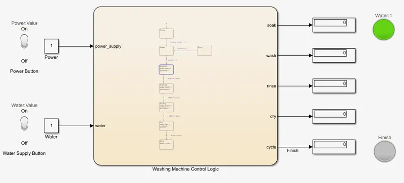
- The next state is Soaking, here the logic stays for 200 seconds as the delay time to go to th next state is given as 200 seconds.
- After 200 seconds, washing state process for 100 seconds as delay time is 100 seconds.
- After washing state, rinsing state process for 20 seconds.
- After rinsing state, dry state process for 50 seconds.
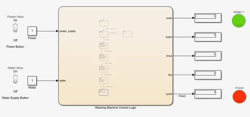
- When the above process completed the logic process the Stop state, then the Finish LED lit up in "RED" colour.
Conclusion -
- We have succesfully implement the Washing Machine Control Logic using Stateflow.
--------------------------------------------------------------------------------------------------------------------------------------------------
Objective -
To make a Simulink chart for the “Gear shift” logic as per below conditions:
| Speed Range(kmph) | Gear |
| 0 to 15 | 1 |
| 16 to 25 | 2 |
| 26 to 40 | 3 |
| 41 to 60 | 4 |
| Above 61 | 5 |
- Give speed input while the simulation is running & display the gear number.
Assumptions -
- Simulation Time is set at infinity i.e. inf.
Model -
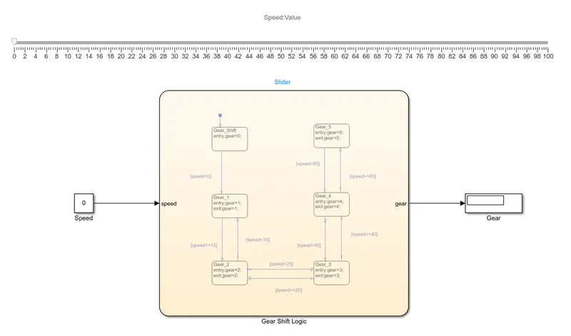
The model for gear shift logic is given below -
Stateflow Chart -
The stateflow chart for gear shift logic is given below -
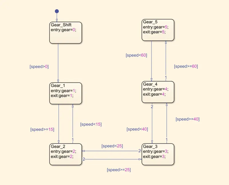
Chart Parameters -
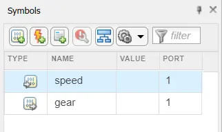
- Input Parameter - speed.
- Output Parameter - gear.
Explanation -
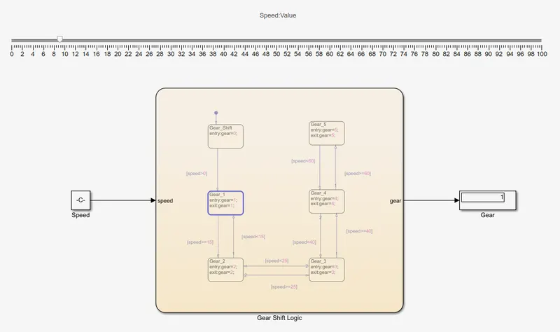
- The Slider block is used to provide input as speed.
- This slider block is connected to Constant block which is connected to the chart input.
- A Display block is provided to know the gear value for the given input speed.
- During the running of simulation, as the slider input vary gear value changes.
- When the slider input value increases from 0, i.e. speed>0, state of Gear_1 is processed.
- During this state display shows the value 1.
- When the speed value exceeds 15, i.e. speed>15, the next state Gear_2 is processed.
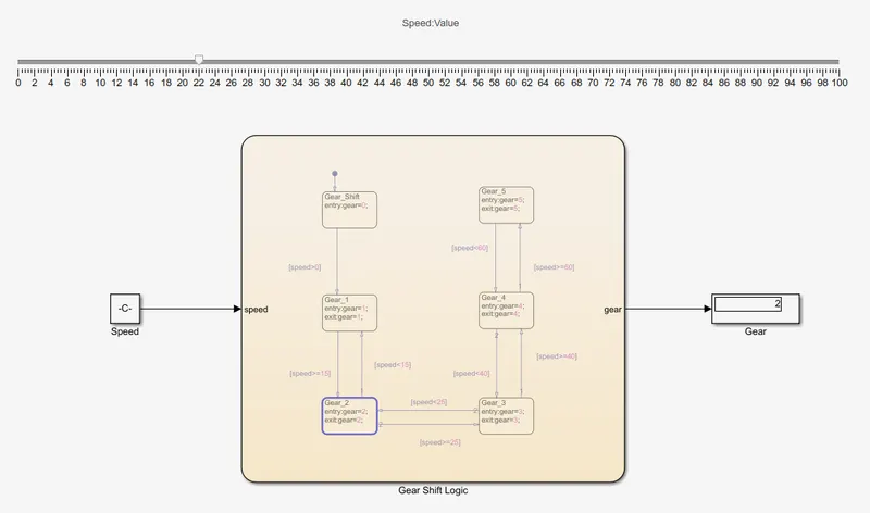
- During this state display shows the value 2.
- When the speed falls below 15, i.e. speed<15, state of Gear_1 will process.
- Gear_2 state will process for the speed between 15 to 25.
- When the speed value exceeds 25, i.e. speed>25, next state Gear_3 state will process.
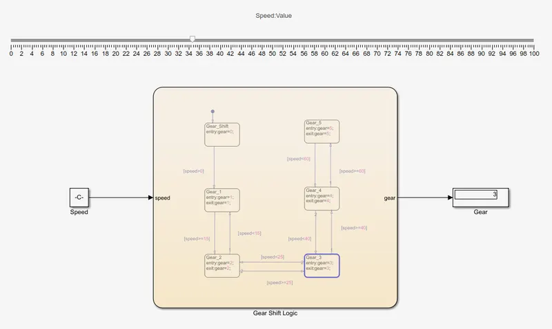
- During this state display will show the value of 3.
- When the speed falls below 25, i.e. speed<25, Gear_2 state will process.
- This Gear_3 state will process for the speed range of 25 to 40.
- When the speed value becomes greater than 40, i.e. speed>40, the next state of Gear_4 will process.
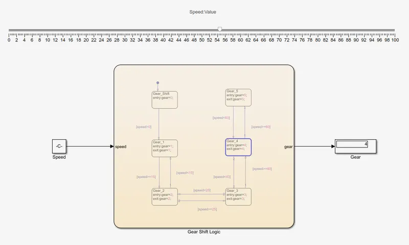
- During this state display will show the value of 4.
- When the speed falls below 40, i.e. speed<40, Gear_3 state will process.
- This Gear_4 state will process for the speed range of 40 to 60.
- When the speed value becomes greater than 60, i.e. speed>60, the next state of Gear_5 will process.
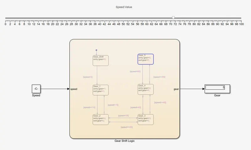
- During this state display will show the value of 5.
- When the speed falls below 60, i.e. speed<60, Gear_4 state will process.
- This Gear_5 state will process for the speed range of above 60.
During the simulation of this Gaer Shift logic as gear value shown in display vary acoording to the above cases of speed range.
Conclusion -
We have succesfully implement the Gear Shift Logic using Stateflow.