Week 7 State of charge estimation
Problem:-01
The Battery Management system is an embedded system technique designed to monitor the battery's overall performance and health.
Major functioning of BMS can be understood by following points:-
1. Protects the battery cells from damage
2. Prolongs the life of a battery
3. Co-ordinate with the controller to do optimal use of battery energy
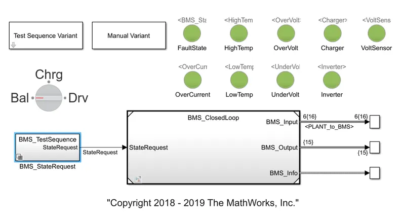
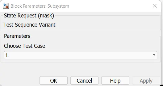
We will now focus our study on a Lithium battery BMS. The given model is designed to work in three conditions which are named as test cases.
It has a dashboard containing LED lights to inform the user about the present conditions of the battery packs.
Basically, the BMS has three modes of functioning namely:- Driving, balancing and Charging.
CASE:- 1
 .
.
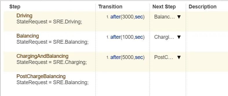
For this condition total simulation is segmented into three divisions.
1. Total simulation duration= 20000 seconds.
2. For the first 3000 secs, the model is in driving condition. This implies that the battery pack would be served by a discharging current which will provide the discharging.
3. For the next 1000 secs, the model would do the balancing of the battery pack.
4. After that, for the next 5000 secs, the battery pack would be in charging conditions.
5. For the remaining time, the battery pack would be in a standby state.
Results:-
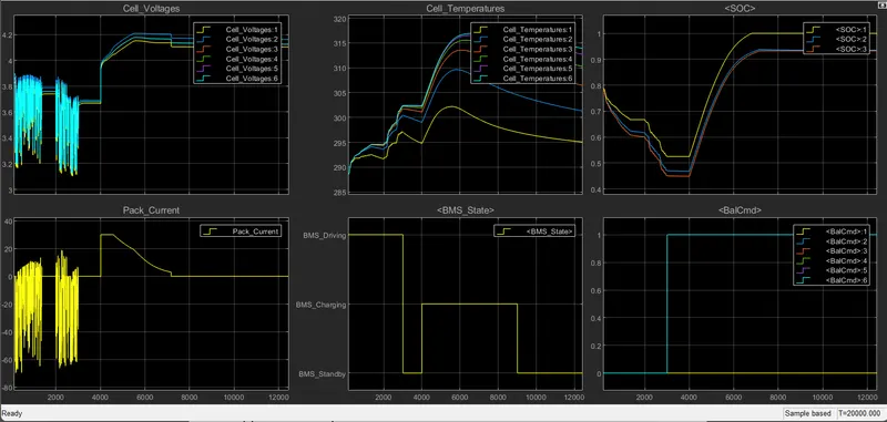
As the model is in discharging for first 3000 secs, we can observe for this duration SOC is decreasing.
Also during this duration, the cell temperatures are rising due to the current flow.
There is a variable pack current during this period.
For next 1000 sec the SOC remains constant due to the balancing state. Pack current becomes zero.
As the current flow stops heat source is eliminated which leads to constant or decreasing temperature
during this duartion.
After this state, charging initiates which leads to an increase in SOC and a current flow.
Due to current flow, the cell temperatures start to increase along with the cell voltage.
During this state, none of the faults were obtained so all the indicators of the dashboard are green.
CASE:- 02
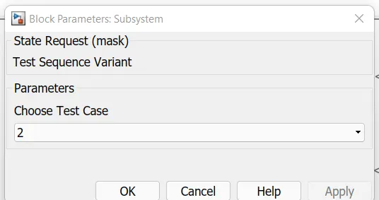
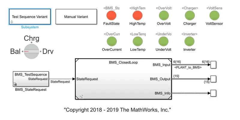
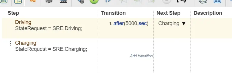
In this case , for first 5000 seconds the model is in driving state. After that it shifts to the charging state.
Since there is continuous flow of current in both the states, current flow is never stopeed.
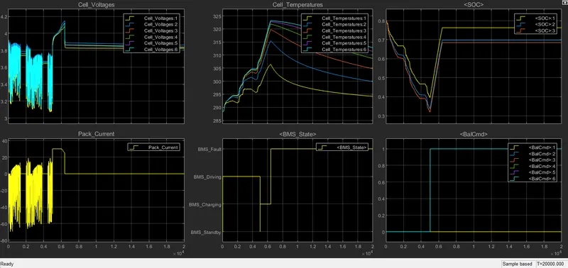
Results
1. SOC is continuously decresing till 5000sec.
2. After 5000 sec the model has faced a fault due to which it goes into fault state.
3. Reason of fault is the temperatre rise of the cells due to continuous flow of high rated currents.
4. After the fault is detected SOC remains constant.
CASE:- 03
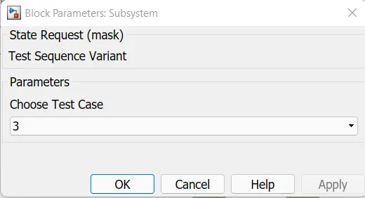
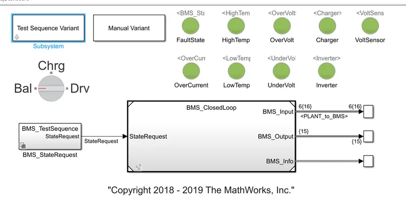

In this case, the model remains in a charging state from start to end time without any state change.
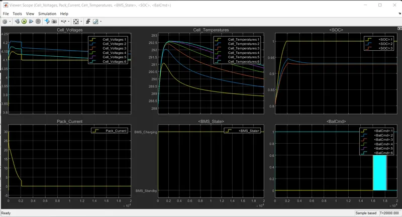
Results
1. After 2000 secs the SOC remains constant .
2. Current flow seizes after 2000 secs as SOC saturates.
Problem:-02
Columb counting is the SOC determination method in which the discharging current is measured and integrated over time .
In this method, SOC(t) is calculated from discharging current I(t) and previously measured SOC values, SOC(t-1).
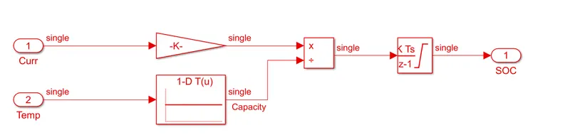
`SOC(t) = SOC(t-1)+ (I(t)*delta t)/(Qn)`
`nbsp;
The given formula is applied in Simulink using blocks as shown below. Here capacity is calculated using a lookup table.
By inputting the temperature we are being served with the capacity of battery cells`
# This method is very easy to implement and very ecnomical.
# Drawback to this method is, it doesn't consider battery chemistry.