Modelling Contol Unit for Washing Machine and Gear transmission using SIMULINK
Modelling Contol Unit for Washing Machine and Gear transmission using SIMULINK
OBJECTIVE:-
In this project the motive was to design two control units using simulunk blocks. The two sysytem on which studies are based:-
1. Washing machine Control Unit
2. Vehicle gear shift
we have to design a stateflow chart on simulink such thet two show the stepwise functioning of each sysytem mentioned above.
Implementation control logic of a “Washing Machine” using Stateflow
Washing Machine is a common household electrical appliance used for washing clothes. Its functioning comprises of different stepwise workings.
Different functioning of a washing cycle of the washing machine are:-
- Soaking
- washing
- rinsing
- drying
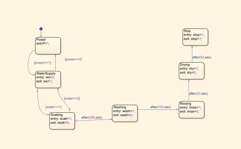
To design the control unit we have started with first creating the logic for its functioning in the stateflow. As per the given working conditions we designed the chart on which the washing machine control unit will function.
Conditions:-
- activate the machine based on power supply
- check for water supply
- soak for 200s
- wash for 100s
- rinsing 20s
- drying 50s
- finish the process
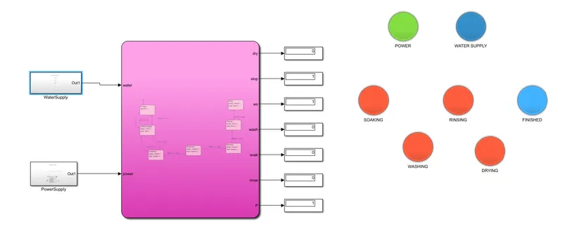
Simulink Model:-
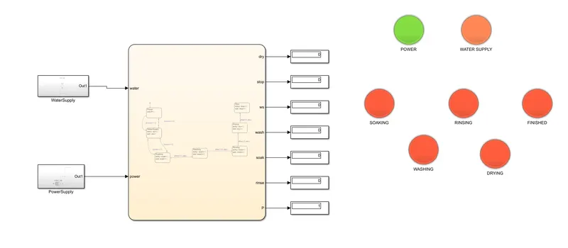
Stateflow chart:-
Blocks Used:-
- constant
- display
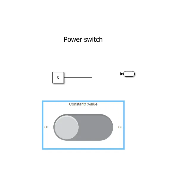
- toggle switch
- slider switch
- lamps
- stateflow
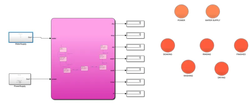
Results:
- when power supply is of and water supply is on or off:-
ii. when power supply is on and water supply is off:-
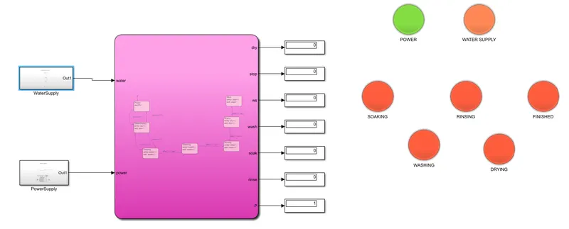
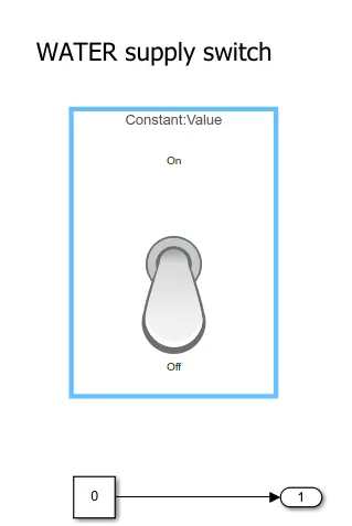
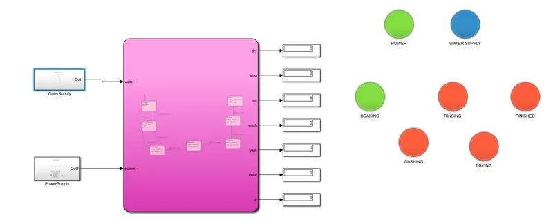
iii. some cases of working during on conditions of both the power and water supply
a. at 100 sec
b. at 250 sec
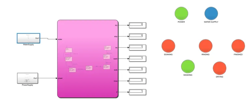
c. after completion
Simulink chart for the “Gear shift” logic
Gear is the mechanism of applying accurate balance between need and supply in needed torque and speed during motion of any vehicle.
Engine provides a smooth revolutions to crankshaft, it is the gear mechanism which supplies rpm and torque to the accurate amount to output shaft.
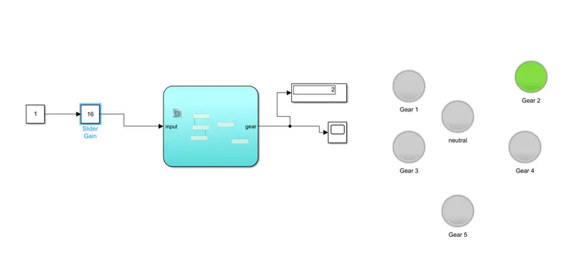
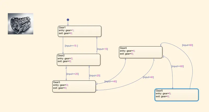
We are designing a control unit for automatic gear transmission , which will be automatically shifting gears according to the speed input.
We have laid full logic of gear transmission in the stateflow chart and output has been shown in form of lamps. Their blinking will signifies the vehicle is in which gear shift.
Blocks used:-
- constant
- display
- slider gain
- stateflow
- lamp
- scope
Simulink Model:-
Stateflow Chart:-
RESULTS:-
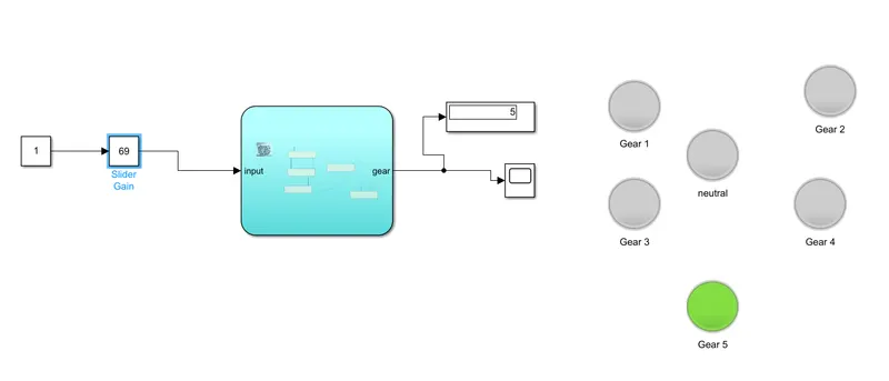
Underying are some snaps of the simulation at different speed ranges.
1. Speed between 10-20 km/hr
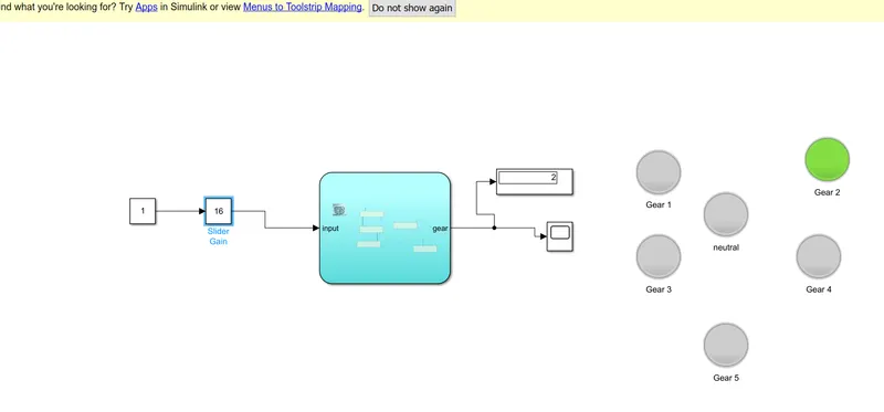
2. Speed between 30-40 km/hr
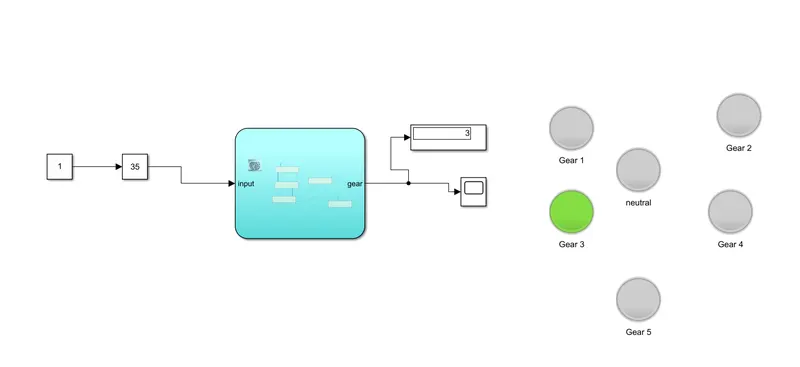
3. Speed above 61 km/hr
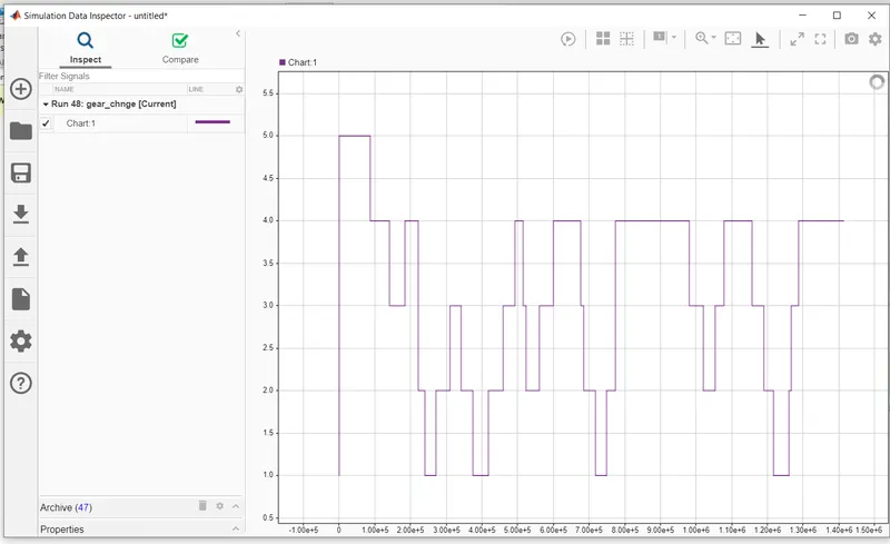
Graph of gear vs time with respect to speed given:-
Simulation Animation Video:-
CONCLUSION:-
In this project I came to know about modelling of different control units have been designed. This was a very intresting project as I gather information about real life application of SIMULINK.
It took my brain in finding the logic for each sysytem and make them run on the simulations. At last with a lot of hurculean efforts I enable this project to be completed.
It gives me inner delightment by working on such wonderful projects.