Week 7 State of charge estimation
Study 1:-
Simulate the 3 test cases from Harness dashboard:-
Simulation Block:-
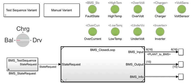
The dashboard contains a Test Sequence Varient which contains three test sequences among which a test sequence can be selected and simulation can be made or a manual sequence can be selected through knob in the dashboard which will be provided through the BMS_Test sequence and the stateRequest is provided to the BMS_Closed loop and the outputs are connected to the scope to view the result.
BMS_closed loop:-
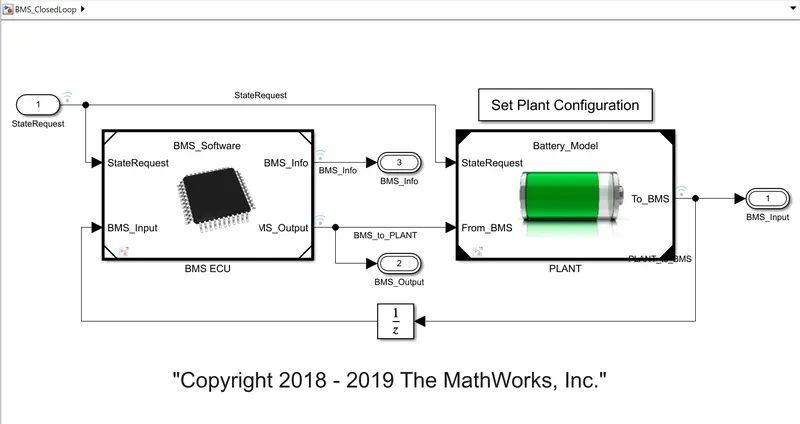
The BMS_Closed loop contains two subsytems BMS ECU and Plant unit
The output from the plant unit is given as an input feedback and the state request which is the test sequence to be performed is also provided as input to BMS ECU
The BMS ECU provides command to the plant and the test sequence is also given as input and the output from the BMS_closed loop block are the BMS_input, BMS_output and BMS_info.
BMS ECU:-
Here there are state_Machine, SOC Estimation, Balancing Logic, current_power_limit_calc and the StateRequest signal is provided as input to the current_power_limit_calc and a higher and lower limits are set inorder to avoid overcharging or over discharging of power
The statemachine will process the input and sends command accordingly as per the requirement such as charging current limit and charging time it estimates the value according to the state request.
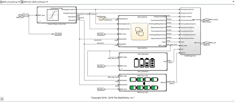
SOC Estimations are made to inorder to monitor the state of charge of the battery and balancing logics are made to proper charging and discharging inorder to avoid cell damage due to overcharging or temperature rise or deep discharge of battery.
Plant:-
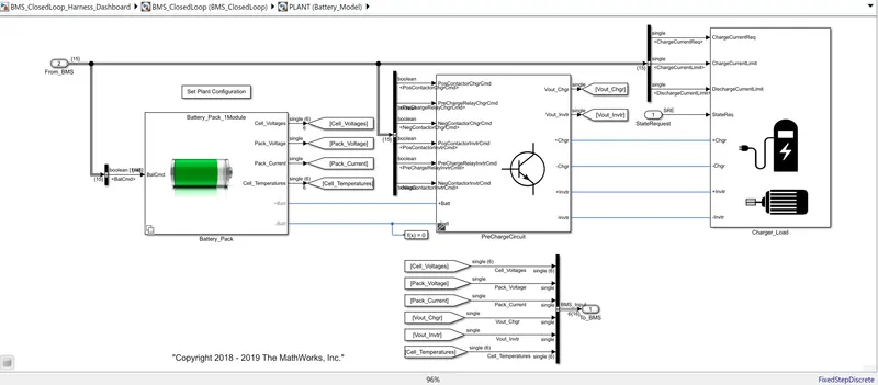
The plant contains the battery pack module and precharge circuit and charger load
Test Case 1:-
By selecting test case 1 Test Sequence Varient block we will perform the simulation to identify the result
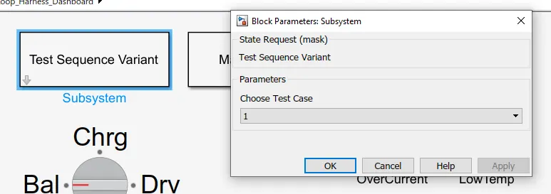
It can be checked by double clicking on the BMS_TestSequence block
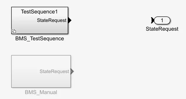
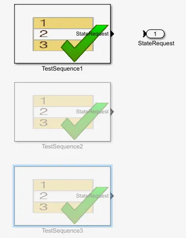
To view the test condition we need to double click on test sequence 1 here we are going to perform the following
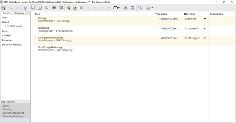
Here the driving cycle takes place for a period of 3000 secs and then balancing cycle for a period of 1000 secs and then chargingAnd balancing cycle for 5000 secs and finally post charging balancing takes place untill the end of simulation which is set to 20000 secs.
Result:-
The simulation is run for a period of 20000 secs and the scope is observed.
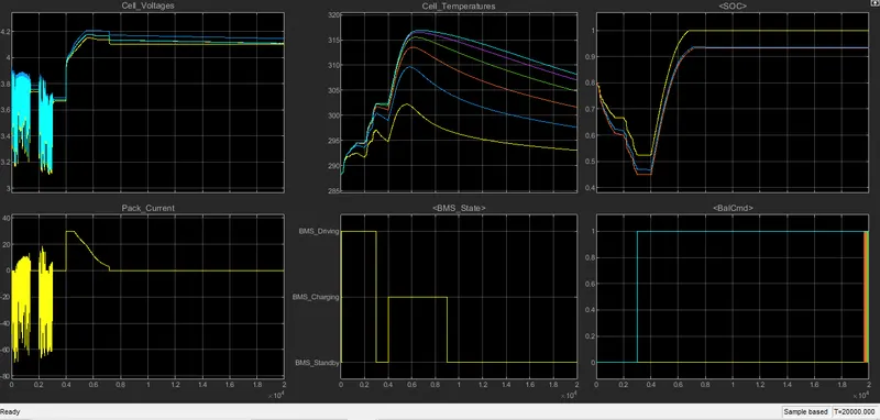
Time Period - 0 to 3000 sec - Driving
Cell Voltage and Pack current plot states that the voltage varies from 3.15V to 3.9 V & -60 to 20 and which indicates discharging occurs and the fluction in current and voltage indicates regenerative braking has taken place during the drive cycle.
Here the negative current indicates discharging and positive current indicates charging due to regenerative braking
The Cell temperature increases gradually and reaches 303 K
SOC - Discharging during this period, Intially it is in 0.8 and it nearly decreases to 0.45 during the end of driving cycle.
BMS State - Discharge state.
Balancing cell is at 0 during this cycle.
Time period - 3000 to 4000 sec - Balancing
Cell balancing taken place during this time and loads are in standby mode and we can observe that the voltages are at 3.7 V and are constant and current is 0 during this period.
The cell temperatures are slightly reduced since there is no current flow.
SOC is constant and maintains at 0.45 as cell balncing is taking place.
BMS State - Standby Mode.
Balancing cell is at 1 during this cycle sincing balancing of cells occurs.
Time Period - 4000 to 9000 sec - Charging and Cell Balancing
Cell Voltage and Pack Current - Cell voltage raises from 3.7V to 4.2 V with a pack current raising from 0 to 30 A and then remains constant for some time and once the voltage reaches 4.2 V the current gradually reduces to 2.6 A.
Cell Temperature - Temperature increases exponentially until the current flow reduces and it raises upto 317K.
SOC - The battery is in charging that is in CC and CV mode of charging.
BMS State - BMS Charging
Balcmd - is at 1 during this stage and few cells are at 0.
Time Period - after 9000 sec - Post Charge balancing:
Cell voltage and Pack Current - Pack current is at 0A and cell voltage are balancing with each other to reach a similar voltage range.
Cell temperature - The increase in temperature during charging is slowly cooled down during this cycle and reaches the ambient temperature.
SOC - 0.94 and it remains the same in this cycle.
BMS State - Standby
Balcmd - is 1 since balancing taking place and fewer cells are at 0 state since they must have a lesser voltage range or capacity.
Test Case 2:-
The test sequence 2 is selected and screenshoot as follows,
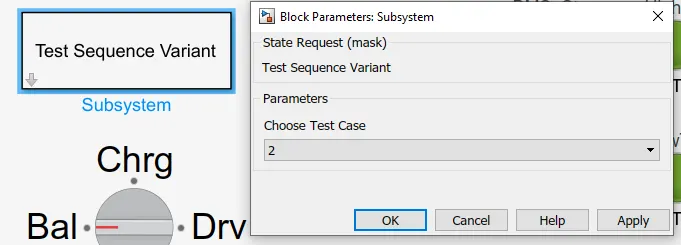
The sequence will be updated to second as shown in below image.
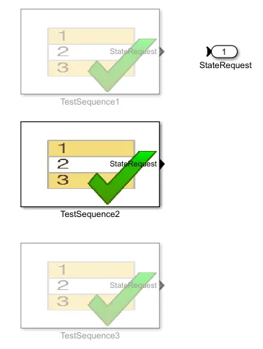
The test conditions are as shown in the below image
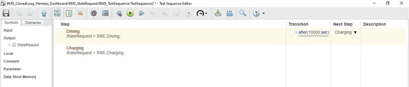
Here there are only two modes of operation one is driving which is taking place for a period of 10000 seconds and then the charging begins until the simulation takes place.
Results:-
The simulation is run for a time period of 20000 seconds and the result is observed.
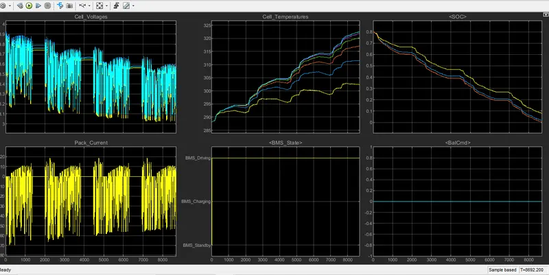
Here the plot are taken for the drive cycle as the battery is drained completely the vehicle cannot be moved further to complete the cycle.
Cell Voltage & Pack current - Cell voltage varies from 3.01V to 3.9V since it reaches the cutoff voltage at 9000 seconds i.e the battery is drained completely and the pack current discharge maximum current of 70 A which is negative in plot whereas slight charging occurs due to regenerative braking during the run.
Cell Temperature - Cell temperature increases during this cycle from 288K to 323K
SOC - It reduces from 80% to 0% in 9000 seconds before the drive mode completion time.
BMS State - Driving
Balcmd - At 0 since no balancing taken place during this cycle.
Test Case 3:-
The test sequence 3 is selected and screenshoot as follows,
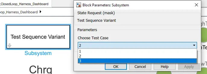
The sequence will be updated to third as shown in below image.
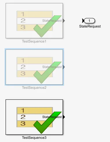
The test conditions are as shown in the below image
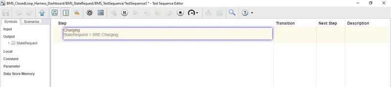
Here there are only one modes of operation which is charging.
Results:-
The simulation is run for a time period of 20000 seconds and the result is observed.
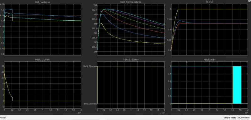
The plots above represents,
Cell Voltage & Pack current - Cell voltage raises from 3.9V to 4.2V and then reaches a constant voltage range of 4.15V and the pack current raises from 0A to 30 A and starts reducing gradually to 2.5A until it is charged fully after battery pack is charged it will cutoff.
Cell Temperature - Cell temperature increases during this cycle untill it is fully charged and then it reduces gradually and reaches ambient temperature.
SOC - It is fully charged at 2000 seconds, the actual state of charge is around 93% which is considered as the full charge.
BMS State - Charging
Balcmd - All cell are trying to balancing and its value is 1 for this mode.
Thus the test are performed and its results are anlysed.
Study 2:-
Coulomb Counting:-
Inorder to find SOC% we are using coulomb counting method.
SOC is defined as rate of charge available to its maximum charge capacity of the battery
The coulomb counting method measures the discharge current from the battery and by intergrating it over time in order to get SOC estimate of the battery which is estimated by comparing the discharge current with previous state of charge which can be given in formula as
`SOC(t) = SOC(t-1)+((I(t))/(Qn)trianglet)`
BMS Implements Coulomb Counting for SOC Estimation:-
Here in the above simulation the Coulomb Counting for SOC Estimation is shown as below
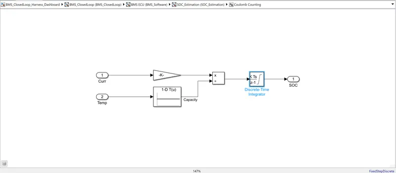
The current discharge from the battery is provided to gain of (1/3600) in order to convert the A into Ah and then the value is divided using the capacity due to temperature change and the resultant is integrated with a gain value 1 and sample time -1
DiscreteIntegrator Parameters:-
The saturation limit are set as 0 to 1
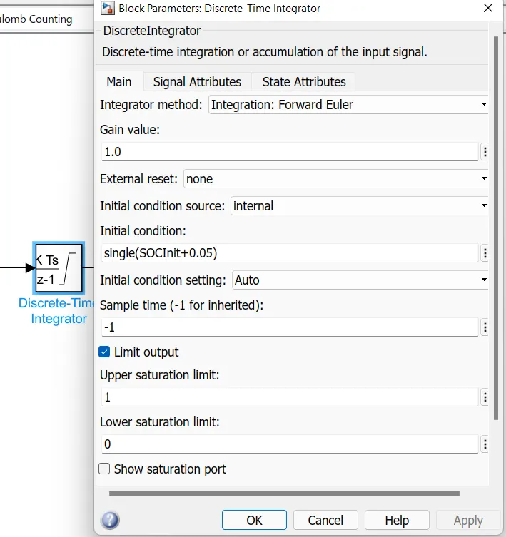
Thus we have seen how BMS Implements Coulomb Counting for SOC Estimation in the the simulation.