Project
Aim:
To study, analyze and prepare a detailed technical report explaining the properties of Baja All Terrain Vehicle (ATV) Model using simulink.
Description:
All Terrain Vehicle (ATV):
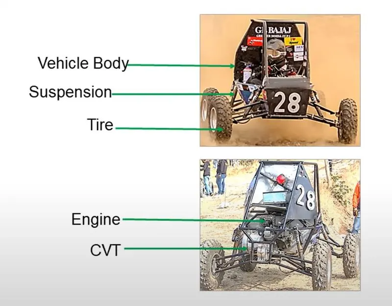
An ATV (All Terrain vehicle) which is also known as quad,Light Utility vehicle which uses low pressure tires along with handle bars for steering control . As its name suggest it is used especially in Offroading since it capacity of offroading is high comparitively and can carry heavy instruments over narrow access region.
CVT:
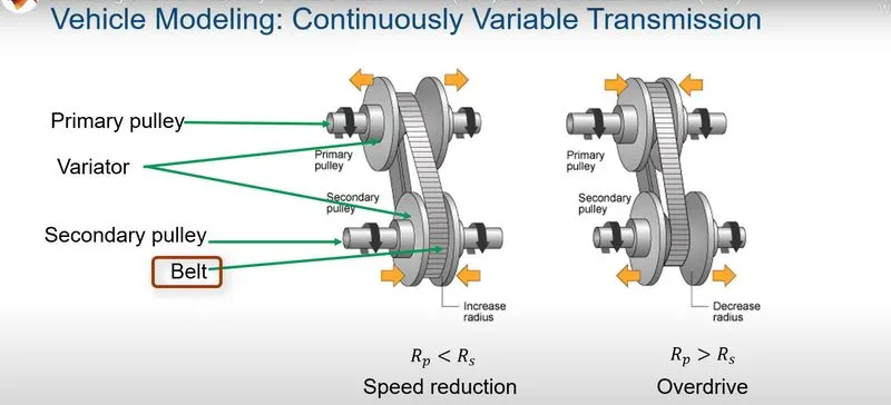
A Continuous variable Transmission (CVT) is an automatic single speed and gearless transmission that can shift through infinite number of gears. It operates on pully system that automatically varies transmission ratio there by providing variablity between high and low gears with no discrete shift.
CTV Provides smoother driving experience,better fuel economy and more power that the usual transmission system.
MODEL 1:-
BAJA ATV Model without Dashboard
The ATV Model with no dashboard is as seen below
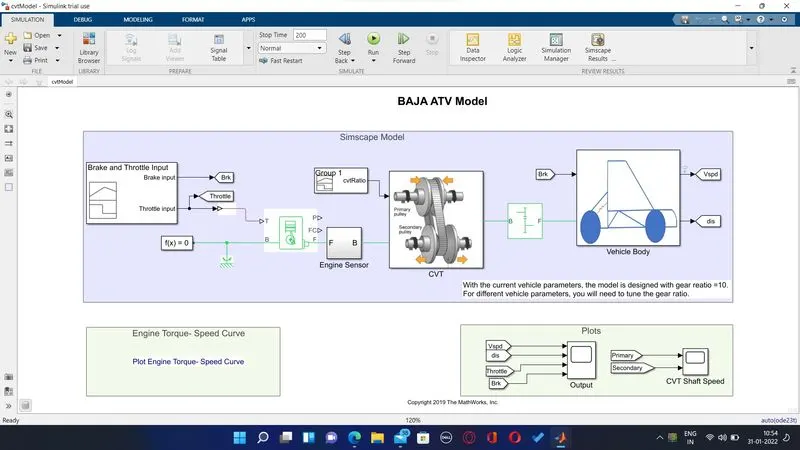
In the above model the input Throttle and brake are provided through signal builder blockwhere the output is provided to the Generic engine block which represents the Engine in the vehicle. The input signal from the Signal builder is as shown below
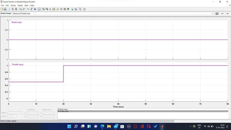
From the above Input signal we can see that the brake signal is set to zero and the throttle signal is set to 0.5 intially and then after 20 sec it is set to 1 for the rest 60 sec.
This signal builder output is provided to the Generic Engine block which is seen as shown below
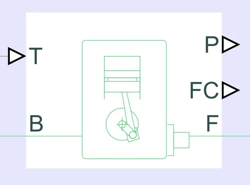
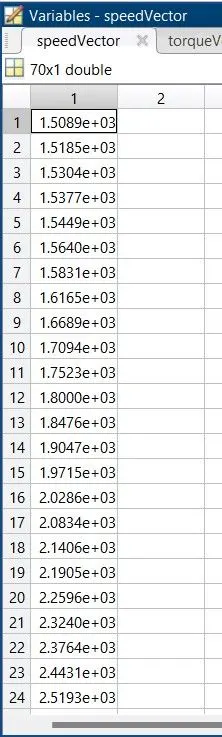
It provides the function of Vehicle Engine , The Signal builder output is provided to the port T of the generic engine block , The ports B and F are mechanical rotation conservation port which is associated with the Crankshaft and engine . The output of the generic engine is provided to engine sensor through port F. This engine was configured with speed vector and torque vector which are data from the actual vehicle in real time, the both speed and torque vector data are provided as below
Speed Vector
Torque Vector
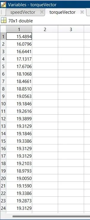
Engine Block parameters the settings was made default inorder to capture the data from the speed and torque vector table and the unit of Speed and Torque are given as RPM and Nm respectively.
The port B of the Generic engine is connected to the rotational reference and the solver configuration and the port F connected to the Engine sensor, The Engine Sensor block is configuration of RPM Sensor which is used in sensing the RPM of the Engine which is the output of generic engine. The Engine sensor configuration is as seen below
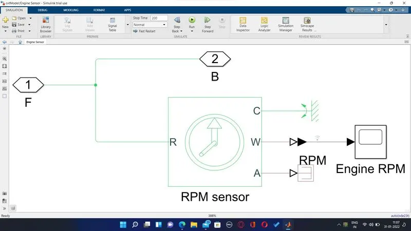
The RPM Sensor is connected to port F of the Generic Engine which is the output of the Generic Engine which is provided as input to the Engine Sensor and the rotational maechanical reference is connected to the C Port of RPM sensor and the output of the RPM sensor is observed using the scope which will display the engine RPM graph and then port B it is connected to CVT transmission block.
The CVT Transmission block is provided with Input from the Engine Sensor B and the gear ratio is provided in form of signal through signal builder , The signal provided as input from the signal builder is as seen in the below image
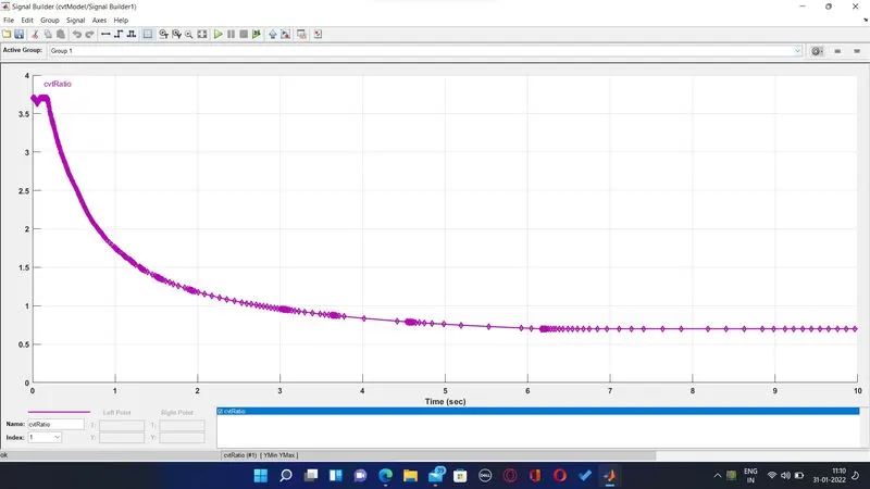
The CVT transmission gear shift ratio is provided as above signal by using the signal builder block.
The CVT block configuaration is as seen below block diagram
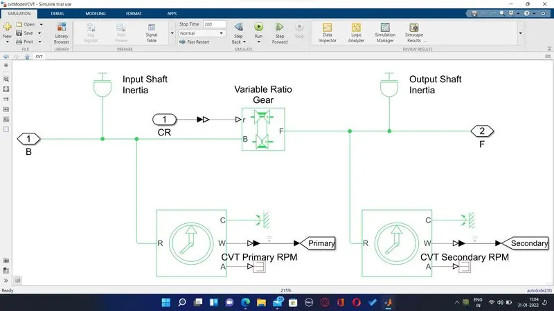
The CVT block there is a variable ratio gear block which is connected to the Signal builder block which represents the gear shift ratio and the Engine RPM which is provided through B port along with the Input shaft inertia and the output of the variable ratio gear is from the F port which is provided as output along with the output shaft Inertia.
The CVT primary RPM and CVT secondary RPM are connected along with rotational reference to C port and port W is the output of the two CVT RPM sensor which is connected to goto tag and are observed through scope and both has R port as Input which comes from B port and F port of variable Ratio gear respectively.
The Port F of the CVT transmission block is connected to Port B of simple gear
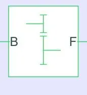
The Simple gear is a fixed ratio gear and the simple gear output port F in turn is connected to vehicle body.
The Port F is connected to the Vehicle body block of the simscape and there are two inputs connected to the vehicle block , The vehicle body block configuration is seen as below
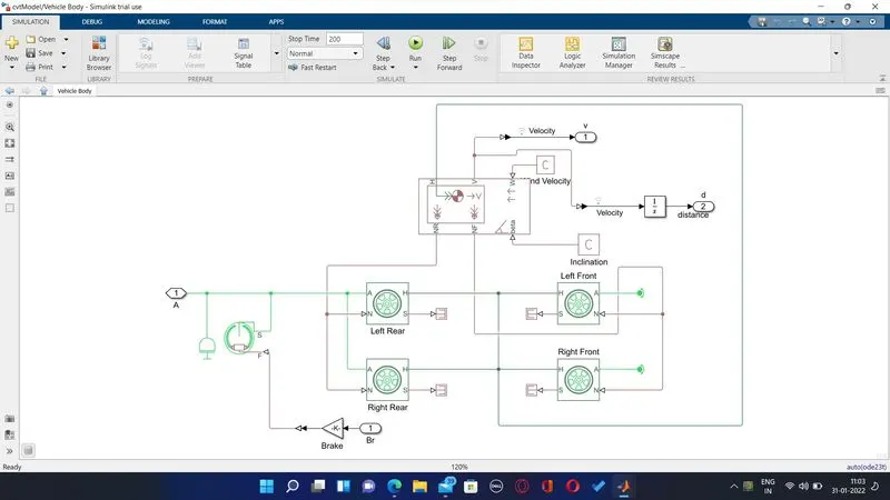
The two inputs connected to the Vehicle body are the Brake input from the signal builder and other is from the simple gear
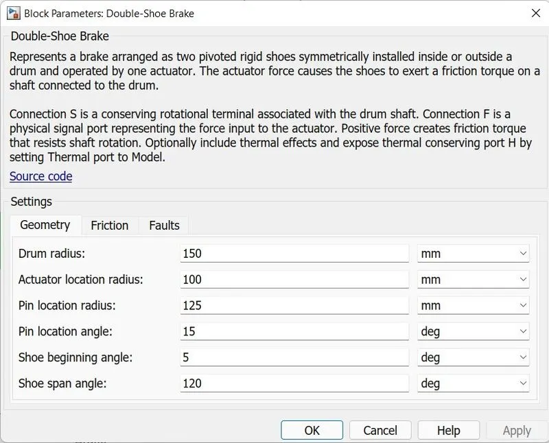
The Simple gear is provided along with the output shaft inertia and the double shoe brake block with brake signal as input is provided to the Rear wheel and then to the front wheel and the wheels are then connected to the vehicle body.
The double Shoe brake block represent the regular drum brake used in most vehicle , The parameter of the double shoe brake is provided as seen in the image below
The vehicle body block is represented as seen below
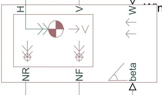
The above block represents two axes of the body and the block consist of the body weight,aerodynamic drag,weight distribution between the axles due to accelaration and the road inclination and road profile are included.
The Port H is mechanical translational conserving port associated with horizontal motion of the body, The traction motion developed by tiresshould be connected to the ports V,NF(Front Wheel)and NR(Rear Wheels) are physical signal output for vehicle velocity which is observed through the scope , Port W and Beta are physical signal input of headwind speed and road inclination angle respectively.
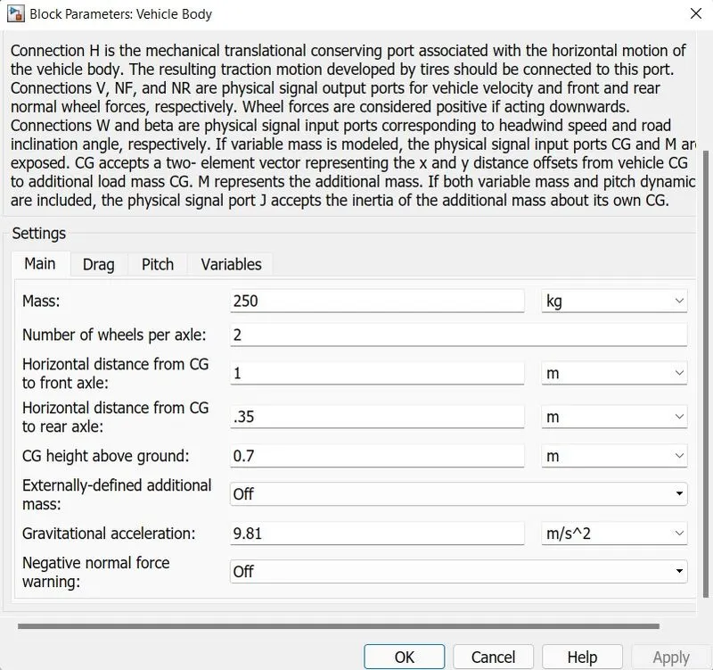
The parameter of Vehicle body is seen as shown below
The Tires connected to the vehicle body are provided through the wheel block which is seen as below
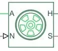
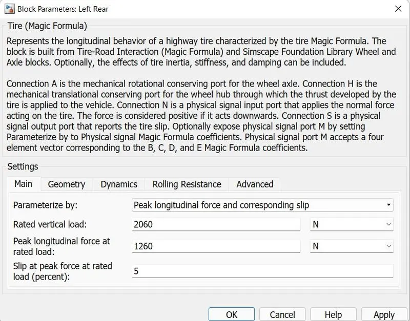
The Parameters of the wheel are provided as shown below here the wheel parameter is provided as peak longitudinal force and corresponding slip , The A port is mechanical rotational conservation port for the wheel axel in which the input signal from are provided from simple gear and brake from signal builder and port H is mechanical translational conservation port for the wheel hub through which the thrust developed by the tire is applied to the vehicle and is in turn connected to the vehicle body Block H Port, N port is a physical signal input that applies normal force acting on the wheel is connected to vehicle body block port NR for rear wheel and NF for front wheel and the S port is a physical signal output port that reports the tire slip.
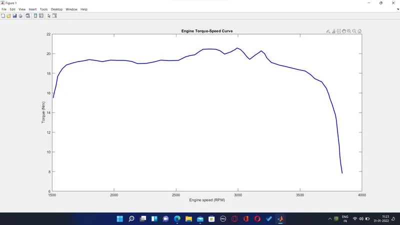
Torque Vs Speed Plot:
The Torque vs Speed plot is provided as below
Output:
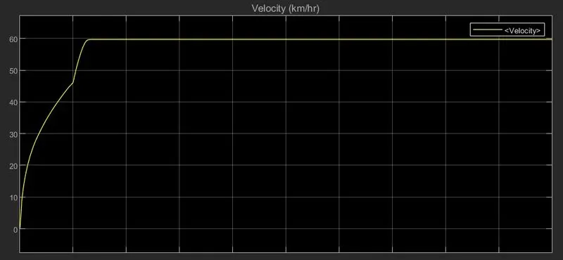
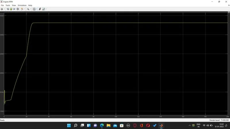
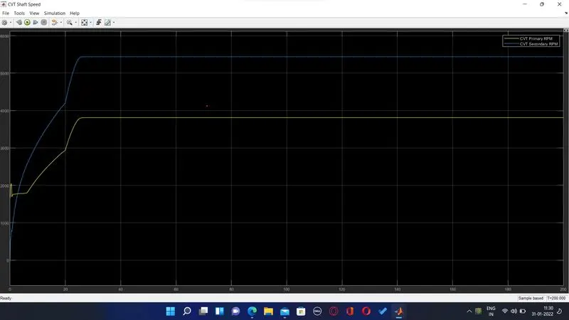
The Velocity of the vehicle for the given throttle and brake input is observed , the RPM of the Engine is also observed and the Primary and Secondary CVT RPM is observed as output through the scope block and which is provided below
Velocity of the Vehicle (km/hr):
Input Signal (Brake & Throttle)

Engine RPM:
Primary & Secondary CVT Shaft RPM
MODEL 2:-
BAJA ATV Model with Dashboard:
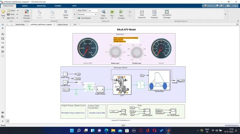
Simulink model of BAJA ATV with dashboard :
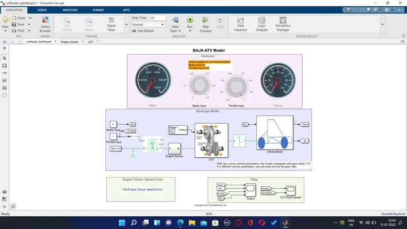
The Simscape model is built with the dashboard and the other part of the system remains the same , the only change is the input is provided manually ie the throttle and brake are provided manually through the knob dashbord block whereas previously the input signal provided through signal builder block.The Engine RPM and Velocity gauge displays the changes happening while the simulation is running and the simulation time is set to inf and it is stopped only we stop the simulation.
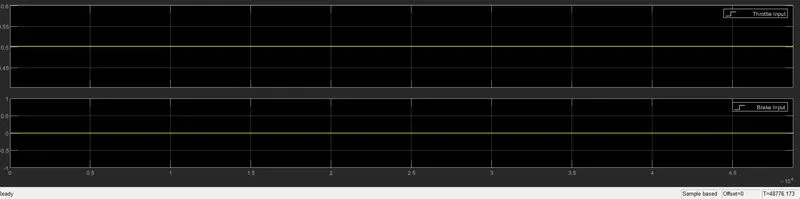
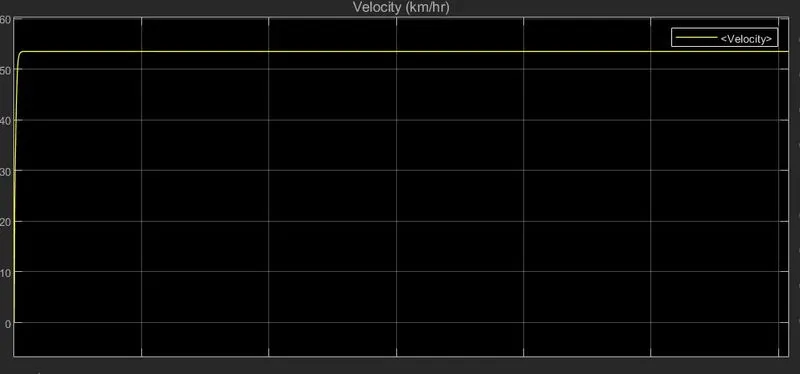
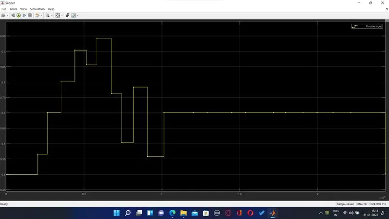
At first by keeping the default condition that is brake at 0 and trottle at 0.5 and the simulation is run and the output of simulation is observed as seen below
Throttle & Brake Input:
Output:
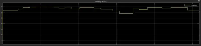
Vehicle Speed:
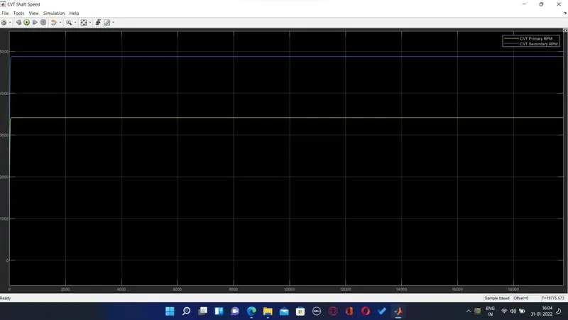
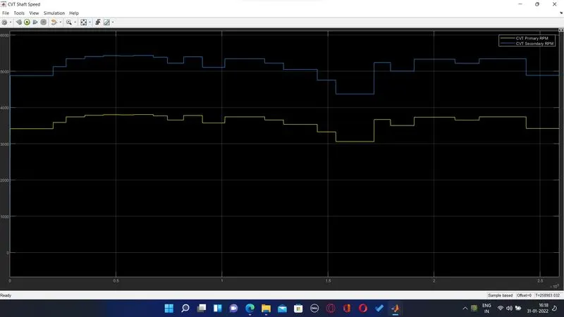
CVT Shaft Speed:
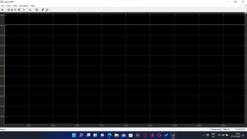
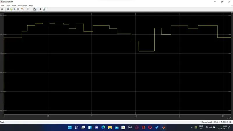
Engine RPM:
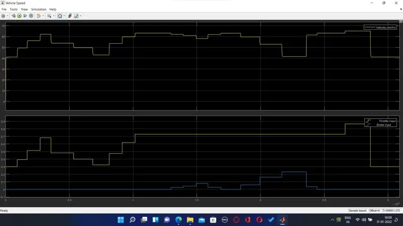
The manual brake and throttle inputs where provided and the output are observed under the scope , the result of simulation is as seen below
Throttle and Brake Input:

Vehicle Speed:
Engine RPM:
CVT Shaft Speed:
MODEL 3:-
BAJA ATV Simulink Models with Lookup Table:
BAJA ATV without Dashboard:
Baja ATV Model with look up table without dashboard is seen as below
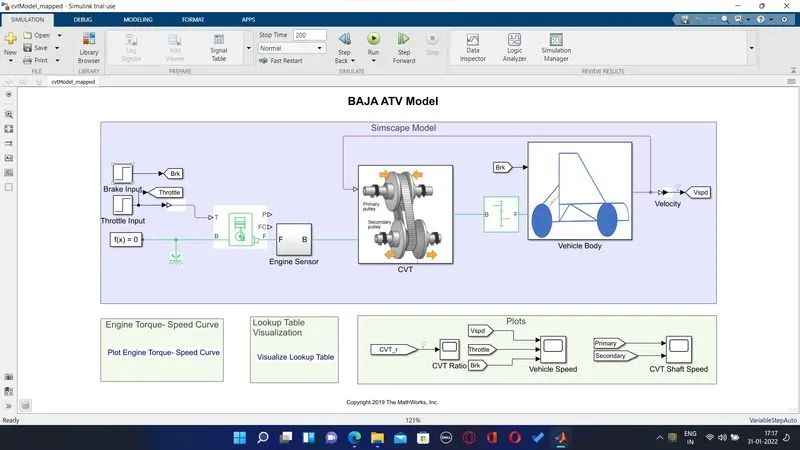
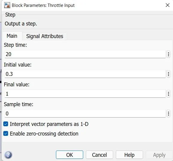
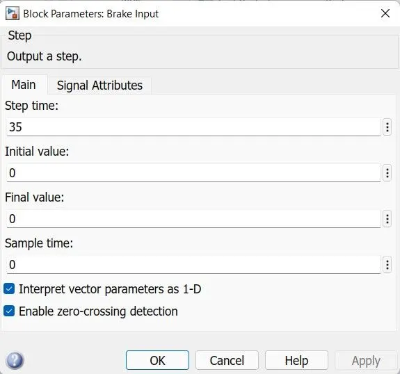
Baja ATV model the Input signal Throttle and brake are provided by using step signal generater block with a run time of 200 sec , with lookup table in the CVT transmission block the input signal provided through the lookuptable which is linked in matlab through external.mat file . Here in this model the throttle and brake input block parameters are as seen below
Throttle Parameters:
Brake Parameters:
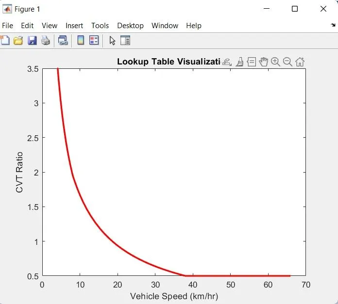
The lookup table is an array of the data that the input maps to output value.The inputs of lookup table can be seen below from the visualise lookup table tab under the model, where the graph is as shown below
The transmission model with lookup table is seen as below
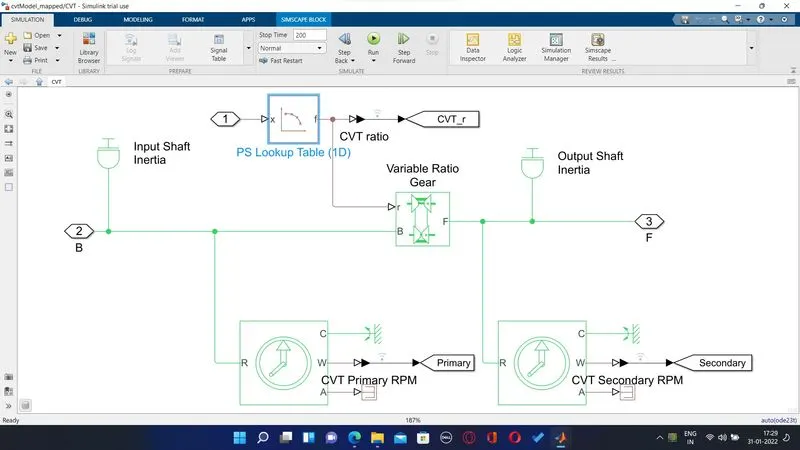
In this model the gear ratio is the input which is provided through lookup table data linked to an external file .mat.
and provided to the variable ratio gear
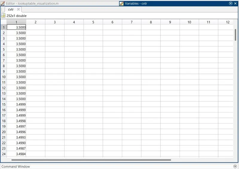
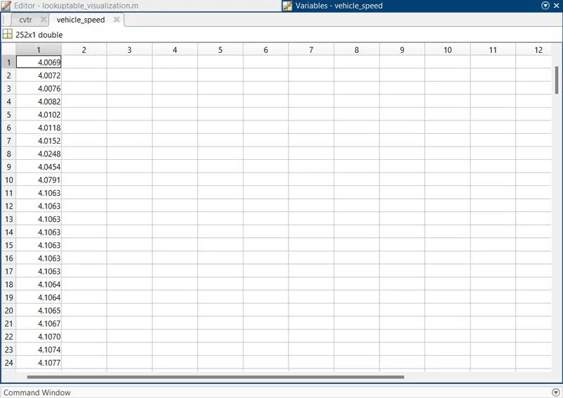
The value of cvtr and vehicle speed are fetched and are as seen below
cvtr Data:
Vehicle speed Data:
Output:
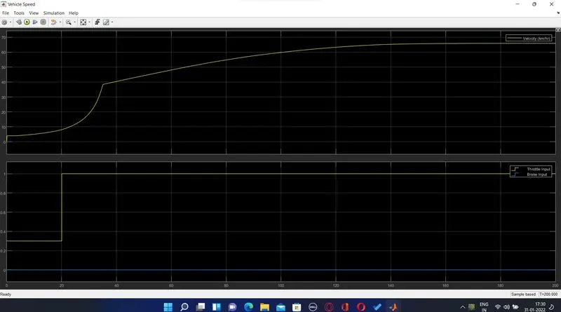
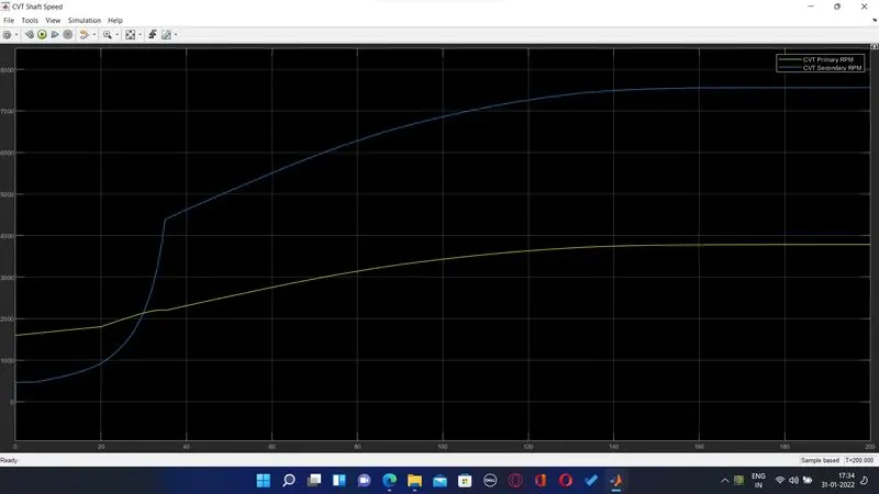
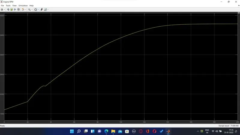
After running the simulation for a period of 200 sec the output is observed in the scope is as shown below
Vehicle Speed:
CVT Shaft:
Engine RPM:
CVT ratio:
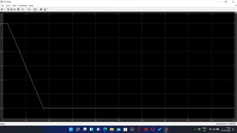
The above output resembles the plot seen previously of CVT ratio vs vehicle speed from lookup table
MODEL 4:-
BAJA ATV with Dashboard with Lookup Table:
Model:
Output:
Vehicle Speed:
CVT Shaft:
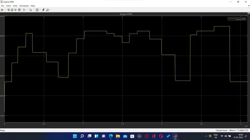
Engine RPM:
CVT Ratio:
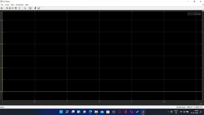
The output of CVT ratio in this model with and without dashboard is observed through the scope.
In Model without dashboard the Throttle and Brake input are predefined whereas in Models with dashboard the throttle and brake input is applied manually.
Result:
1. The simulation for BAJA ATV for model with & without dashboard and lookup table was successful and the result is observed through scope block and viewed graphically and compared.
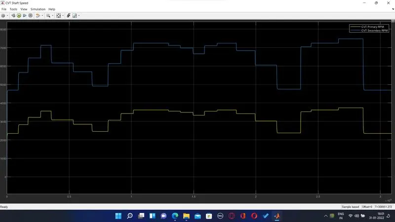
2. CVT shaft RPM , Engine RPM and Velocity are directly proportional to the throttle input and inversely proportional to the brake input.
3. CVT primary shaft speed is greater than secondary Shaft speed as they are directly proportional to their shaft diameter respectively.
4. CVT ratio is directly proportional to torque input and inversely proportional to throttle input.