Week -2
Question 1:-
Simulink Model of Doorbell using solenoid block:-
Doorbell Connection Diagram:
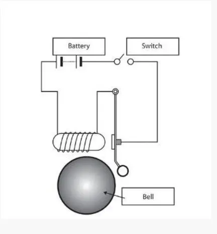
The above provided image explains the working of doorbell, when the switch is closed the electromagnet recieves the electrical power from the battery and which in turn produces a magnetic flux to pull the metal arm to hit the bell producing sound ,where the electrical energy of the system is converted to mechanical energy which is the function of solenoid.
Simulink Model
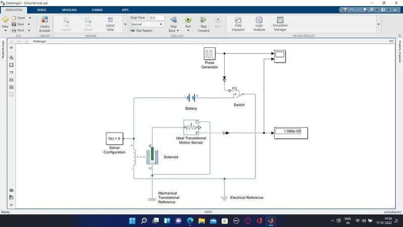
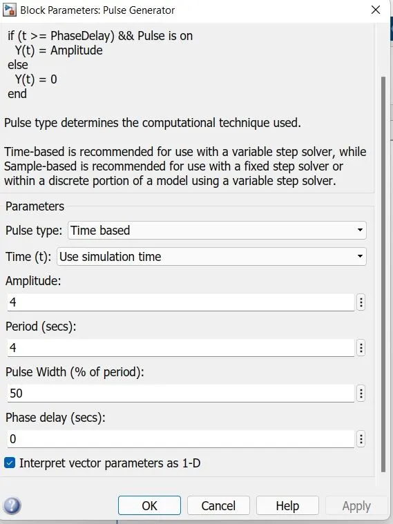
we have to create a situation where switch is closed for two seconds and then released , the input pulse block parameter has to set accordingly to achieve 2 seconds to ring ,the time period has to set to 4 seconds with a pulse width of 50% and its amplitude is set as 4.
Pulse Generator -Block Parameters
The pulse generator /input signal is fed through a convertor simulink to PS convertor and which is in turn connected to an electrical circuit. The one end of the switch is connected to positive terminal of battery and the other terminal is connected to negative terminal of solenoid . The positve terminal of solenoid is connected to negative terminal of the battery.
Electrical reference and solver configration are also added to the circuit.
Coming to Mechanical Connection of solenoid , The port C of solenoid and Ideal translational motion sensor is connected to mecanical reference and port R is connected to Ideal Translational Motion Sensor. The Port P of Ideal translational Motion sensor is connected to PS(Physical Signal) to Simulink Convertor which in turn connected to Scope and Display.
Input & Output Signal Observed Under Scope:
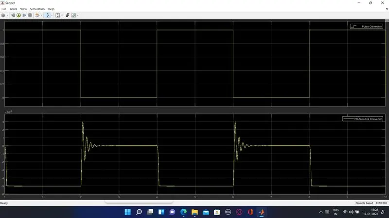
Result:
The above plot shows the Input signal from pulse Genarator and Output signal from PS to Simulink Converter
The vibration indicates that the bell is ringing at the interval of 2 seconds with a delay of 2 seconds.
Question 2:-
Use A Thermistor to Sense the temperature of a heater and turn ON or turn OFF the Fan:-
Thermistor
A Thermistor is a semiconductor which has a higher resistance than that of a conductor and lower than that of insulator. Its Electrical resistance varies with the change in temperature or it can be stated as thermally sensitive resistor.
There are two types of thermistors namely
1.Negative Temperature Coefficient Thermistor (NTC)
This type of Thermistor will decrease its resistance value when temperature increases.
2.Positive Temperature Coefficient Thermistor (PTC)
This type of thermistor will increase its resistance with respect to increase in temperature.
Thermistor's relation with temperature is based on the material on which they are made.
NTC Thermistor's are used in temperature measurements and control
PTC Thermistor's are used in circuit protection (Fuses) and current limiting resistors.
Model Diagram
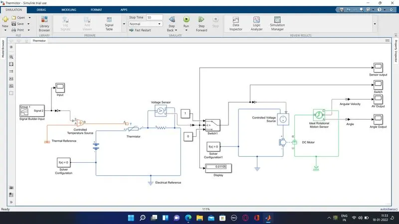
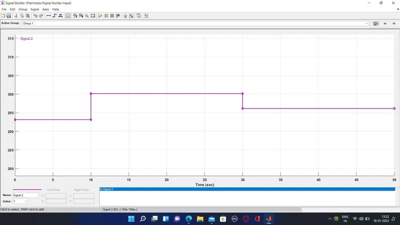
The Block Diagram represent the use of thermistor to sense the temperature of a heater and turn ON or turn OFF the fan as per the condition , where temperature is 20 C from 0 to 10 seconds, 27 C from 10 to 30 seconds, 23 C from 30 to 50 seconds where the fan should be ON if the temperature above 25 C and below 25 C the fan should be turn OFF
To generate the temperature conditions a signal builder is used with controlled temperature source through simulink to PS Convertor ,the simulink to ps converter parameter filter need to be applied. The Simulink signal which varies with time is generated using a signal builder which is represented below
The Controlled Voltage Source is connected to the thermistor which is used in sensing the temperature of the heater and positive and negative side are connected to postive terminal of battery and to a resistor parallel to voltage sensor respectively.
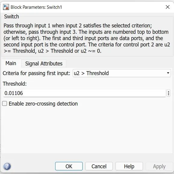
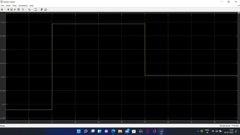
The switch is connected inorder to satisfy the condition for turning ON and OFF of fan there by providing a threshold value as 0.01106 which is obtained from the voltage sensor graph or numerically can be obtained through display block connected across the voltage sensor block, The parameter of switch block is given as follows
The output of switch is connected across a DC Motor Circuit through a controlled voltage source along with Electrical reference and the output from DC motor is connected to Rotational Motion sensor along with rotational reference and the sensor output Angular velocity and angle is observed through scope with the help of PS to simulink converter.
Result:
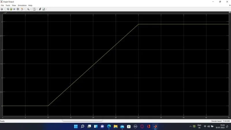
The Output Graph represent the fan is ON when the temperature is greater than 25 C(298.15 K)which is between the time period 10 to 30 seconds and OFF when temperature is below 25 C which can be obseved through DC Motor Operation by using Rotational Motion sensor output
Voltage Sensor Output
Angular Velocity Output
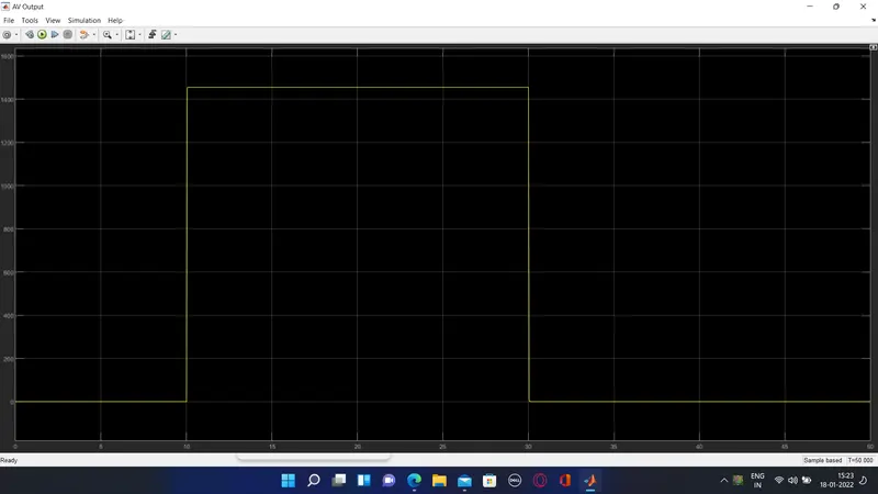
From the above result it is observed that the angular velocity during the period of 10 to 30 seconds at which the temperature is above 25 C(298.15 K) and the change in angle is observed is as below
File Reference
The Simulink file is attached below for your kind references
Attached Reference file as follows
Question 1: Doorbell - File Name :- Challege2.slx
Question 2: Thermistor - File Name :- Thermistor.slx