Week - 4
1) Control Logic of Washing Machine using Stateflow:
To implement the control logic of washing machine using stateflow as per given sequence
a) If the power supply is available the system starts working.
b) If water supply is not available , stop the process and indicate through LED.
c) Soaking time should be 200 sec followed by wasing time of 100 sec.
d) Then rinsing happens for next 20 sec and dryer runs for 50 sec.
After all this process have completed then turn on the finish LED.
The Block diagram of the above mentioned model is found below
Block Diagram:
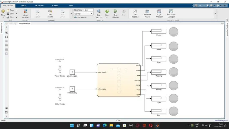
Chart - Block Diagram
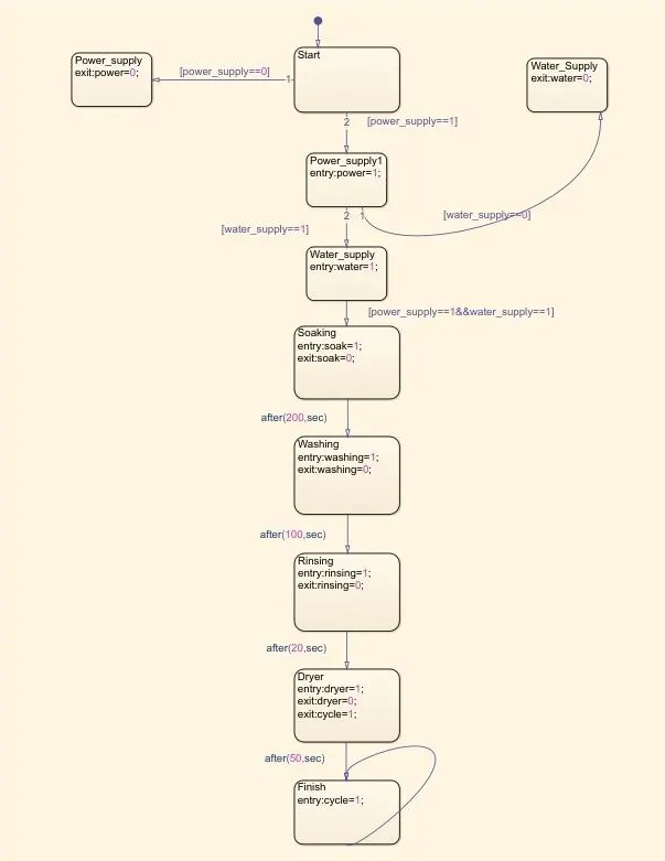
As per the stateflow the Washing Machine will start only when power_supply is at ON Condition and water_supply should also be at ON condition or else it will exit.
Further after power supply and water Supply is available then further process takes place, that is Soaking which will take place for a period of 200 sec since there is delay given before next operation
Only after 200 sec washing takes place and after 100 sec of delay time rinsing and after 20 sec of rinsing dryer operation takes place for 50 sec and after complition of the process the Finish LED glows.
Parmeters:
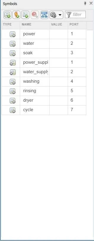
power_supply & water_supply are provided as Input for the chart,
Power,Water,Soak,Washing,Rinsing,Dryer and Cycle are provided as Output of the chart.
The Simulation is run for a period of 450 sec so as they can complete an Entire Cycle of the operation
Output:
The Output is Run for 450 sec so as to understand the entire operation taking place during the cycle
The Power Supply is ON and Water Supply is at OFF condition
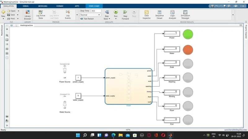
Whereas in above case water supply is not available so the water LED glows RED
When Both Power and Water Supply is at ON Condition:
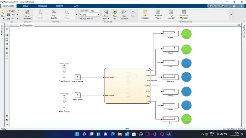
The Power and water supply which is available is indicated by Green LED
The process complition is highlighted using Blue LED
After Complition of Entire process the Green LED glows at End display.
Hence the implementation of Control logic of a washing machine using stateflow with the all above mentioned sequence is there by achived.
2) Gear Shift Logic:
The Gear Shift logic are made using the below given conditions and Colour code added for reference to visvalize the gear change
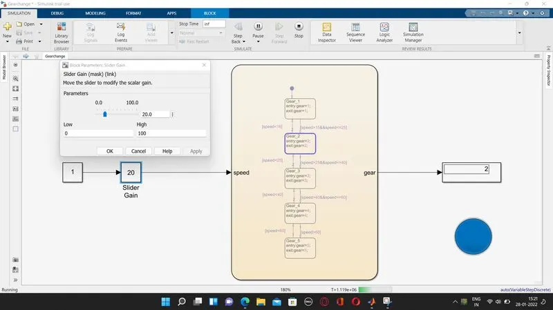
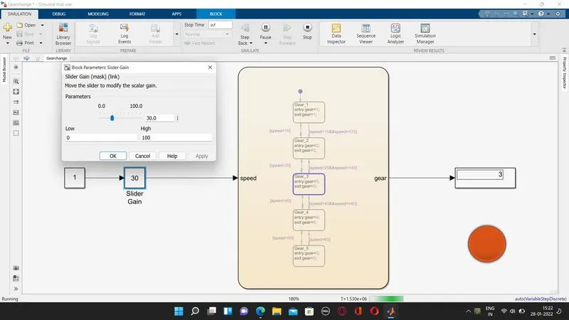
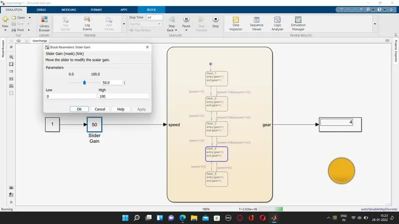
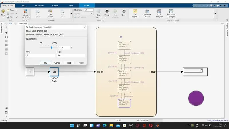
SPEED RANGE GEAR Colour
0 TO 15 1 Green
16 TO 25 2 Blue
26 TO 40 3 Red
41 TO 60 4 Yellow
Above 60 5 Purple
And the Input should be given while running the sumulation
The model Diagram for above mentioned gear shift logic is as below
Block Diagram
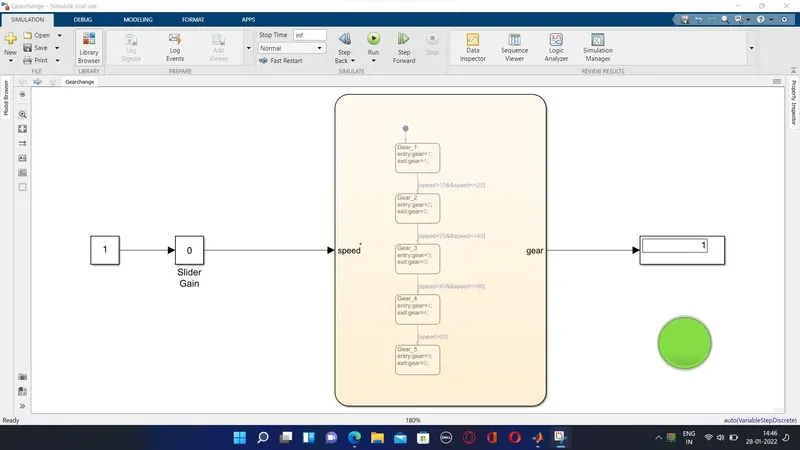
In the Block Diagram ,a slider gain is used inorder to change the input during the run time and the chart block containing the logic behind the gear shift and the display represents the current gear and the LED connected below represents the gear change by highlighting the respective colour for the gear.
The Slider Gain Value is Set to 0 to 100 and the run time is given as 'Inf' so that tha simulation will run until we stop it.
Chart Block & Parameter Block:
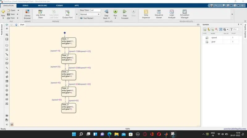
In above Chart the logics are provided as per the condition provided above
The Speed is provided as input to the chart through Slider Gain
The Output of the chart is Gear which is connected through Display and in turn connected to an LED.
Output:
The Output at Speed of 10 kmph , Gear 1(Green)
By setting the value of slider gain at 10 we get the following output
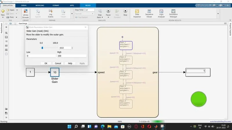
The Output at Speed of 20 kmph , Gear 2(Blue)
The Output at Speed of 30 kmph , Gear 3(Red)
The Output at Speed of 50 kmph , Gear 4(Yellow)
The Output at Speed of 70 kmph , Gear 5(Purple)
Thus the Stateflow for Gear Shifting as per above mentioned condition using simulink is achived.
The Model for Washing Machine and Gear Shift by using statefow is attached