Week 7 State of charge estimation
Simulation of Closed-loop BMS
The BMS model consists of a BMS ECU (electrical control unit) and a plant. The control unit with itsvarious monitoring and control algorithms is connected to a block with the representation of the battery pack and associated circuitry and peripherals
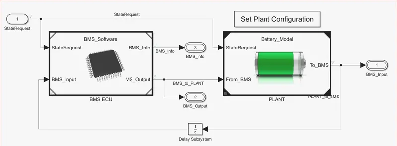
State Machine in the BMS ECU defines the main operating state of the BMS The state machine has four parallel states (parallel meaning that they can be active at the same time):
The first one defines the variable BMS State vwhich indicates standby, driving, charging, and fault. Charging comprises constant Current and constant voltage stages. The second state switches the fault state ON in case a current, voltage, or temperature vatue reaches an unsafe leve The third and fourth states define the contactor ON and OFF switchingsequence for the charger and inverter This is needed to avoid an excessively large current inrush at the beginning of the charging stage
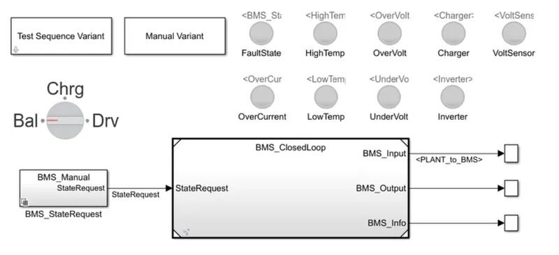
The haness dashboard is used to control and identify the test case states in the state machine. It consists of the test sequence variant subsystem which holds three different test cases. This dashboard also helps in determining the fault states and other parameters as shown in the diagram below The green color indicates that the system is working without any erors while the red signal will indicate that there is a fault in the system.
CASE 1:DRIVE-BALANCE-CHARGE-BALANCE ,THERE ARE NO ERROR AND FAULT

When the simulation begins,initially the vehicle is in a driving state and the SOC will decrease for this time period After a time period 3000seconds, the next stepis balancing mode and the vehicle is in standby condition. After another 1000 seconds, the vehice is in the charging phase and the battery's SOC increases almost to 100%. The next phase is the post charging phase in which the vehicie again goes for the standby mode
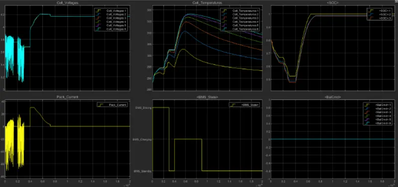
The input cycle can be seen in the BMS_State plot in which the vehicle initially' undergoes driving, then charging till SOC=90% and then later in the standby state. During Charging the Battery pack voltage is increased up to 4.2V. The cell temperatureincreases during the driving and charging cycle and starts fallirng off in standby mode. The SOC drops to less than 50% after the driving cycle and then later put into charging until SOC Reaches 100%. The current supplied to the EV during the driving phase can be seen in the current plot.
CASE-2:Drive-charge,High-temperaturefault

After 10000 sec the drive cycle is over , fault condition occure and so the SOC deos not increase even for charging phase
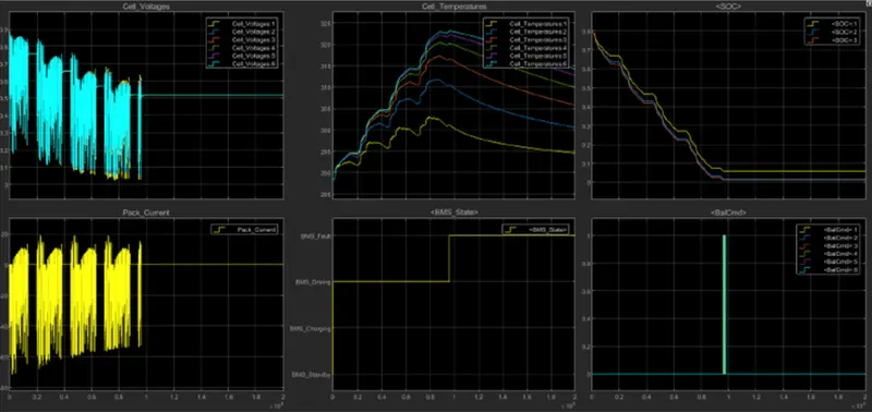
cell temperature increases during driving,and since it is higher than recommended, BMS stops the battery from charging, so we can a gradual decrease in temperature
CASE-3:charging, there is no fault

the SOC increase from 80% to 100% and then remain in standby mode
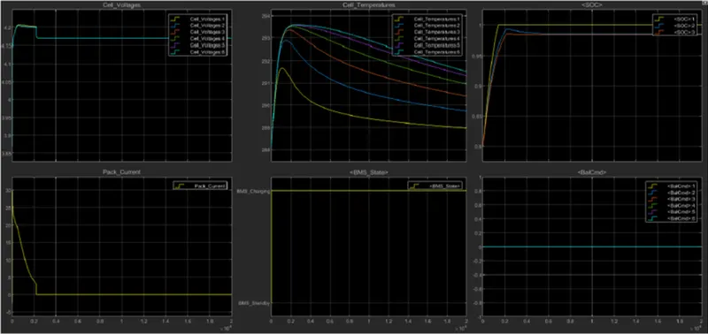
During charging SOC increase from 80% to 100%, temperature increase during charging and decrese in the standby state of the BMS
What is coulomb counting? How BMS implements coulomb counting for SOC estimation?
Definition and Classification of SOC Estimation
The SOC is one of the most important pararneters for batteries, but its definition presents many differentissues In general, the SOC of a battery is defined as the ratio of its current capacity to the nominal capacity . The nominal capacity is given by the manufacturer and represents the maximum amount of charge that can be stored in the battery. The SOC can be defined as follows:
The various mathematical methods of estimation are clasified according to methodology. The classification of these SOC estimation methods is different in the varicus iteratures. However, some literatures allow a division into the following four categories.
Direct measurement: this method uses physical battery properties, such as the voltage and impedance of the battery.
Book-keeping estimation: this method uses discharging current as the input and integrates the discharging current over time to calculate the SOC
Adaptive systems: the adaptive systems are self designing and can automatically adjust the SOC for different discharging conditions. Various new adaptive systems for SOC estimation have been developed
Hybridmethods: the hybrid models benefit from the advantages of each SOC estimation method and allow a globallyoptimal estimation performance. The literature shows that the hybrid methods generally produce goodestimation of SOC. compared to individual methods.
The applications of spec1fic SOC estimation methods in battery management system (BMS) are consequentially different.
Overview of SOC estimating mathematical methods
Direct measurement
Direct measurement methods refer to some physical batteryproperties such as the terminal voltage and impedance. Many different direct methods have been employed: open circuit voltage method, terminal voltage method, impedance measurerment mnethod, and impedance spectroscopy method.
Open circuit method
There is approximately a linear relationship between the SOC of the lead-acid battery and its open circuit voltage (OCV given by Voclt) = a SOC(t) +a where is the SOCt) of the battery at t.a, is the battery terminal voltage when SOC- 0%. and a is obtained from knowing the value of a and V() at SOC-100%. By the estimation of the SOC is equivalent to the estimation of its OCv. The OCV method based on the OCV batteries is proportional to the SOC when they are disconnected from the loads for a period longer than two hours. However, such a long disconnection time may be too long to be implemented for battery Unlike the lead-acid battery, the Li-ion battery does not have a linear relationship between the OCV and SOC.A typical relationship of EL ion battery between SOC and OCV is shown in Figure The OCV relationship with SOC was determined from applying a pulse load on the L-ion battery, then allowing the battery to reach equilibrium.
Typical relationship between SOC and OcV
The relationship between the OCV and SOC cannot be exactly the same for all batteries, Because the conventional OCV-SOC differs among batteries, there is a problem in that the relationship of the OCV-SOC should be measured to estimateaccurately the SOC.The SOC and the capacity of a lithium-ion battery are estimated using the dual extended Kalman filter with the proposed method
Teminal voltage method
The terminal voltage method is based on the terminal voltage drops because of the internal impedances when the battery is discharging, so the electromotive force (EMF) of battery is proportional to the terminal voltage. Since the EMF of battery is approxirmately linear proportional to the SOC, the terminal voltage of battery is also approximately linear proportional to the SOC. The terminal voltage method has been employed at different discharge currents and temperatures But at the end of battery discharge, the estimated error of termina voltage method is large, because the terminal voltage of batterysuddenly drops at the end of discharge.
Impendance method
Amongthe techniques which have been employed, impedance measurements provide knowledge of several parameters, the magnitudes of which may depend on the SOCof the battery. Although the impedance parameters and their variations with SOC are not unique for alt battery systems, it appears to be imperative to perform a wide range of impedance experiments for identification and use of impedance parameters for estimating the SOC of a given battery
Impendance Spectroscopy method
The impedance spectroscopy method measures battery impedances over a wide range of ac frequencies at different charge and discharge currents. The values of the model impedances are found by least-squares fitting to measured impedance values. SOC may be indirectly inferred by measuring present battery impedances and correlating them with knownimpedances at various SOC levels Coulomb counting method The Coulomb counting method measures the discharging current of a battery and integrates the discharging current over time in orcier to estimate SOc.
Coulomb counting method
is done to estimate the SOC(t), which is estimated from the discharging current Kt and previously estimated SOC values, SOC(t-1).SOCis calculated by the following equation SOCt)=SOc(t 1) () But there are several factors that affectthe accuracy of Coulomb counting method includins. temperature. battery history. discharge ctirrent and cycde life