Week 7 State of charge estimation
1.Simulate the 3 test cases from harness dashboard and write a detailed report on the results -
Lithium-ion battery packs are the widely used energy storage systems in electric vehicles.
The battery management system (BMS) is responsible for safe operation, performance, and battery life under diverse charge-discharge and environmental conditions. When designing a BMS the cell voltage and temperature, state of charge, state of health and the charging profile has to be controlled and maintained.
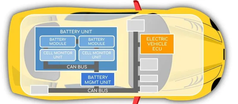
- The Battery Management System (BMS) manages stored power in an on-board high voltage (HV) battery and delivers power to the rest of the vehicle. Main functions include cell balancing, cell health and wear leveling, charge and discharge monitoring and safety assurance. All of these functions require galvanic isolation to separate lower voltage systems from high voltage domains.
- EVs utilize Battery Management Systems for the main battery-based power supply, and HEVs use BMS for battery-side portion of power, complimentary to the internal combustion engine (ICE). BMS monitors the voltage, current, temperature, and wear leveling of battery cells. Additional functions include monitoring faults, system health, available energy and remaining useful lifetime. Individual lithium-ion battery cells are in the 3 – 4V range. They are connected in series to deliver higher voltage, and in parallel to increase capacity.
- To monitor the modules and cells, the Battery Management Sysytem may have a centralized architecture, or a distributed/modular architecture consisting of a BMS master and several remote BMS units. In distributed BMS systems, remote units monitoring individual cells may be connected in parallel to the BMS master, or they may be daisy-chained in series. In any case, connections from the battery modules or BMS remote units to the BMS master must be isolated to protect the BMS master from the battery voltages.
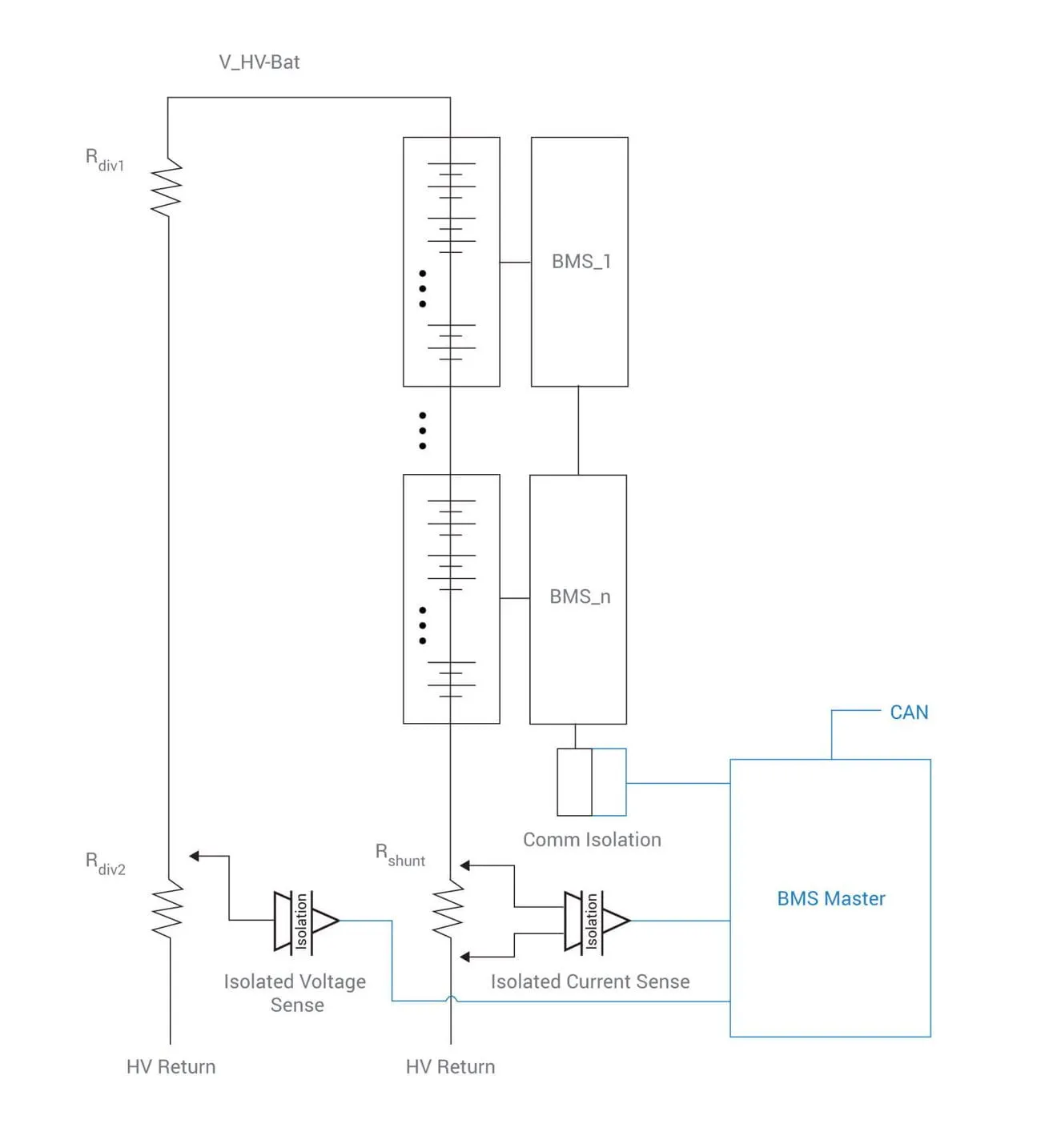
- The diagram below depicts a distributed Battery Management System with multiple packs of cells, each with a remote BMS control unit.
- In this configuration, measurements on cells within the battery modules are made by the remote BMS units and reported over a series connection to the BMS Master controller. Current measurement for the full stack is made using a shunt resistor at the bottom of the stack and an isolated current amp, such as Si892x.
- The BMS controller can calculate the voltage of the full stack by summing the voltages of the modules, but a redundant safety-check isolated voltage measurement of the full stack can be made using a resistor divider and isolated voltage sense amp.
- The entire system can be monitored and controlled via an automotive bus such as CAN which is isolated with digital isolators, including Si86xx and digital isolators with integrated dc-dc power converters such as Si86xx.
Now we will perform the simulation of BMS model in simulink along with the test cases -
- Firstly we need to download the given file and extract it.
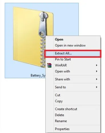
- After extracting go to -MATLAB - simuink model and open Battery system file
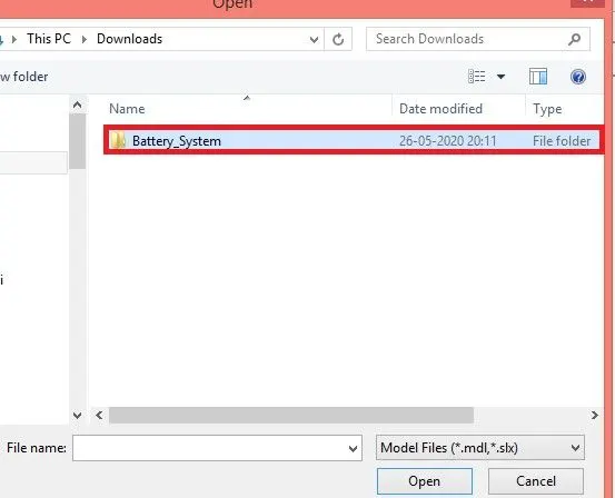
- After clicking on Battery_System go to plant -
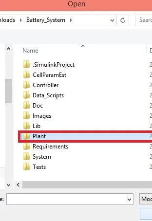
And click on the battery model -
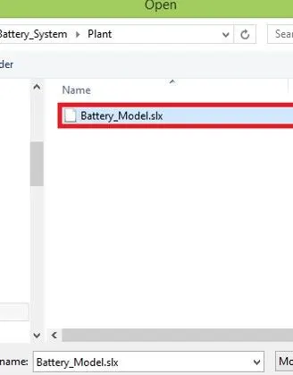
- Now after clicking on the battery model , click on open project and model.
- Now the documentation opens up and click on BMS system in the MATLAB toolstrip and the following simulink model opens up.
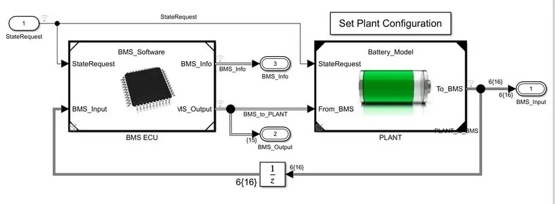
- Click on BMS ECU and the following model opens up
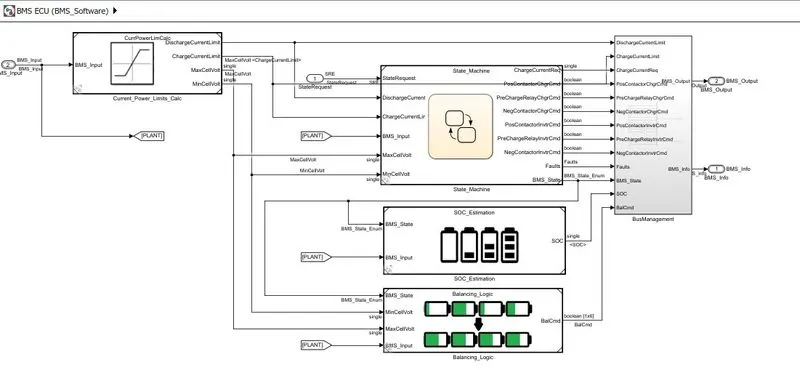
- It has state machine which defines the main operating state of BMS. The state machine has four parallel states.
- The first defines the variable BMS_State which indicates standby, driving, charging, and fault. Charging comprises constant current and constant voltage stages.
- The second state switches the fault state ON in case a current, voltage, or temperature value reaches an unsafe level.
- The third and fourth states define the contactor ON and OFF switching sequence for the charger and inverter.
- This is needed to avoid an excessively large current inrush at the beginning of the charging stage.
- After opening the BMS system, we have to go for BMS harness dashboard. the following simulink model opens up -
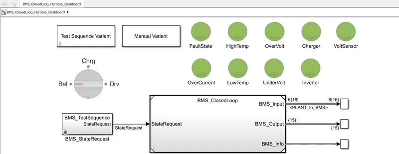
Now we will perform the three test cases for BMS_Closedloop_Harness_Dashboard
Test case 1 -
- Click on the Test Sequence Variant and choose test case 1 as shown below
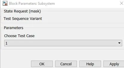
- Now we should go back to BMS system and run the simulation. This is done due to avoiding the errors in the system and the following scope plot appears.
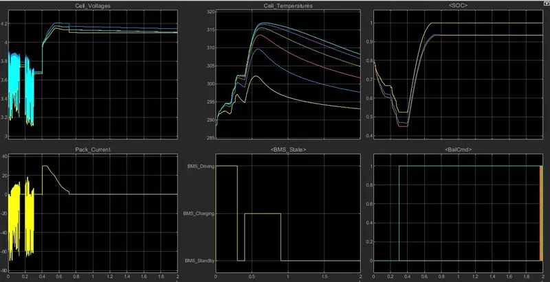
Now to check the faults we run the harness dashboard system and the dashboard shows that there are no errors as below -
From the scope we can conclude that-
- The input cycle can be seen in the BMS_State plot in which the vehicle initially undergoes driving, then charging till SOC= 90% and then later in standby state.
- During Charging the Battery pack voltage is increased upto 4.2V.
- The cell temperature increases during the driving and charging cycle and starts falling off in standby mode.
- The SOC drops to less than 50% after the driving cycle and then later put into charging until SOC Reaches 100%.
- The Current supplied to the EV during driving phase can be seen in the current plot.
Test case 2 -
- Click on the Test Sequence Variant and choose test case 2 as shown below -
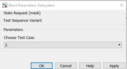
Now we will again run the simulation and the following dashboard shows the output -
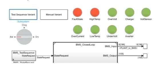
- It shows that it has errors since the red colour light shows error in the BMS system.
- The following plot appears as shown below -
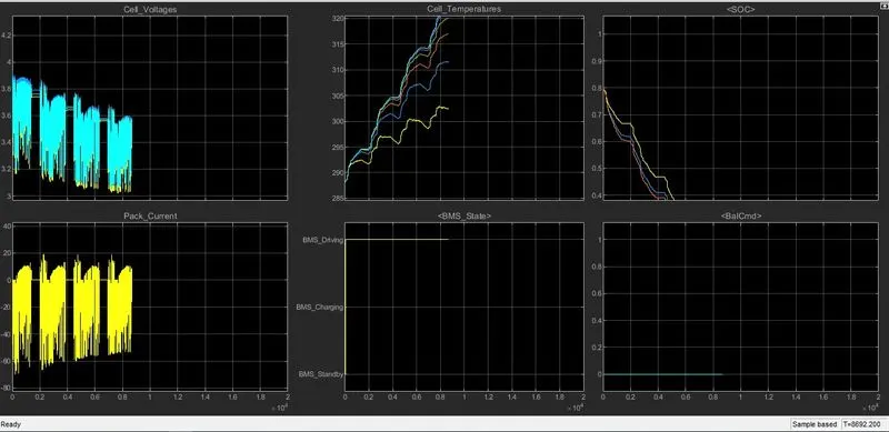
- After a sometime the simulation stops due the error occured in the BMS system.
- After 10,000 sec when the driving cycle is over, the fault condition occurs and so the SOC does not increase even for the charging phase.
Test case 3 -
- Click on the Test Sequence Variant and choose test case 3 as shown below-
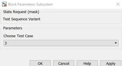
- After applying the third test case we again run the simulation.
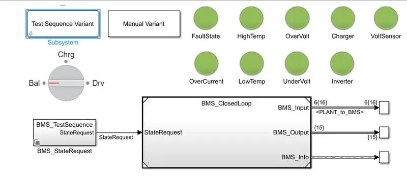
- The above dashboard appears and all the green lights are lighted shows that the BMS system has no errors.
- The following plot appears -
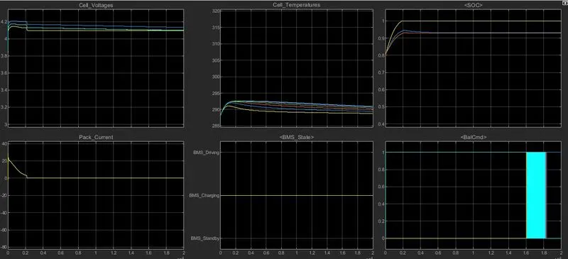
- This above plot shows that SOC increases from 80% to 100% and then remains in standby mode.
This is how all the test cases are performed and all the results are attached.
Conclusion -
All the test cases are conducted and the desired outputs are observed. And all the supporting images are attached and all the ouput plots are attached.
2.What is coulomb counting? Refer to the above model and explain how BMS implements coulomb counting for SOC estimation ?
Coulomb counting is a technique used to track the State of Charge of a battery pack. It works by integrating the active flowing current (measured in amps) over time to derive the total sum of energy entering or leaving the battery pack. This produces a capacity that is typically measured in Amp - hours.
- The Coulomb counting method is one of the most general and simple methods of estimating the SOC.
- We use it for a baseline comparison for more advanced methods. The Coulomb counting method measures the current of the battery and integrates the current over time to estimate SOC.
- Limitations of the method, which lead to other projects along these lines, include the fact that inaccurate current measurements accumulate to large errors, whereas accurate current measurement is expensive. Other factors such as temperature, battery history, initial SOC and cycle life also influence the precision of the SOC estimate.
- Practically speaking, some phenomena, such as decreasing SOC when the battery is resting, and variations with temperature changes, cannot be captured by the Coulomb counting method.
Steps to BMS implements coulomb counting for SOC estimation -
- Double click on the plant subsystem diagram -
Now the following system opens up -
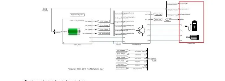
Now right click on the charger block and select library link and then select to library block from there and the following libraries links will be appeared.
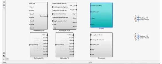
Clicking on the charge subsystem another circuit opens up as shown -
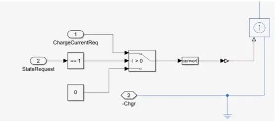 s
s
Similarly going back to load circuit, we can select library link and open all the libraries linked with the load subsystem. The following window opens up and shows the other libraries linked with the load.
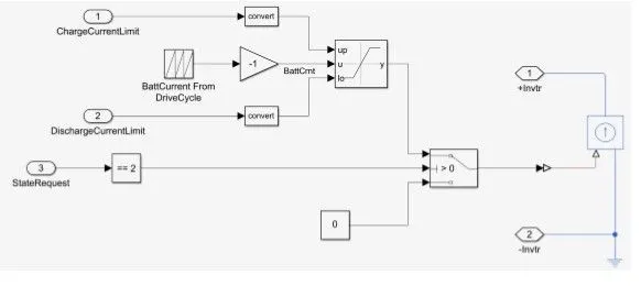
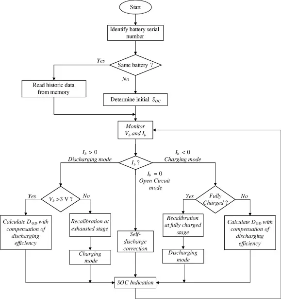
The Coulomb counting method measures the discharging current of a battery and integrates the discharging current over time in order to estimate SOC . Coulomb counting method is done to estimate the SOC(t), which is estimated from the discharging current, I(t) , and previously estimated SOC values, SOC(t-1) . SOC is calculated by the following equation:
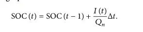
- But there are several factors that affect the accuracy of Coulomb counting method including temperature, battery history, discharge current, and cycle life.
- To improve the Coulomb counting method, a new technique called modified Coulomb counting method is proposed. The modified Coulomb counting method uses the corrected current to improve the accuracy of estimation.
- The corrected current is the function of discharging current. There is a quadratic relationship between the corrected current and discharging current of battery. By practice of experimental data, corrected current is calculated by the following form:

where, k1, k2 and k0 are constant values obtained from the practice experimental data.
In modified Coulomb counting method, SOC is calculated by the following equation -

The following flow chart shows about coulomb counting -