Project 1 Mechanical design of battery pack
Mechanical Design of Battery pack
Aim - To build a Battery pack of capacity 18kWh for a cell model - ANR26650M1-B
Now we are going to design the required battery pack model along with its disclosure.
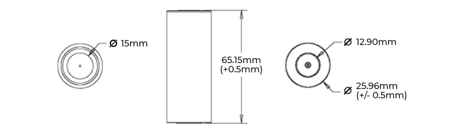
Here we took the A123 systems cell model - ANR26650M1-B in the above image.
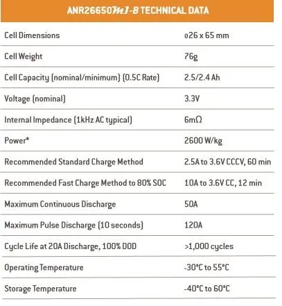
Cell Specifications of Model - ANR26650M1-B -
https://drive.google.com/file/d/18FwoLzGB86MN8MNjW8wgxy5M0XcKYOXO/view?usp=sharing
- A123’s high-performance Nanophosphate lithium iron phosphate (LiFePO4) battery technology delivers high power and energy density combined with excellent safety performance and extensive life cycling in a lighter weight, more compact package.
- Their cells have low capacity loss and impedance growth over time as well as high usable energy over a wide state of charge (SOC) range, allowing our systems to meet end-of-life power and energy requirements with minimal pack oversizing.
Applications -
Commercial Applications -
- Datacenter.
- UPSTelecom backup
- IT backup.
- Autonomously guided vehicles (AGVs).
- Industrial robotics and material handling equipment.
Government Applications -
- Military vehicles.
- Military power grids.
- Soldier power.
- Directed energy.
Grid Applications -
- Frequency regulation.
- Renewables integration.
- Reserve capacity.
- Transmission and distribution.
Transportation Solutions -
Hybrid, plug-in hybrid and electric vehicle battery systems for:
- Commercial vehicles.
- Off-highway vehicles.
- Passenger vehicles
In this cell chemistry type we are using LiFePO4 (Lithium iron phosphate). Now we will understand the detail structure and functionality of the battery.
LFP batteries stands for Lithium iron phosphate(LiFePO4) batteries, which is known as li-phosphate batteries as well. They use phosphate as cathode material. In addition, they benefit from the low resistance properties that enhance their thermal stability and safety.
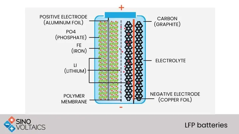
LFP batteries and technologies -
- LFP (Lithium iron phosphate) was invented in the year 1996.
- Its anode material is LiaC6, the cathode material is LibFePO4 and the carrier is Li+.
- They use LFP batteries in different applications like electric cars, electric buses and electric trucks.
- The LFP is ideal for use in electric trucks or buses – as volume or weight isn’t really a restriction as is in cars- because the battery is less energy dense yet cheaper to manufacture than other Li-ion batteries types.
- In addition, they use LFP batteries in other applications like electric motorcycles which need a longer life cycle and increased safety.
- LFP provides good electrochemical performance with lower resistance. This is enabled by the nano scale phosphate cathode material. The main benefits are long cycle life, higher current rating and thermal stability which means extra safety.
Currently, LiFePO4 is one of the most successfully commercialized cathode materials in the rechargable lithium ion battery system, owing to its excellent safety performance and remarkable electrochemical properties. and it will get good market in the future. Although it is widely used or recognized that the crystalline structure of a cathode material largely dectates the electrochemical properties ( like capacity, cycle life and rate capabilities), this instrinsic connection in LiFePO4 has not been systematically reviewed.
Different from the previous reviews, which mainly focus on the improvement of electrochemical performance by all kinds of techniques, the relationship between its electrochemical performance and bulk surface is reviewed and discussed.
Firstly, it is revealed that the intra - particle Li+ transfer is influenced by several properties of the bulk, including crystalline structures, defects and electronic structured. Secondly, it is demonstrated that the surface/ Interfacial structures of LiFePO4, which can be reconstructed artificially or spontaneously. also have great impacts on the performances. Lastly, the instrinsic connection between the structure and performance is preliminalry established, showing new perspectives on the strategy for further improvement and contributing to a comprehensive understanding of LIFePO4.
Lithium Nano Phosphate -
It is a registered trademark for a lithium ion phosphate battery technology that maximises the performance of the standard technology.
Safety -
- One important advantage over other lithium-ion chemistries is thermal and chemical stability, which improves battery safety. LiFePO
4 is an intrinsically safer cathode material than LiCoO
2 and manganese dioxide spinels through omission of the cobalt with its negativetemperature coefficient of resistancethat can encourage thermal runaway. The P-O bond in the (PO
4)3−
ion is stronger than the Co-O bond in the (CoO
2)−
ion, so that when abused (short circuted, over heated etc.), the oxygen atoms are released more slowly. This stabilization of the redox energies also promotes faster ion migration. - As lithium migrates out of the cathode in a LiCoO
2 cell, the CoO
2 undergoes non linear expansion that affects the structural integrity of the cell. The fully lithiated and unlithiated states of LiFePO
4 are structurally similar which means that LiFePO
4 cells are more structurally stable than LiCoO
2 cells. - No lithium remains in the cathode of a fully charged LiFePO
4 cell. (In a LiCoO
2 cell, approximately 50% remains.) LiFePO
4 is highly resilient during oxygen loss, which typically results in an exothermic reaction in other lithium cells.As a result, LiFePO
4 cells are harder to ignite in the event of mishandling (especially during charge). - The LiFePO
4 battery does not decompose at high temperatures.
Power -
- High power products are able to pulse at discharge rates as high as 100C and deliver superior power by weight or volume in a a cost effective solution.
- With theirlow impedence and thermally conductive design, high power cells can be continuosly dischraged at a 35C rate, a marked improvement over the other rechargeable battery alternatives.
- And has consistent power over a wide state of charge (SOC) range.
Understanding the fundamental chemical differences betwen nanophosphate and other technologies is necessary to develop a complete and accurate assessment of the optimal advanced battery system that will deliver the best performance for a given application.
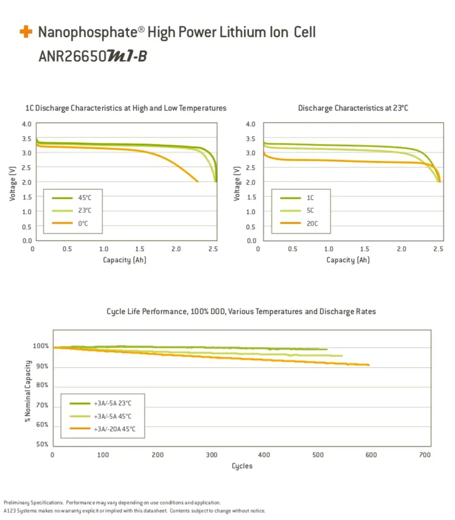
Discharge charactristics of LiFePO4 cell -
Advantages of LFP -
- Durability
- Long lifecycle
- Low cost
- Excellent safety
Disadvantages of LFP -
- More tolerant to conditions of full charge and is less stressed at higher voltage for a long time.
- lower nominal voltage which reduces the specific energy
- Higher self discharge than other types Li-ion batteries, which causes balancing issues with aging.
Designing of 18 kWh battery pack -
- These days, the electric vehicle market is gradually expanding. Consequently, the interest in lithium ion batteries, the power source EVs, is growing as well. However, we sometimes get confused with the different battery terminologies when reading EV related articles or reports. “Battery cell”, “battery module”, “battery pack”. Although “battery” is the most commonly used name, the aforementioned three words actually refer to different types of batteries.
- Today, we will look into the precise definitions of EV battery’s “cell”, “module” and “pack”.
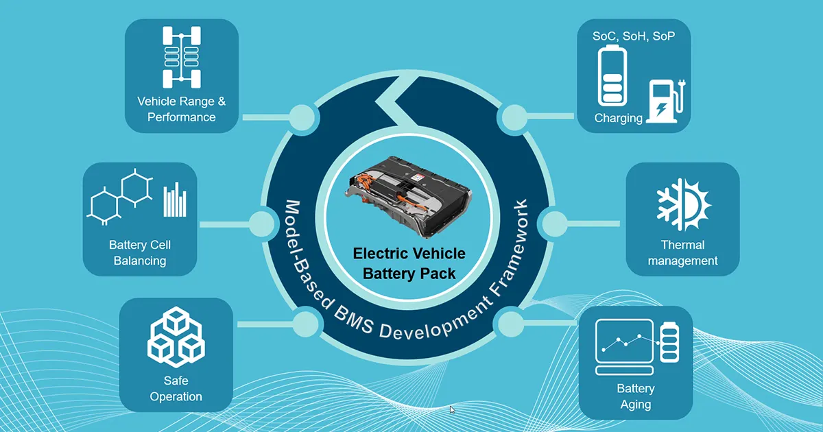
Electric Vehicle Battery is Composed of “Cell → Module → Pack”
- To operate an electric vehicle, an enormous amount of power thousand times stronger than that of a smart phone is required. That is why EVs need from dozens of battery cells up to as many as thousands. The composition of an EV battery might vary slightly depending on the types of electric vehicles, but generally EV batteries are composed of cells, modules and a pack.
- In fact, to safely and efficiently manage the countless battery cells mounted in one EV, the cells are installed in forms of modules and packs. Simply put, cells, modules and packs are units of gathered batteries. A cluster of cells make up a module and a cluster of modules make up a pack. Ultimately, in an electric vehicle, one form of battery is installed: a pack.
Battery Pack Design -
The purpose of a battery pack is to provide a convenient integrated power source for portable applications. The advantages of using custom designs are outlined in the section on Benefits of custom packs. The pack may fulfil several functions:-
- It enables higher voltage or higher capacity batteries to be built up from low voltage, low capacity cells.
- It houses a cell or a bank of cells together with the associated interconnections in a single convenient pack.
- It accommodates any necessary monitoring and electronic protection devices or circuits within the pack.
- It can accommodate additional circuitry such as indicator lights, heaters, cooling ducts and solar panels.
- It matches and meshes with the cavity in the product which the battery is intended to power providing both electrical and mechanical interfaces.
- It can provide unique electrical and mechanical interfaces to ensure compatibility both of the battery with the intended product and the charger with the battery.
Capacity and Voltage -
- With a simple series chain of cells, the battery capacity in AmpHours is the same as the capacity of the individual cells since the current flows equally through all the cells in the chain.
- High battery voltages are achieved by adding more cells in a series chain. The voltage of the battery is the voltage of a single cell multiplied by the number of cells in the chain. This does not increase the AmpHour capacity of the battery , but it increases the WattHour capacity, or the total stored energy, in proportion to the number of cells in the chain.
- Battery capacity can increased through adding more parallel cells. This increases the AmpHour capacity as well as the WattHour capacity without increasing the battery voltage. For batteries with parallel chains the capacity of the battery is the capacity of the individual chain multiplied by the number of parallel chains.
- Whereas cell voltage is fixed by the cell chemistry, cell capacity depends on the surface area of the electrodes and the volume of the electrolyte, - that is, the physical size of the cell. If at all possible the number of cells in a pack should be minimised to simplify the design and to minimise potential reliability problems. Fewer cells require fewer support electronics. Thus parallel chains should be avoided by specifying the highest capacity cells available. Design issues for multi-cell batteries are considered further in the section on cell balancing.
Note - Cells with different capacities or cell chemistries should not be mixed in a single battery pack.
Pack design options -
- The design of the outer package or housing of the battery depends to a great extent on the components it has to accommodate and the physical protection it has to provide for them. These components are not just the cells, but also protection devices, electronic circuits, interconnections and connectors which must all be specified before the final battery case can be designed. For high power, high energy batteries robust packaging is required for safety reasons.
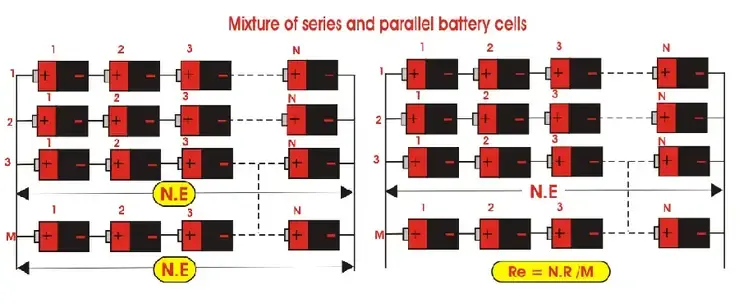
Cell configuration -
- The ultimate shape and dimensions of the battery pack are mostly governed by the cavity which is planned to house it within the intended application. This in turn dictates the possible cell sizes and layouts which can be used.
- Prismatic cells provide the best space utilisation, however cylindrical cells provide simpler cooling options for high power batteries. The use of pouch cells provides the product designer more freedom in specifying the shape of the battery cavity permitting very compact designs.
- The orientation of the cells is designed to minimise the interconnections between the cells.
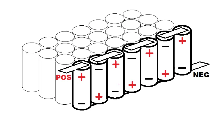
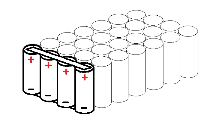
Battery Electronics -
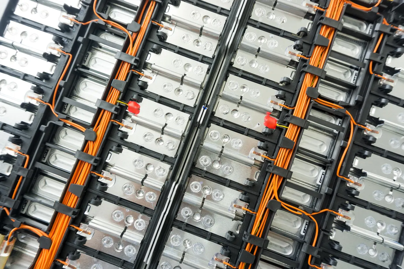
- Besides the cells many battery packs now incorporate associated electronic circuits. These may be protection devices and circuits, monitoring circuits, charge controllers, fuel gauges, and indicator lights. Electronics for high power multi-cell packs also include cell balancing and communications functions.
- The packs may also be designed to deliver more than one voltage from the basic cell combination, although applications requiring multiple voltage sources are more likely to make provision for this within the application.
- In addition to the basic battery support electronics the battery pack may include other functions such as heaters to extend the lower working temperature or solar cells to keep the battery fully charged. These circuits in turn have their own control circuits.
- Space, fixing points and methods and interconnections need to be allocated for all these electronic circuits.
Software -
- Sofware is a major component of Lithium batteries, particularly for automotive applications.
- Control systems are required to keep the cells within their specified operating range and to protect them from abuse. Fuel gauging needs complex algorithms to estimate the state of charge (SOC). Communications with other vehicle systems are needed for monitoring the battery status and controlling energy flows.
Internal Interconnections -
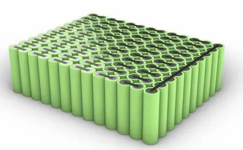
- Low power cells are usually connected together using nickel strips which are welded to the cell terminals or the case. Soldering is not recommended since the soldering process is apt to apply large, uncontrolled amounts of heat to the battery components which may damage the separators or the vents which are normally made of plastic.
- Modern computer controlled resistance welders allow much more precise control of the welding process, both limiting the amount of heat applied to the battery and localising the heat to a small desired area. Welding also provides a stronger, low resistance joint. The interconnecting strips often have complex shapes and profiles which may be stamped out of flat strip in a progressive die.
- High power cells may use solid copper bus bars or braided straps.
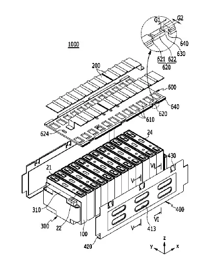
- The electronic components are usually mounted on a conventional printed circuit board (PCB).
- Flexible PCBs may cost more than rigid PCBs but they can be used to reduce the overall product costs. Not only do they save weight and space but they also provide more packaging options and they simplify physical interconnections and assembly operations as well as eliminating the need for connectors.
- Connectors may in fact be specified to facilitate assembly and disassembly if the design requires that individual battery components need to be changed or serviced but there is usually a cost and reliability penalty associated with such designs.
External Connections -
- The type of terminals or connections to the external circuits depend on, the current to be carried, the frequency with which the battery may be connected and disconnected and the design of the design of the circuit to which the battery will be connected.
- For low power circuits, gold plated contacts are the terminals of choice for connectors which are subject to frequent insertions. Gold is hard wearing, it has low contact resistance and doesn't oxidise. Flying leads with spade terminals or snap on studs are also used for low power applications. Metal tabs are also used on pouch cells.
- Terminals for high power applications are usually threaded metal studs to ensure a reliable connection. Safety requirements on high voltage batteries may also dictate shrouded terminals to prevent accidental exposure of the operator to dangerous voltages or of the battery to short circuits. Keyed or terminals or connections are also advisable to prevent connection to incorrect chargers or loads.
Thermal Design-
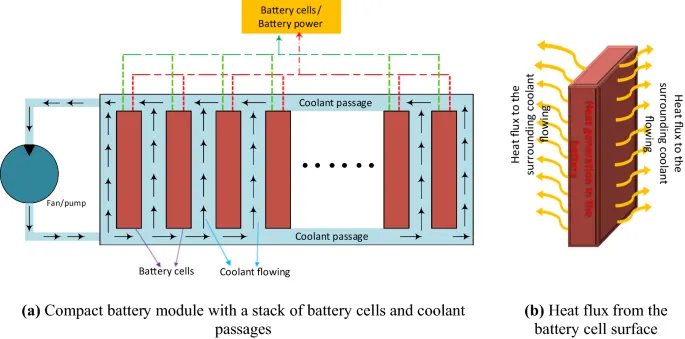
- Thermal management is a major issue in high power designs, particularly for automotive applications.
- As part of the battery system, it may be necessary to provide air or water cooling ducts, pumps or fans and heat exchangers for high temperature working or heaters for operating in low temperature environments. The layout of the cells should be conducive to managing heat flows within the pack.
Battery Packaging -
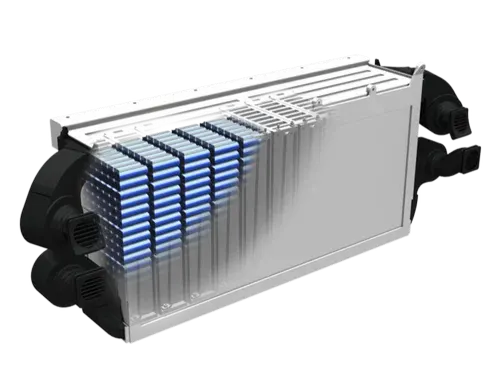
- The battery casing has to provide the mechanical and electrical interfaces to the product it is designed to power as well as to contain all the components outlined above.
- The simplest and least expensive packaging for small batteries is shrink wrap or vacuum formed plastic. These solutions are only possible if the battery is intended to be completely enclosed by the finished product.
- Injection moulded plastics are used to provide more precision packs. For enclosed packs designs using a minimum of materials are based around which a plastic frame holds the components in place thus minimising the cost, the weight and the size of the pack.
- The overall product cost can be further reduced by using insert mouldings in which the interconnection strips and the terminals are moulded into the plastic parts to eliminate both materials and assembly costs. over mouldings may also be used to encapsulate and protect small components or sub-assemblies.
- In some designs the battery pack forms part of the outer case of the end product. The colours and textures of the plastic must match the plastics of the rest of the product even though they may come from a completely different supplier. These designs are usually required to incorporate a mechanical latch to hold the battery in place. Again this latch as well as the terminals must interface with plastic parts from a different supplier so high precision and tight tolerances are essential.
- Batteries for traction applications are usually very large and heavy and subject to large physical forces as well as vibrations so substantial fixings are required to hold the cells in place. This is particularly necessary for batteries made up from pouch cells which are vulnerable to physical damage. Automotive battery packs must also withstand abuse and possible accidental damage so metal casings will normally be specified. The metal pack casing also serves to confine any incendiary event resulting from the failure of a cell or cells within the battery and to provide a measure of protection for the user.
- At the same time the case must also protect the cells and the electronics from the harsh operating environments of temperature extremes, water ingress, humidity and vibration in which these batteries work.Usually the complete pack is replaced when the battery has reached the end of its useful life. In certain circumstances however, for instance when the pack incorporates a lot of electronic circuits, it may be desirable to design the pack such that the cells within the pack can be replaced.
Other Considerations-
- Thermal effects need to be taken into account and, tolerances must allow for potential swelling of the cells. Some Lithium pouch cells may swell as much as 10% or more over the lifetime of the cell. For this reason potting is not recommended.
- In low power designs groups of pouch cells may be shrink wrapped but for higher power applications plastic or metal frames may be used both to provide physical protection of the cells as well as to allow for swelling.
- The battery pack should not normally be airtight or sealed since many batteries release hydrogen or oxygen during operation which could cause bursting of the pack or an explosion if the gases are allowed to accumulate. Lithium cells do not emit gases under normal circumstances, but in the case of failure and thermal breakdown, inflammable gases may be vented by the cells. Some form of ventilation or purging should be provided to avoid these problems.
- Tolerances should also allow for the use of alternative cells from other manufacturers. While the cells may be "standard" sizes, there could still be differences between cells from different vendors.
- High power batteries may need special ventilation or channels between the cells to permit forced air or liquid cooling.
To design 18kWh battery pack assume the following assumptions -
- We assume that there are 42 cells are connected in series and 52 cells are connected in parallel.
- All these cells are ANR26650M1-B type.
From the given datasheet we consider these values -
- Cell dimensions = 26*65 mm
- Cell weight = 76 g
- Cell capacity (Nominal/ Minimum) = 2.5/2.4 Ah
- Nominal voltage = 3.3 V
- Power = 2600W/kg
- Radius (r) = 0.013 m
- height = 0.065 m
Cell Calculations -
- Cell volume = phi*r*h
= 3.14*0.013*0.065
Cell Volume = 2.653*10(^-3)
- Cell Energy = Cell voltage * Cell Capacity = 3.3*2.5
Cell Energy = 8.25 kW
- Cell Energy Density = Cell energy / Cell Volume
= 8.25/2.653*10(^-3)
Cell Energy Density = 3.11kWh/m^3
Battery Pack Calculations -
Number of cells in series = 42
Number of cells in parallel = 52 Total number of cells = 42s * 52p = 2184 cells.
1. Total battery pack voltage = Nominal voltage of a cell * number of cells in series
= 3.3 * 42s
Total battery pack voltage = 138.6 V
2. Total Battery pack capacity = Nominal Cell capacity * number of cells in parallel
= 2.5 * 52 p
Total Battery pack capacity = 130 Ah
3. Total Energy = (Total battery pack voltage ) * ( Total Battery pack capacity)
= 138.6 * 130
Total Energy = 18.018 kWh
Now we have designed a battery pack of 18kWh capacity model by considering required assumptions.
4. Battery Pack Volume = cell volume * total number of cells = 2.653*10(^-3) * 2184
Battery Pack Volume = 5.79 m3
5. Energy density = Battery pack energy / volume
= 18.018/5.79
Energy density = 3.109 kWh/m^3
6. Total weight of the battery pack = Total number of cells * each cell weight
= 2184 * 0.076
Total weight of the battery pack = 165.984 kg
Conclusion - The desired Battery pack capacity of 18 kWh has been designed with considering all the values given in the data sheet. And the desired results are obtained. And the required document links are also attached for the cell ANR26650M1-B .