Project 1- Traffic Jam Assistant Feature
Aim - To develop one specific requirement of Traffic Jam Assistant algorithm using MATLAB and Simulink.
Software used - MATLAB - R2020a
Traffic Jam Assistant Feature
- Traffic Jam Assistant is one of the most common feature in Advanced Driver Assistance System. Traffic Jam Assistant helps the driver arrive more relaxed at their destination, even in dense traffic or in traffic jams.
- As a partially automated comfort function, the system takes over the longitudinal & lateral guidance of the vehicle. This means that the car can drive off, accelerate & brake automatically, as well as steer the vehicle within certain constraints.
- The driver has to permanently supervise the system & be ready to take over the complete control of the vehicle at any time.
- Traffic Jam Assistant system helps to avoid rear end collisions in dense traffic conditions & traffic jams. In Traffic jams, the vehicle takes over driving off, acceleration, braking and steering within same lane.
Working of Traffic Jam Assistant feature -
- To help make heavy traffic more bearable, TJA essentially acts as a low-speed version of adaptive cruise control. It utilizes a front-mounted radar unit, cameras, and sensors to detect vehicles ahead and automatically adjust to their speeds. But as opposed to adaptive cruise control’s goal of maintaining highway cruising velocity, TJA takes effect when a car approaches slowed traffic and slows to a crawl.
- Designed to operate at speeds under 40 miles per hour, TJA will adjust the vehicle’s following distance based on the stop-and-go traffic ahead. In other words, the driver does not have to operate the gas or brake pedals through heavy traffic actively. The TJA system will accelerate and decelerate the vehicle on its own without driver intervention.
- TJA will also bring the vehicle to a complete stop and then resume driving when the traffic ahead moves. However, most TJA systems require that the driver re-engage the system with a light touch to the gas pedal if the car has been completely still for more than 30 seconds. This “reawakening” of the system helps ensure the driver is paying attention to the overall traffic conditions and not simply tuning out because the car has been resting for an extended time. In the same vein, most TJA systems disengage if the driver’s hands leave the wheel for too long.
- In addition to managing speed, most TJA systems also utilize lane-centering technology to keep the vehicle from drifting. The system uses a camera to identify lane markings on the road surface and automatically provides subtle steering inputs and minor corrections to keep the car in the center of its lane. This functionality helps drivers who may lose alertness and begin drifting after long periods of slow-moving traffic.
- A driver can make an intended lane change at any time while using TJA with regular steering input. This action will override the TJA system’s lane-centering functionality. Once the vehicle has made the lane change, the system will resume lane-centering by tracking the markings of the new lane. Some TJA systems may require re-engagement after the driver has taken control of the steering. All TJA systems allow for full driver override at any time in the event of an emergency.
Given problem statement -
To develop one specific requirement of Traffic Jam Assistant algorithm which would predominantly feature in the IPC algorithm.Please note that the whole Traffic Jam Assistant is a very huge algorithm & only one small part of the logic is implemented here. Idea is to familiarize with concepts of Model Based Development in MATLAB Environment. The Project must be done keeping in mind the following processes & steps.
- This model must be developed in MATLAB Simulink as per MBD guidelines.
- Code Generation Profile must be in Embedded Coder.
- Simulink Data Dictionary must be created for the model & must be linked to the model.
- Model Advisor Report is mandatory & this will be followed by Code Generation.
Input Signals:
|
Name of the Signal |
Data Type |
Range |
|
Input_Voltage |
uint8 |
0 - 255 |
|
Input_Switch |
boolean |
0 – 1 |
|
Enable_Display |
uint8 |
0 - 255 |
Output Signal:
|
Name of the Signal |
Data Type |
Range |
|
Output_Display |
uint8 |
0 - 255 |
Calibration Signals:
|
Name of the Signal |
Data Type |
Range |
Initial Value |
|
VOLTAGE_MINIMUM_RANGE |
uint8 |
0 – 255 |
30 |
|
VOLTAGE_MAXIMUM_RANGE |
uint8 |
0 – 255 |
50 |
|
OFF_MODE |
uint8 |
0 – 255 |
2 |
|
ON_MODE |
uint8 |
0 – 255 |
1 |
|
STANDBY_MODE |
uint8 |
0 – 255 |
3 |
|
INTERRUPT_1 |
boolean |
0 – 1 |
1 |
|
INTERRUPT_2 |
boolean |
0 - 1 |
1 |
|
NO_DISPLAY |
uint8 |
0 – 255 |
0 |
Local Signal:
|
Name of the Signal |
Data Type |
Range |
|
Optimum_Voltage |
boolean |
0 - 1 |
Requirement No 1:
- Input Signal “Input_Voltage” is compared against voltage values “VOLTAGE_MINIMUM_RANGE” & “VOLTAGE_MAXIMUM_RANGE”.
- Incoming input signal “Input_Voltage” must be greater than – equal to “VOLTAGE_MINIMUM_RANGE” and less than – equal to “VOLTAGE_MAXIMUM_RANGE”.
- Output signal from here is “Optimum_Voltage” which will be one of the inputs to the subsystem “DisplayUnit”.
Requirement No 2 (DisplayUnit Subsystem):
- Input Signals are “Optimum_Voltage”, “Input_Switch”,“Enable_Display”. Signal “Enable_Display” must be saturated between the range 0 – 7. Output signal from the subsystem is “Output_Display”.
- Input Signal “Enable_Display” is compared against pre – defined set of values in a multiport switch. Total data ports in the multiport switch is 5.
- Multiport switch inputs 1 & 2 is connected to calibration signal “ON_MODE”, Multiport switch inputs 3 & 4 is connected to calibration signal “OFF_MODE” while Multiport switch input 5 is connected to calibration signal “STANDBY_MODE”.
- The output from Multiport switch is connected to the first input port of the Switch block. The third input port of the Switch block is connected to the calibration signal “NO_DISPLAY”.
- Meanwhile NOT value of input signal “Input_Switch” is compared in an AND gate against input signal “Optimum_Voltage” and the output from comparing if calibration signals “INTERRUPT_1” & “INTERRUPT_2” are equal. The output of the AND gate is the second input of the switch block.
- The output from the switch block is “Output_Display”.
Now we will design the required model as per the given requirements. -
The simulink model would look like this -
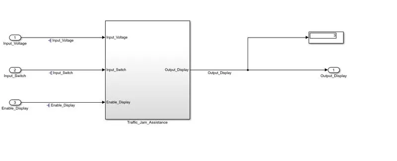
- In this main diagram it has one subsystem which is named as Traffic_Jam_Assistance.
- It has three inputs namely Input_Voltage, Input_Switch and Enable_Display.
- It has one output port Output_Display and one display block.
Now we will design the Requirement block and display unit.
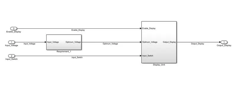
- The Traffic_Jam_Assistance subsystem has two subsystems namely Requirement_1 and Display units.
- It has three inputs namely Input_Voltage, Input_Switch and Enable_Display.
- It has one output port Output_Display.
The Requirement_1 subsystem would look like this -
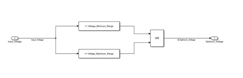
- It has two compare to constant blocks namely - Voltage_Minimum_Range and Voltage_Maximum_Range and is compared to OR block.
- And Input_Voltage and Optimum_Voltage are the input and output ports respetively.
- Input Signal “Input_Voltage” is compared against voltage values “VOLTAGE_MINIMUM_RANGE” & “VOLTAGE_MAXIMUM_RANGE”.
- Incoming input signal “Input_Voltage” must be greater than – equal to “VOLTAGE_MINIMUM_RANGE” and less than – equal to “VOLTAGE_MAXIMUM_RANGE”.
Display Unit would look like this -
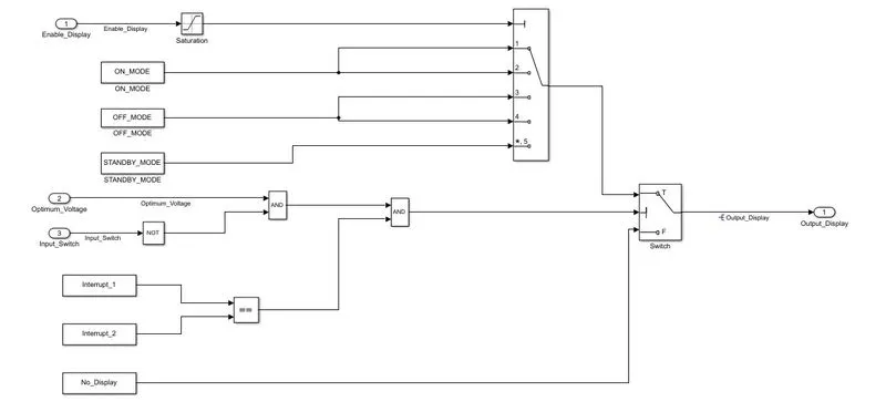
- The display Unit subsytem has three input ports, six constant blocks, multiport switch, logical operator blocks and output port.
- The constant blocks are named as ON_MODE, OFF_MODE and STANDBY_MODE.
- These above blocks are given as input to multiport switch.
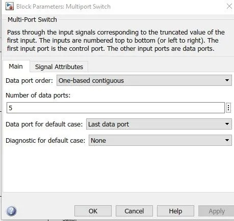
Set Diagnostic for default case to None.
- Interrupt 1 and 2 are given to relational operator block and No_Display block to switch.
- And output is observed.
Now we create a simulink data dictionary as shown. And saved it as TSA.sldd
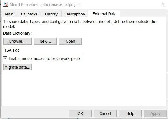
Now we will enter all the values in the simulink data dictionary as shown below.
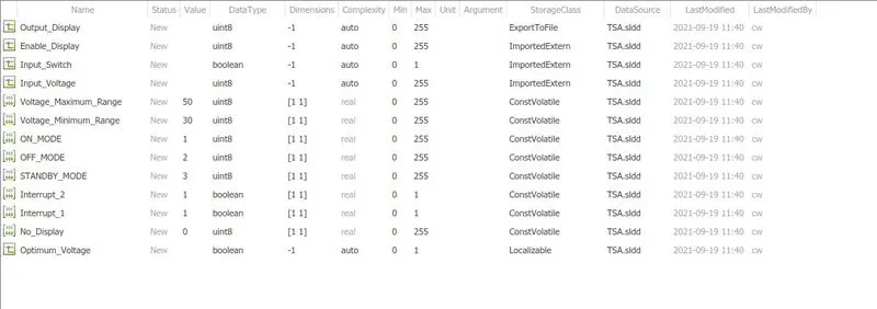
sldd file link - https://drive.google.com/file/d/1cI2K8pWZseSUxuFQomwwzelbTZdvFN_c/view?usp=sharing
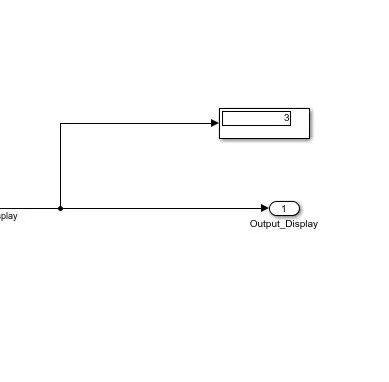
Now we will run the model and output is observed as shown.
Model Advisor Check -
- For the generation of model advisor check go to model settings.
- click on Solver type and select to fixed step.
- Now go to code generation, clock on system target and select ert.tlc
- Apply ok.
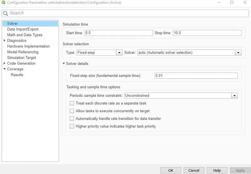
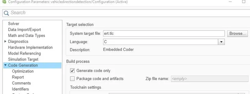
- Now go to the nodel advisor icon.
- Click on subsystem name and click on By product.
- Click on simulink and embedded coder and run the selected checks.
- Now click on generate report.
- We will get the model advisor check as shown below -
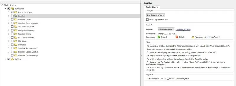
This is how the model advisor report would look like. with 31 passed cases and 0 failed cases. and 11 warnings.
In MATLAB command window the message comes as -
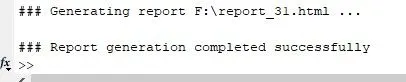
This shows that the model has no errors.
The model advisory report is attached below -
https://drive.google.com/file/d/1gp6ccZ__4SgFIxN9crmgV8YM0iM5KXLp/view?usp=sharing
Now to generate C -code we will perform SIL test.
Steps to perform SIL -
- In this method C- code is checked instead of cheking the test cases.
- Firstly right click on the subsystem and click on C++/C code and we should generate a S - function.
- Now the pop - up window comes and in that click on build option.
- Now the code gets generated.
- Copy the code or take the screen shot of that.
- This is how we perform the SIL by creating S - function.
Since embedded coder is not supporting in this version of software I am unable to attach the C -code generated.
The above model link is attached here - https://drive.google.com/file/d/1VWcRINmTWsRRcluD9y083bG-84zSKUZ9/view?usp=sharing
Conclusion - The desired model of Traffic Jam Assistant feature is created with all given data and requirements. All the supporting and required images are attached. All the required files are attached as links. The model is also attached as slx file. And the desired output is achieved.