Project-1: Powertrain for aircraft in runways
Part -A
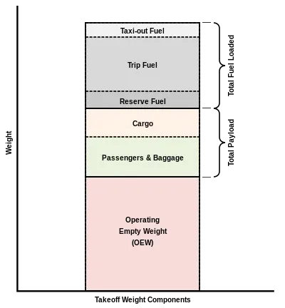
1. When looking at different aircraft's specifications or in POHs/AFMs, there are several different weights of the aircraft mentioned.
The different terms represent different weights or masses. For each flight, the weights are taken into account for several reasons.
(i) Manufacturer's empty weight (MEW) -
- It is the weight of the aircraft as built and includes the weight of the structure, powerplant, furnishings, installation, systems and other equipments that are considered as an integral part of an aircraft before additional operator items are added for operation.
- Basic aircraft empty weight is essentially the same and excludes any baggage, passengers or usable fuel. Some manufacturers define this empty weight as including optional equipment i.e GPS units,cargo baskets or spotlights.
(ii) Zero - fuel weight (ZFW) -
- This is the total weight of the airplane and all its contests (including unusable fuel), but excluding the total weight of the usable fuel on board.
- As a flight progresses and fuel is consumed, the total weight of the airplane reduces, but the ZFW remains constant.
- Maximum zero fuel weight (MZFW) is the maximum weight allowed before usable fuel and other specified usable agents (engine injection fluid, and other consumable propulsion agents) are loaded.
(iii) Operating empty weight (OEW) -
- Roughly equivalent to basic empty weight.
- It is the basic weight of an aircraft including the crew, all fluids necessary for operation such as engine oil, engine coolant water, unusable fuel and all operator items and equipment required for flight but excluding usable fuel and the payload.
(iv) Payload -
It is the carrying capacity of an aircraft. It includes cargo, people, extra fuel. In the case a commercial airlines, it may refer only to revenue - generating cargo or paying passengers.
(v) Maximum takeoff weight ( MTOW) -
- Is often referred to as maximum takeoff weight (MTOW), of an aircraft is a value defined by the aircraft manufacturer.
- It is the maximum mass at which the aircraft is certified for take off due to structural or other limits. MTOW is usually specified in units of kg or pounds.
(vi) Regulated takeoff weight (RTOW) -
- Depending on different factors (e.g flap setting, altitude, air temperature, length of runway) RTOW or maximum permissible take off weight varies for each take off.
- It can never be higher than MTOW.
(vii) Maximum landing weight (MLW) -
This maximum weight at which an aircraft is permitted to land.
(viii) Maximum ramp weight (MRW) -
- Also called as maximum taxi weight.
- It is the maximum weight authorized for mancuvering (taxing or towing) an aircraft on the ground.
(ix) Aircraft gross weight -
It is the total aircraft weight at any moment during the flight or ground operation. This decreases during flight due to fuel and oil consumption.
2. Difference between ground speed and air speed -
| Ground speed | Air speed |
| Grouns speed is the aircraft's speed relative to the ground. One thing that should be noted here is that it's horizontal rather than vertical speed. | It is the true air speed is simply the speed at which an aircraft is moving relative to the air it is flying in. |
| In other words, while airspeed is what determines whether there is enough air flow around an aircraft to make it fly, ground speed is what determines how fast an aircraft will get to its destination. | It is also the speed at which the air is flowing around the aircraft's wings. |
| Ground speed is the sum of air speed and wind speed. | Air speed is independent of ground speed. |
3. The aircraft engine power to move on the ground at airport is not recommended because of following reasons -
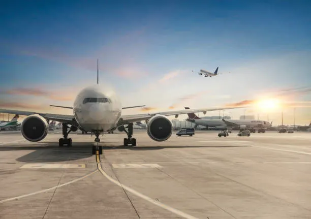
- For the movement on the ground the aircraft uses its own engine power, which is called taxing.
- Although many aircrafts are capable of moving in backward using reverse thrast as the result the jet blasts or prop wash might cause the damage to the terminal building or equipment. Engine close to ground may also blow sand and move forward and then stuck them into the engine, causing damage to the engine.
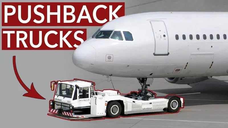
- Therefore, there are pushback trucks in the airport. A pushback truck lifts the front wheel of the aircraft, their role in the most airports is to move the aircraft away from the parking spot on to the taxiways, which is called towing.
- Unwanted situations mainly arising from the unintended movement of the aircraft during engine running like, effectively loss of control can happen, especially during high power engine running. Damage can occur to the aircraft itself other aircraft nearby ot to airside structures.
- Risk of injury to the ground support personnel who may be in the relatively close proximity to the aircraft.
- The plane engines are very loud, where more than one plane will add up their sound, than it will not be pleasant for passangers and other near airport.
4. An aircraft is pushed to runways with these steps when it is ready to takeoff -
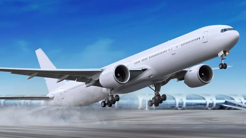
This picture shows how it is taking off :
Ten steps -
- The pilot parks the aircraft exactly in the right place. Usually with the help of an automatic system, but a ocassionally guided by a marshalller waving two paddles or wands. Dozens of handling personnel are already standing by to perform a whole range of tasks simultaneouly.
- As soon as the aircraft is stationary and the engines are switched off, the first priority is to disembark the passangers as quickly as possible. The apron handler places chocks in front of the wheels nd connects the ground power. Meanwhile, the passanger bridge manoevruses up to the door and a belt loader rolls up to the cargo hold. Luggage is unloaded and transffered to the terminal on baggage carts.
- Refuelling begins, usually from a hydrant at the stand. A hose is attached to this from a specific vehicle called a dispensor, with the other side connected to the fuel tank in the wing.
- Now it is time to service the aircraft. The carter loads new meals and takes away the food waste and used outley and crockery. Other activities include draining the lavatories, replacing the heardest covers, removing rubbish and distributing fresh blankets and in flight magazine.
- A specialist team - or sometimes the crew themselves - cleans the cabin so that the new passangers board a pristine aircraft.
- Meanwhile, specialists from the airline conduct a technical check to make sure that the engines, wings, control surfaces, landing gear, instruments, doors and other equipment are in full working order.
- The aircraft is now ready for baggage to be loaded for the next flight. This is a quick process, on average taking on;y 10 - 15 minutes. A little later the passangers start boarding. As soon as they all in their seats, the door is closed and the pilot informs air - traffic control that the flight is ready for departure.
- The apron handler removes the chocks. A so-called pushback truck reverses the aircraft into taxing positon, pushing it with a towbar attached to the nose-wheel strut. Or, in the most modern versions, by actually lifting the wheel. That speeds up coupling and decoupling.
- The aircraft taxis tothe runway to depart at the agreed time.
- The pilot waits for permission to take off from air-traffic control. This is possible once the departure route is clear. As soon as the go-ahead is recieved, the plane takes to the air at full power.
Finally, the mission will be accomplished.
5. Takeoff Power - The amount of power that an engine is allowed to produce for a limited period of time for takeoff. The use of takeoff power is usually limited to 5 minutes for reciprocating engines and upto two and half minutes for gas turbine engines.
- This may not aways be the case. Specifically, with respect to reciprocating engines, it is the brake horsepower developed under standard, sea - level conditions and under the maximum conditions of the crankshaft rotational speed and the engine mainfold pressure approved for the normal takeoff.
- It is imited in continuous use to the period of time shown in the approved engine specifications.
- With respect to gas turbine engines, it is the thrust developed under static conditions at a specified altitude and atmospheric conditions of the rotor shaft rotational speed and gas temperature approved for normal takeoff.
- It is limited in continuous use to the period of time shown in the approved engine specifications.
Tyre design - An aircraft tyre is designed to withstand extremely heavy loads for short durations. The number of tires are required for aircraft increases with the weight of the aircraft .
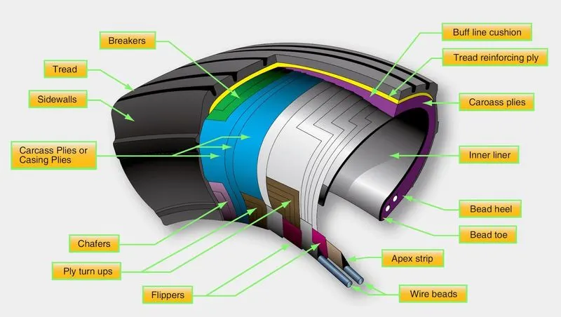
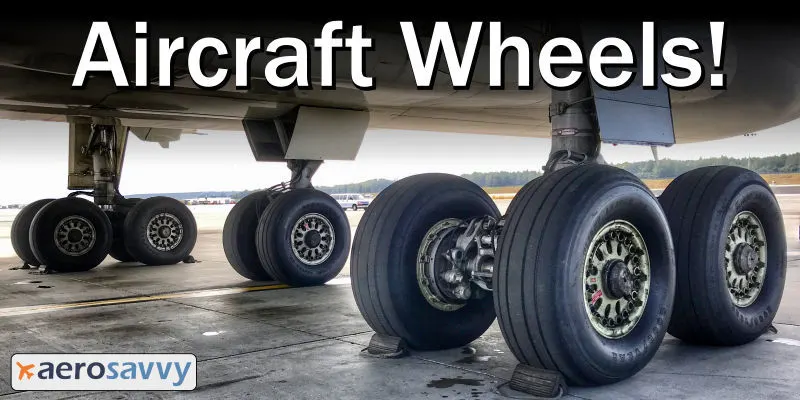
- As the weight of the aircraft needs to be distributed more evenly. Aircraft tire tread patterns are designed to facilitate stability in high crosswind conditions, to channel water away to prevent hydroplaning, and for braking effect.
- Aircraft tyres also include fusible plugs (which are assembled on the inside of the wheels), designed to melt at a certain temperature.
- Tyres often overheat if maximum braking is applied during an aborted takeoff or an emergency landing.
- The fuses provide a safer failure mode that prevents tire explosions by delating in a controlled manner, thus minimizing damage to aircraft and objects in the surrounding environment.
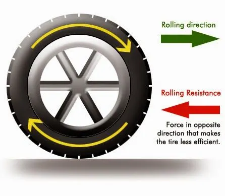
Rolling Resistance - It is also sometimes called rolling friction or rolling drag, is the force resisting the motion when a body (suc as ball, tire or wheel) rolls on a surface.
- It is mainly caused by non - elastic effects effects, that is, not all the energy meeded for deformation (or movement) of the wheel, roadbed, etc, is recovered when the pressure is removed.
- Two forms of this are hysterisis losses and permanent deformation of the object or the surface.
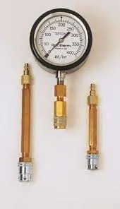
Tyre pressure - Aircraft tyres generally operate a high pressures, upto to 200 psi (14 bar; 1400 kPa) for airliners, and even higher for business jets. The main landing gear on the concorde was typically inflated to 232 psi (16.0 bar), whilst its tail bumper gear tires were as high as 294 psi(20.3 bar)
Brake forces when landing - Stopping a 200 - tonne aircraft landing at 180 mph requires a lot of braking force. To do this, the 787 has one brake unit on each of the eight wheels on the main gear assembly.
- On the other hand aircraft types, the brake units are powered by the hydraulics systems.
- An electrical signal is sent from the flight deck to hydraulic actuators near the main landing gear.
- Here, hydraulic fluid at 3000 pound per square inch is used to force the brake unit against the wheel, thus slowing it down.
- This system works fine, but the pipes and actuators that form this part of the hydraulic system come at a considerable weight cost.
- Electric brakes are also used where they send signals to the four electronic brake actuatir controllers (EBAC).
Part - B
6.
A. The forces required to push / pull an aircraft by a towing are Rolling Resistance Force and Aerodynamic Drag force
(i) Rolling resistance force - It is the force resisting the motion when a body (such as a ball, tire or wheel) rolls on a surface. The equations can be given as,
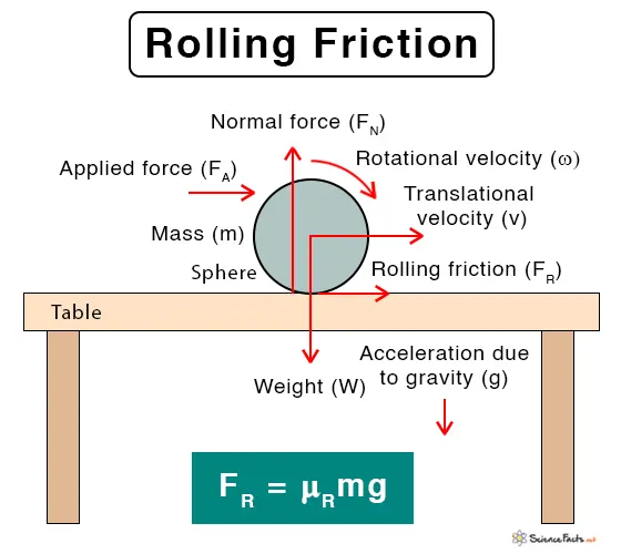
- The coefficient is a function of the tire material, tire structure, tire temperature, tire inflation pressure, tread geometry, road roughness, road materil and the predence or absence of liquids on the road.
- As the value varies with the speed, tire pressure increases and it's value decreases.
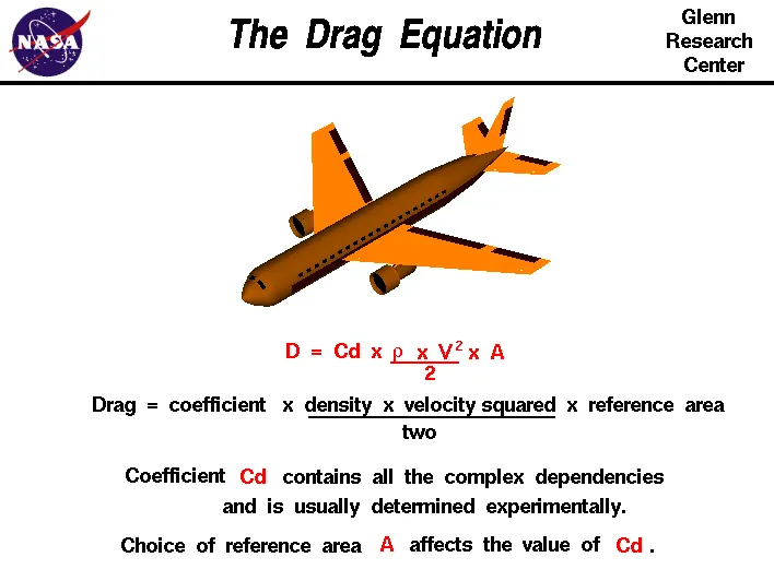
(ii) Aerodynamic Drag force - It is the force opposing the motion of the body. The drag coefficient is a common measure in automotive design as it pertains to aerodynamics.
- Drag is a force that acts parallel to and in the same direction as the airflow. The drag coefficient of an automobile measures the way the automobile passes through the surrounding air.
- When automobile companies design new vehicle, they take into consideration the automobile drag coefficient in addtion to the other performance charactristics.
- aerodynamic drag increses with the square of speed. Therefore, it becomes critically important at higher speeds. Reducing the drag coefficient in an automobile improves the perfirmance of the vehicle as it pertains to speed and fuel efficiency.
The governing equation is -
Calculations -
Assumptions -
- Mass of the towing vehicle = 45,000 kg
- Mass of an aircraft = 1,60,000 kg
Therefore, Total mass (m) = (45,000 + 1,60,000) kg
m = 2,05,000 kg
- Frontal area of the aircraft = (A) = 19 m^2
- Speed of the vehicle = (v) = 25 kmph
Speed in m/s, v = 25 * (1000/3600) = 6.94 m/s
- Drag coefficient, Cd = 0.75
- Air density = ρ = 1.225 kg/m^3
Now we will calculate the rolling resistance force , using the above formulae
Frr = (0.01 * 2,05,000 * 9.8)
Frr = 20,090 N
For Aerodynamic drag force,
Fd = (0.5 * 1.225 * 0.75* 19* 6.94 * 6.94)
Fd = 420.377 N
Thereforce total force required for push / pull an aircraft by towing is ,
F(total) = Frr + Fd
F(total) = 20,090 + 420.37
F (total) = 20,510.37 N
Total power required would be,
Power = F(total) * velocity
Power = (20,510.37 * 6.94)
Power = 142341.96
P = 142.341 kW
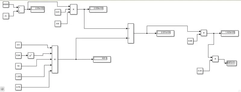
B. The simulink model for this calculated assumptions would be,
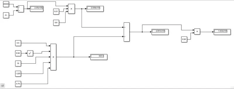
https://drive.google.com/file/d/1yWQIyM4zAed0GeLIcl3mpDPk9ygTSceD/view?usp=sharing
7.
A. As we discussed, An aircraft pushback vehicle is required to move aircrafts away from airport terminals. Powertrain is a system which covers all the drive train components which propels the vehicle. As the name suggests, the powertrain provides power to the vehicle. Powertrain refers to the set of components that generate the power required to move the vehicle and deliver it to the wheels.
Main componenets of an EV drivetrain -
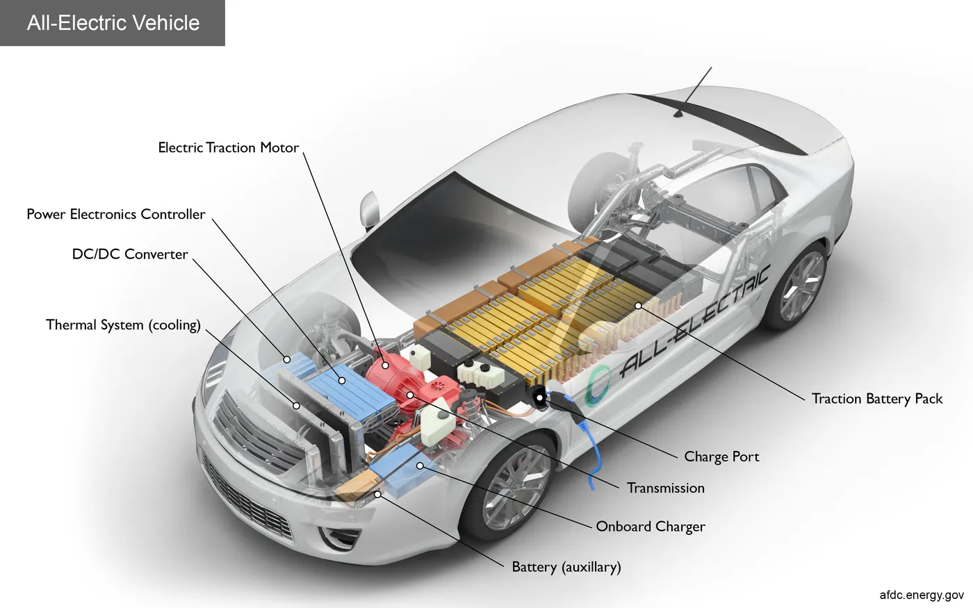
An EV powertrain has 60% fewer components than the powertrain of an ICE vehicle. The components are described below.
- Battery pack - The battery pack is made up of multiple Lithium - ion cells and stores the energy needed to run the vehicle. Battery packs provide direct current (DC) output.
- DC - AC converter - The DC supplied by battery pack is converted to AC and supplied to the electric motor. This power transfer is managed by a motor control mechanism (also known as powertrain electronic control unit) that controls the frequency and magnitude of the voltage supplied to the electric motor in order to manage the speed and acceleration as per driver's instructions communicated via accelertion / brakes.
- Electric motor - Convertrs electrical energy to mechanical energy, that is delivered to the wheels via single ratio transmission. Many EVs use motor generators that can perform regeneration as well.
- On - board Charger - Converts AC received through charge port to DC and controls the amount of current flowing into the battery pack.
Apart from the above core parts, there are multiple hardware and software components in an EV powertrain. Electronic Control Units (ECU) are basically softwre programs inegrated with the powertrain components to help data exchange and processing.
The communication between different ECU's in a vehicle is commonly carried over CAN protocol. More examples of core ECUs are -
- Battery Management System (BMS) - It continuously monitors the state of the battery and is responsible for taking neessary measures in case of malfunction. BMS performs cell balancing to deliver maximum efficiency from the battery pack. It is responsible for communication with other ECUs and sensors, as well as EVSEVs to control the charging input, check the current state of charge and share data about battery specifications.
- DC - DC Converter - A battery ack delivers a fixed voltage, but the reqiurement of different accessory systems (e.g wipers, lights, infotainment system, mirror control) in the EV would vary. The DC - DC converter helps distribute power to different systems by converting the output power from the battery pack to the expected level. After conversion, power is delivered to respective smaller ECUs via wiring harness.
- Thermal management system - Responsible for maintaning optimum operating temperature range from powertrain components.
- Body Control Module (BCM) - The BCM is responsible foe supervising and controlling the functions of electronic accessories such as power windows, mirrors, security ans=d vehicle access control.
Now we wil consider required parameters for designing an aircraft -
- Weight of an aircraft - 1,60,000 kg
- Weight of towing vehicle - 45,000 kg
- Rolling resistance coefficient of aircraft - 0.004
- Rolling resistance coefficient of towing vehicle - 0.01
- The velocity of the aircraft while towing - 6.94m/s
- Density of air medium - 1.225kg/m^3
- The frontal area of the aircraft - 19m^2
- The drag coefficient - 0.75
- Towing vehicle gear ratio - 11
- Towing vehicle tyre radius - 0.635 m
- Operational time of the towing for one cycle - 0.33 hours
- The battery armature voltage - 350V
- The battery armature current - 350 A
- The motor terminal voltage for full power output - 630V
- Power converters used - Bidirectional DC - DC boost converter
- The maximum duty cycle ratio for achieving full power - 70%
Considerthe operattional time for the towing truck is around 20 minutes for one duty cycle
20 minutes = 0.33 hour
Now we will calculate the energy required for this operation -
Energy = power * time
Energy = 142.341 * 0.33
Energy = 46.97 KWh
Therefore battery must be capable of storing 46.97 kwh energy. So, we will select the high performance ultra capacitors are selected to full fill the required power.
Motor Selection -
- Here we have selected a brushless DC motor type that has a power rating of126.8kw and battery voltage would be 350V and current 350A.
- For getting maximum power output from the motor, the voltage applied to the motor terminals must be 700 V.
Since we use DC-Dc boost converter to increase the voltage level from the battery to the required level so that when supplied to the motor we can get the desired power output from the motor. Thw bidirectional DC-DC converters find applications inplaes where battery charging, regenerative braking and backup power are required.
The electric vehicle uses power from the battery sorce to drive the motor and then further to drive the wheels in order to move the vehicle. The speed and torque generated from the motor is very important to drive the vehicle as per the driver's desire. If we connect the battery directly to the motor, the motor runs with a speed and torque charactristics which will be based on the fulll power of the battery voltage.
For controlling the vehicle power we use soft switching operations technique. The amount of power can be controlled by changing the duty cycle value. Considering the losses we take 70% of the duty cycle to deliver the maximum power of the motor.
Motor terminal voltage = Armature voltage * Duty Cycle
Motor terminal voltage = 900 * 0.7 = 630V
https://drive.google.com/file/d/1ciRAAylGTr6ixSubQpUm85wCvcueLjEQ/view?usp=sharing
B. The above calculations are made in execl sheet as-
https://drive.google.com/file/d/1plfEy1QSFTFUQ8mgWm-U0H2IKjdWXLrh/view?usp=sharing