Week 7 State of charge estimation
1.Simulate the 3 test cases from harness dashboard and write a detailed report on the results
2.What is coulomb counting? Refer to the above model and explain how BMS implements coulomb counting for SOC estimation ?
Answers
1. To Simulate the 3 test cases from harness dashboard and write a detailed report on the results.
BATTERY MANAGEMENT SYSTEM
A battery management system (BMS) is any electronic system that manages a rechargeable battery (Cell or battery pack), such as by protecting the battery from operating outside its safe operating area, monitoring its state, calculating secondary data, reporting that data, controlling its environment, authenticating it and / or balancing .
Monitor
A BMS may monitor the state of the battery as represented by various items, such as:
- Voltage: total voltage, voltages of individual cells, or voltage of periodic taps
- Temperature: average temperature, coolant intake temperature, coolant output temperature, or temperatures of individual cells
- Coolant flow: for air or fluid cooled batteries
- Current: current in or out of the battery
Electric vehicle systems: energy recovery
- The BMS will also control the recharging of the battery by redirecting the recovered energy (i.e.- from regenerative braking) back into the battery pack (typically composed of a number of battery modules, each composed of a number of cells).
Battery thermal management systems can be either passive or active, and the cooling medium can either be air, liquid, or some form of phase change. Air cooling is advantageous in its simplicity. Such systems can be passive, relying only on the convection of the surrounding air, or active, utilizing fans for airflow. Commercially, the Honda Insight and Toyota Prius both utilize active air cooling of their battery systems.[2] The major disadvantage of air cooling is its inefficiency. Large amounts of power must be used to operate the cooling mechanism, far more than active liquid cooling. The additional components of the cooling mechanism also add weight to the BMS, reducing the efficiency of batteries used for transportation.
Liquid cooling has a higher natural cooling potential than air cooling as liquid coolants tend to have higher thermal conductivities than air. The batteries can either be directly submerged in the coolant or coolant can flow through the BMS without directly contacting the battery. Indirect cooling has the potential to create large thermal gradients across the BMS due to the increased length of the cooling channels. This can be reduced by pumping the coolant faster through the system, creating a tradeoff between pumping speed and thermal consistency.[3]
Computation
Additionally, a BMS may calculate values based on the above items, such as:
- Voltage: minimum and maximum cell voltage
- State of charge (SOC) or depth of discharge (DOD), to indicate the charge level of the battery
- State of health (SOH), a variously-defined measurement of the remaining capacity of the battery as % of the original capacity
- State of power (SOP), the amount of power available for a defined time interval given the current power usage, temperature and other conditions
- State of Safety (SOS)
- Maximum charge current as a charge current limit (CCL)
- Maximum discharge current as a discharge current limit (DCL)
- Energy [kWh] delivered since last charge or charge cycle
- Internal impedance of a cell (to determine open circuit voltage)
- Charge [Ah] delivered or stored (sometimes this feature is called Coulomb counter)
- Total energy delivered since first use
- Total operating time since first use
- Total number of cycles
Communication
The central controller of a BMS communicates internally with its hardware operating at a cell level, or externally with high level hardware such as laptops or an HMI.
High level external communication are simple and use several methods:
- Different types of serial communications.
- CAN bus communications, commonly used in automotive environments.
- Different types of Wireless communications.
Low voltage centralized BMSs mostly do not have any internal communications.
Distributed or modular BMSs must use some low level internal cell-controller (Modular architecture) or controller-controller (Distributed architecture) communication. These types of communications are difficult, especially for high voltage systems. The problem is voltage shift between cells. The first cell ground signal may be hundreds of volts higher than the other cell ground signal. Apart from software protocols, there are two known ways of hardware communication for voltage shifting systems, Optical-isolator and wireless communication. Another restriction for internal communications is the maximum number of cells. For modular architecture most hardware is limited to maximum 255 nodes. For high voltage systems the seeking time of all cells is another restriction, limiting minimum bus speeds and losing some hardware options. Cost of modular systems is important, because it may be comparable to the cell price. Combination of hardware and software restrictions results to be a few options for internal communication:
- Isolated serial communications
- wireless serial communications
Protection
A BMS may protect its battery by preventing it from operating outside its safe operating area, such as:
- Over-current (may be different in charging and discharging modes)
- Over-voltage (during charging), especially important for lead–acid and Li-ion cells
- Under-voltage (during discharging)
- Over-temperature
- Under-temperature
- Over-pressure (NiMH batteries)
- Ground fault or leakage current detection (system monitoring that the high voltage battery is electrically disconnected from any conductive object touchable to use like vehicle body)
The BMS may prevent operation outside the battery's safe operating area by:
- Including an internal switch (such as a relay or solid state device) which is opened if the battery is operated outside its safe operating area
- Requesting the devices to which the battery is connected to reduce or even terminate using the battery.
- Actively controlling the environment, such as through heaters, fans, air conditioning or liquid cooling
Simulate the 3 test cases from harness dashboard
In order to simulate the three test cases from harness dash board
first download the model from the given link.
downloaded file will be in the zip file .
Add that zip file to the matlab path and open the files in it.
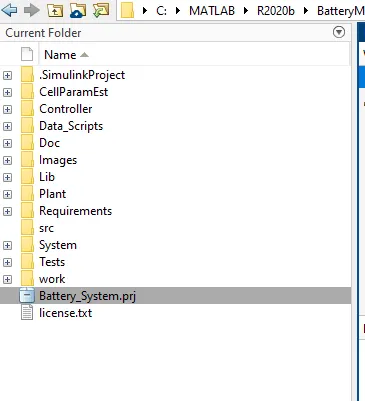
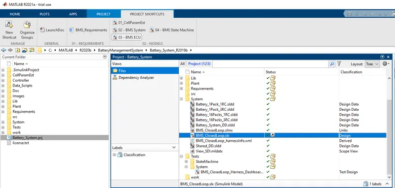
double click on 'battery_System.prj' all the files automatically added to the model.You can see in the below fig.
open the simulink model of the closed loop BMS and harness files. as shown in the fig.
We need to the change the test sequence variant to 1,2 &3 and then observe the results of each test case.
case1 :
Change the test sequence variant to 1.By double click on the test sequence variant as shown in the below fig.
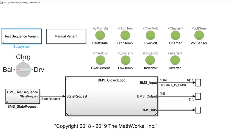
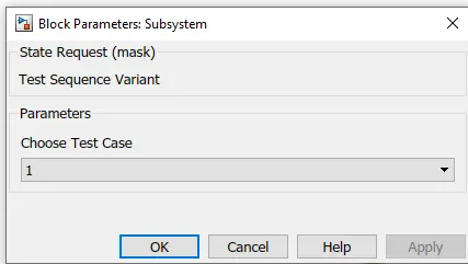
After changing the test sequence variant to 1. run the model
RESULTS:
In the result scope we can see following parameters
- Cell voltages
- cell temperatures
- SOC
- Pack current
- BMS state
- Balancing of the cells i.e balcmd
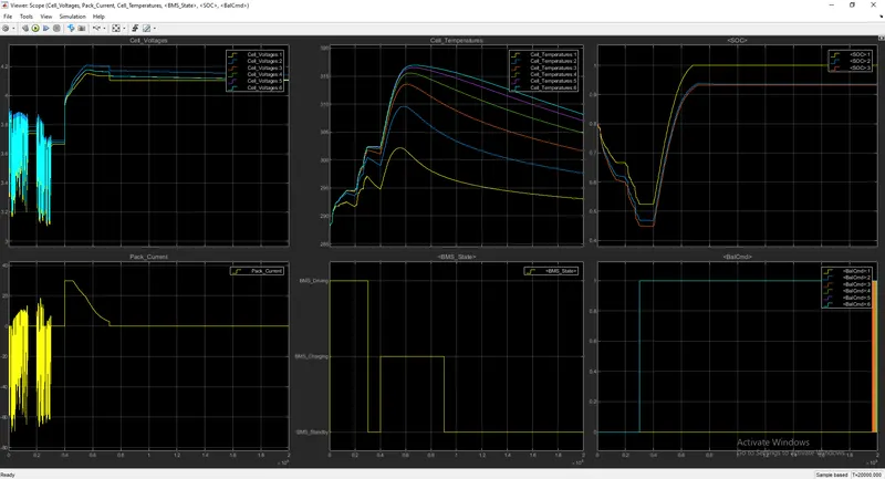
From 0 to 0.3 *10^4 secs
- BMS driving mode is in BMS driving mode.
- Cell voltages are varying from 3.2 v to 3.9 v.
- pack currents are fluctuating from 20 A to -60 A.
- cell temperatures are rises up to 300k temperature.
- SOC is reduced to 80% to 30% of the battery
- Balancing of all cells are balanced i.e; zero
From 0.3 *10^4 to 0.4 * 10^4 secs
- BMS driving mode is in BMS standby mode.
- Cell voltages are stable at 3.7 v.
- pack currents are stable at 0 A.
- cell temperatures are reduced slightly .
- SOC of the battery is contant. (No movement of the vehicle)
- Balancing of all cells are balanced i.e; zero except cell 6 is unbalanced.
From 0.4 *10^4 to 0.9 * 10^4 secs
- BMS driving mode is in BMS charging mode.
- Cell voltages are rises to 4.2 v.
- pack currents are suddenly rises to 30 A and then decreases slightly.
- cell temperatures are rises up to 315 k approximately .temperature and redues slightly.
- SOC of the all cells are rised to 100 % soc its capacity but cell 1 is 100% soc and cell 2 &3 are ~90% soc
while charging constant current and constant voltage charging modes are done, During constant current 0.4 to 0.5 secs soc is rises fastly but during constant voltage 0.5 to 0.9 soc is slightly rises.
- Balancing of all cells are balanced i.e; zero except cell 6 is unbalanced.
case2:
Change the test sequence variant to 2.By double click on the test sequence variant as shown in the below fig.
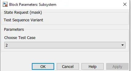
After changing the test sequence variant to 2. run the model
RESULTS:
In the result scope we can see following parameters
- Cell voltages
- cell temperatures
- SOC
- Pack current
- BMS state
- Balancing of the cells i.e balcmd
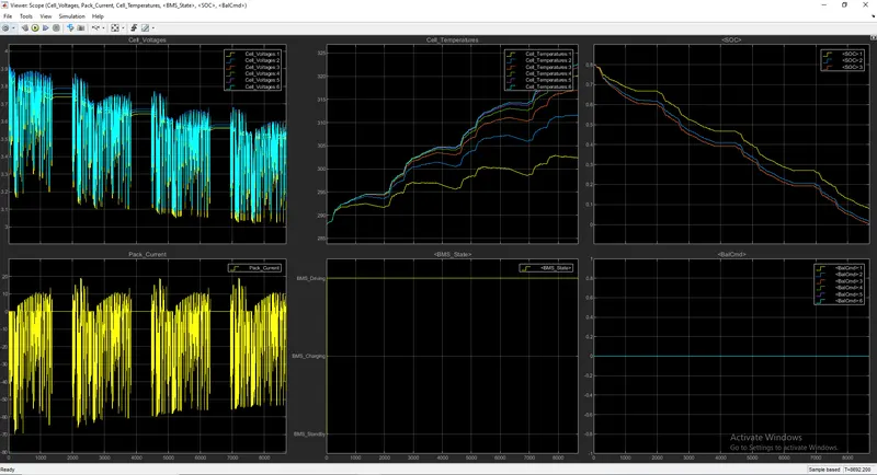
From starting to end
- BMS driving mode is in BMS driving mode.
- Cell voltages are varying from 3.2 v to 3.9 v having four fluctuation zones.
- pack currents are fluctuating from 20 A to -60 A having four fluctuation zones.
- cell temperatures are rises up to 325k temperature.
- SOC is reduced to 80% to 0% of the battery with in 8700 secs
- Balancing of all cells are balanced i.e; zero
CASE 3:
Change the test sequence variant to 2.By double click on the test sequence variant as shown in the below fig.
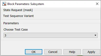
After changing the test sequence variant to 3. run the model
RESULTS:
In the result scope we can see following parameters
- Cell voltages
- cell temperatures
- SOC
- Pack current
- BMS state
- Balancing of the cells i.e balcmd
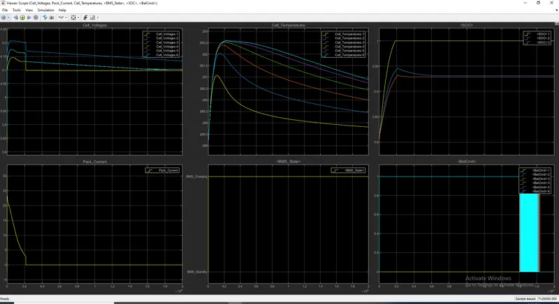
From starting to end
- BMS driving mode is in BMS Charging mode.
- Cell voltages are decreases from 4.2 v .
- pack currents are decreases from 20 A to 0 A.
- cell temperatures are rises up to ~292k temperature and then decrease slightly.
- SOC of the all cells are rised to 100 % soc its capacity but cell 1 is 100% soc and cell 2 &3 are ~90% soc
while charging constant current and constant voltage charging modes are done, During constant current 0 to 0.2 secs soc is rises fastly but during constant voltage 0.2 to 2 soc is slightly rises.
- Balancing of all cells are balanced i.e; zero except cell 6.
2.What is coulomb counting? Refer to the above model and explain how BMS implements coulomb counting for SOC estimation ?
Coulomb counting is a technique used to track the State of Charge of a battery pack. It works by integrating the active flowing current (measured in amps) over time to derive the total sum of energy entering or leaving the battery pack. This produces a capacity that is typically measured in Amp-hours.
Definition and Classification of SOC Estimation
The SOC is one of the most important parameters for batteries, but its definition presents many different issues [5]. In general, the SOC of a battery is defined as the ratio of its current capacity () to the nominal capacity (). The nominal capacity is given by the manufacturer and represents the maximum amount of charge that can be stored in the battery. The SOC can be defined as follows:
SOC(t)=Q(t)/Qn
The various mathematical methods of estimation are classified according to methodology. The classification of these SOC estimation methods is different in the various literatures. However, some literatures [5, 7] allow a division into the following four categories.(i)Direct measurement: this method uses physical battery properties, such as the voltage and impedance of the battery.(ii)Book-keeping estimation: this method uses discharging current as the input and integrates the discharging current over time to calculate the SOC.(iii)Adaptive systems: the adaptive systems are self-designing and can automatically adjust the SOC for different discharging conditions. Various new adaptive systems for SOC estimation have been developed.(iv)Hybrid methods: the hybrid models benefit from the advantages of each SOC estimation method and allow a globally optimal estimation performance. The literature shows that the hybrid methods generally produce good estimation of SOC, compared to individual methods.
Table 1 presents the specific SOC estimation methods in view of the methodology. The applications of specific SOC estimation methods in battery management system (BMS) are consequentially different.
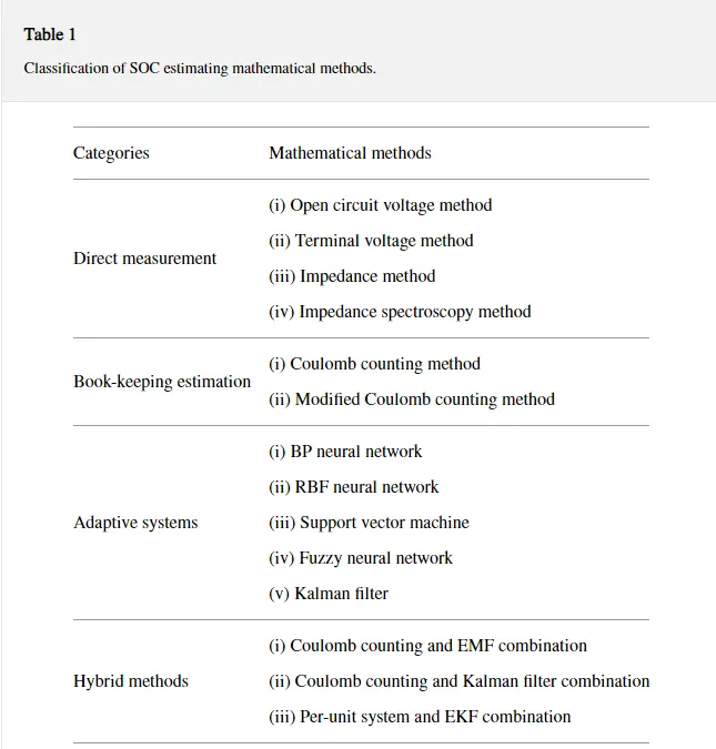
3. Overview of SOC Estimating Mathematical Methods
3.1. Direct Measurement
Direct measurement methods refer to some physical battery properties such as the terminal voltage and impedance. Many different direct methods have been employed: open circuit voltage method, terminal voltage method, impedance measurement method, and impedance spectroscopy method.
3.1.1. Open Circuit Voltage Method
There is approximately a linear relationship between the SOC of the lead-acid battery and its open circuit voltage (OCV) given bywhere is the SOC of the battery at , is the battery terminal voltage when SOC = 0%, and is obtained from knowing the value of and at SOC = 100%. By
Voc(t)=a1*soc(t)+a0.
(2), the estimation of the SOC is equivalent to the estimation of its OCV [8]. The OCV method based on the OCV of batteries is proportional to the SOC when they are disconnected from the loads for a period longer than two hours. However, such a long disconnection time may be too long to be implemented for battery [9].
Unlike the lead-acid battery, the Li-ion battery does not have a linear relationship between the OCV and SOC [10]. A typical relationship of Li-ion battery between SOC and OCV is shown in Figure 1 [11]. The OCV relationship with SOC was determined from applying a pulse load on the Li-ion battery, then allowing the battery to reach equilibrium [12].
The relationship between the OCV and SOC cannot be exactly the same for all batteries. Because the conventional OCV-SOC differs among batteries, there is a problem in that the relationship of the OCV-SOC should be measured to estimate accurately the SOC. Lee et al. [13] proposed a modified OCV-SOC relationship based on the conventional OCV-SOC. The SOC and the capacity of a lithium-ion battery are estimated using the dual extended Kalman filter with the proposed method.
3.1.2. Terminal Voltage Method
The terminal voltage method is based on the terminal voltage drops because of the internal impedances when the battery is discharging, so the electromotive force (EMF) of battery is proportional to the terminal voltage. Since the EMF of battery is approximately linear proportional to the SOC, the terminal voltage of battery is also approximately linear proportional to the SOC. The terminal voltage method has been employed at different discharge currents and temperatures [14]. But at the end of battery discharge, the estimated error of terminal voltage method is large, because the terminal voltage of battery suddenly drops at the end of discharge [15].
3.1.3. Impedance Method
Among the techniques which have been employed, impedance measurements provide knowledge of several parameters, the magnitudes of which may depend on the SOC of the battery. Although the impedance parameters and their variations with SOC are not unique for all battery systems, it appears to be imperative to perform a wide range of impedance experiments for identification and use of impedance parameters for estimating the SOC of a given battery [16, 17].
3.1.4. Impedance Spectroscopy Method
The impedance spectroscopy method measures battery impedances over a wide range of ac frequencies at different charge and discharge currents. The values of the model impedances are found by least-squares fitting to measured impedance values. SOC may be indirectly inferred by measuring present battery impedances and correlating them with known impedances at various SOC levels [18, 19].
3.2. Book-Keeping Estimation
Book-keeping estimation method uses battery discharging current data as input. This method permits to include some internal battery effects as self-discharge, capacity-loss, and discharging efficiency. Two kinds of book-keeping estimation methods have been employed: Coulomb counting method and modified Coulomb counting method.
3.2.1. Coulomb Counting Method
The Coulomb counting method measures the discharging current of a battery and integrates the discharging current over time in order to estimate SOC [20]. Coulomb counting method is done to estimate the , which is estimated from the discharging current, , and previously estimated SOC values, . SOC is calculated by the following equation:

But there are several factors that affect the accuracy of Coulomb counting method including temperature, battery history, discharge current, and cycle life [20].
3.2.2. Modified Coulomb Counting Method
To improve the Coulomb counting method, a new technique called modified Coulomb counting method is proposed. The modified Coulomb counting method uses the corrected current to improve the accuracy of estimation.
The corrected current is the function of discharging current. There is a quadratic relationship between the corrected current and discharging current of battery. By practice of experimental data, corrected current is calculated by the following form:

where ,k1,k2 and k0 are constant values obtained from the practice experimental data.
In modified Coulomb counting method, SOC is calculated by the following equation:

The experimental results show that the accuracy of the modified Coulomb counting method is superior to the conventional Coulomb counting method.
3.3. Adaptive Systems
Recently, with the development of artificial intelligence, various new adaptive systems for SOC estimation have been developed. The new developed methods include back propagation (BP) neural network, radial basis function (RBF) neural network, fuzzy logic methods, support vector machine, fuzzy neural network, and Kalman filter. The adaptive systems are self-designing ones that can be automatically adjusted in changing systems. As batteries have been affected by many chemical factors and have nonlinear SOC, adaptive systems offer good solution for SOC estimation [5].
3.3.2. RBF Neural Network
The RBF neural network is a useful estimation methodology for systems with incomplete information. It can be used to analyze the relationships between one major (reference) sequence and the other comparative ones in a given set. The RBF neural network has been used in SOC estimation. The method was tested with data which was from battery experiments. Results show that the operation speed and estimation accuracy of estimating model can meet the demands in practice, and the model has certain value of application [23, 24].
In [1], the RBF neural network SOC estimation method uses the input data of the terminal voltage, discharging current, and temperature of battery to estimate the SOC for LiFePO4 battery under different discharging conditions. The experimental data are found to be in close agreement.
3.3.3. Fuzzy Logic Method
Fuzzy logic method provides a powerful means of modeling nonlinear and complex systems. In [25], a practical method of estimating SOC of battery system has been developed and tested for several systems. The method involves the use of fuzzy logic models to analyze data obtained by impedance spectroscopy and/or Coulomb counting methods. In [26], a fuzzy logic-based SOC estimation method has been developed for lithium-ion batteries for potential use in portable defibrillators. The ac impedance and voltage recovery measurements have been made which are used as the input parameters for the fuzzy logic model.
Singh et al. [27] presented an estimation system which can select features in data base to develop fuzzy logic models for both available capacity and SOC estimation, simply by measuring the impedance at three frequencies. In [28], the SOC is estimated by an improved Coulomb metric method, and the time-dependent variation is compensated by using a learning system. The learning system tunes the Coulomb metric method in such a way that the estimation process remains error free from the time-dependent variation. The proposed learning system uses the fuzzy logic models, which is not used for estimation of SOC but performs as a component of learning system.
3.3.4. Support Vector Machine
The support vector machine (SVM) has been applied for classification in various domains of pattern recognition. The SVM has also been applied for regression problem, even the regression problem inherently more difficult than classification problem. The SVM used as a nonlinear estimation system is more robust than a least-squares estimation system because it is insensitive to small changes [29].
Hansen and Wang [29] investigated the application of a SVM to estimate the SOC of lithium-ion battery. The SVM based estimator not only removes the drawbacks of the Coulomb counting SOC estimator but also produces accurate SOC estimates.
3.3.5. Fuzzy Neural Network
Fuzzy neural network (FNN) has been used in many applications, especially in identification of unknown systems. In nonlinear system identification, FNN can effectively fit the nonlinear system by calculating the optimized coefficients of the learning mechanism [30].
Lee et al. [31] investigated a soft computing technique for estimating battery SOC of individual batteries in a battery string. The soft computing approach uses a fusion of an FNN with B-spline membership functions and a reduced-form genetic algorithm.
3.3.6. Kalman Filter
Using real-time measurement road data to estimate the SOC of battery would normally be difficult or expensive to measure. In [32], application of the Kalman filter method is shown to provide verifiable estimations of SOC for the battery via the real-time state estimation.
Yatsui and Bai [33] presented a Kalman filter based SOC estimation method for lithium-ion batteries. Experimental results validate the effectiveness of Kalman filter during the online application. Barbarisi et al. [34] presented an extended Kalman filter (EKF) to estimate the concentrations of the main chemical species which are averaged on the thickness of the active material in order to obtain the SOC of the battery, by using the terminal current and voltage measurements.
Based on unscented Kalman filter (UKF) theory and a comprehensive battery model, a novel SOC estimation method is proposed in [35]. The results show that UKF method is superior to extended Kalman filter method in SOC estimation for battery. Sun et al. [36] presented an adaptive UKF method to estimate SOC of a lithium-ion battery for battery electric vehicles. The adaptive adjustment of the noise covariance in the SOC estimation process is implemented by an idea of covariance matching in the UKF context.
3.4. Hybrid Methods
The object of hybrid models is to benefit from the advantages of each method and obtain a globally optimal estimating performance. Since the information contained in the individual estimating method is limited, hybrid method can maximize the available information, integrate individual model information, and make the best use of the advantages of multiple estimating methods thus improving the estimation accuracy. The literatures show that the hybrid methods generally produce good SOC estimating results compared to individual methods [37–39]. The hybrid methods combine different approaches such as direct measurement method and book-keeping estimation method.
3.4.1. Coulomb Counting and EMF Combination
A new SOC estimation method that combines direct measurement method with the battery EMF measurement during the equilibrium state and book-keeping estimation with Coulomb counting method during the discharge state has been developed and implemented in a real-time estimation system [37].
Any battery will lose capacity during cycling. In order to calculate SOC and remaining run-time (RRT) accurately and to improve the SOC estimation system capability to cope with the aging effect, a simple Qmax adaptation algorithm is introduced. In this algorithm the stable conditions of the charge state are exploited in order to adapt Qmax with the aging effect.
This paper has proved that the Qmax adaptation algorithm can improve the SOC and RRT estimation accuracy even for a fresh battery. Since a battery loses capacity during cycling, it is concluded that the Qmax adaptation algorithm will increase substantially the SOC and the RRT estimation accuracy.
3.4.2. Coulomb Counting and Kalman Filter Combination
Wang et al. [38] proposed a new SOC estimation method, denoted as “KalmanAh method,” which uses the Kalman filter method to correct for the initial value used in the Coulomb counting method. In KalmanAh method, the Kalman filter method is used to make the approximate initial value converge to its real value. Then the Coulomb counting method is applied to estimate the SOC for the long working time. The SOC estimation error is 2.5% when compared with the real SOC obtained from a discharge test. This compares favorably with an estimation error of 11.4% when using Coulomb counting method.
3.4.3. Per-Unit System and EKF Combination
Kim and Cho [39] described the application of an EKF combined with a per-unit (PU) system to the identification of suitable battery model parameters for the high accuracy SOC estimation of a lithium-ion degraded battery. To apply the battery model parameters varied by the aging effect, based on the PU system, the absolute values of the parameters in the equivalent circuit model in addition to the terminal voltage and current are converted into dimensionless values relative to a set of base value. The converted values are applied to dynamic and measurement models in the EKF algorithm.
Refer to the above model and explain how BMS implements coulomb counting for SOC estimation
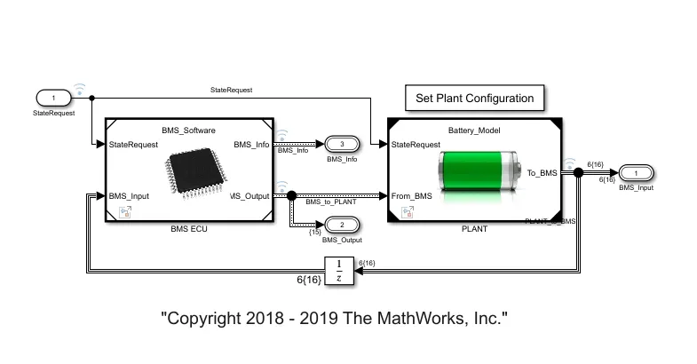
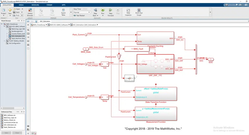
Before we charge our vehicle we need an accurate Estimation of battery SOC, in the battery system we don't measure the state of charge we measure different things like battery pack current cell voltage and cell voltage which we taking signals as input from the plant.
In BMS ECU we can see the state machine, SOC estimation and balancing logic.
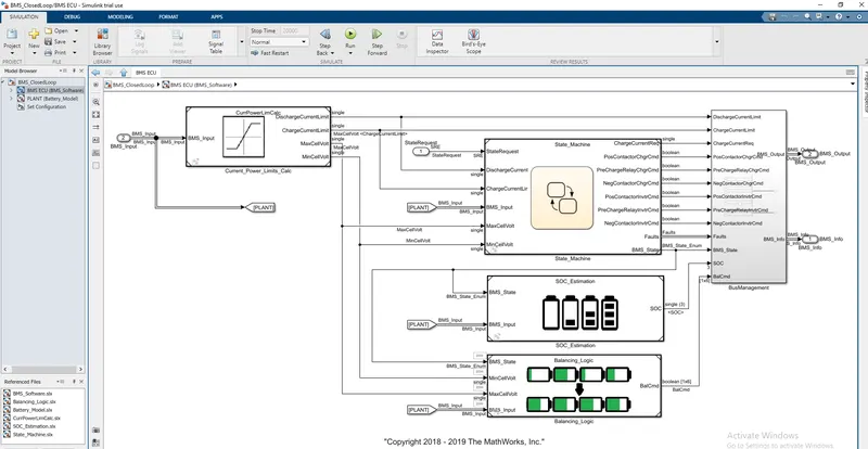
In this SOC estimation block we can see three different techniques for the state of charge estimation. all three techniques have their own merits and limitations. the first method is columb counting and the other two are unscented(ukf) and extended Kalman filter(ekf).here we are concern with the columb counting method.
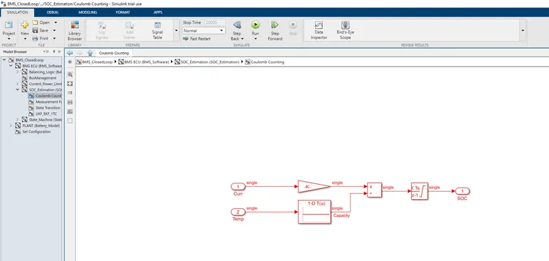
It takes two input signals such as current and temp and the current signal goes to gain block and the temp signal goes to lookup tables of battery time and current. and both the blocks are connected to the divided block and these signals are connected to the discrete-time integrator to track the charge and which finally helps to calculate the state of charge.
which consist of integrating a current and doesn't leave the cell for that here we using discrete-time integrator to give the track of the cell charge of the time the benefits of this is its simplicity and its low capitation cost and the drawbacks are an accumulation of current sensor error and its inability to recover from the wrong initial condition. from the lack of feedback from voltage measurements.
Conclusion
1.Simulate the 3 test cases from harness dashboard and write a detailed report on the results are done successively.
2 Coulomb counting and Refer to the above model and explain how BMS implements coulomb counting for SOC estimation are explained.