Week -2
- Make a Simulink model of Doorbell using solenoid block with the following details:
In the above arrangement, when the switch is closed the electromagnet receives electrical power from the battery and pulls the metal arm to hit the bell producing sound.
Create a situation where the switch is closed for 2 seconds and then released. Observe the physical movement of the plunger.
Assume remaining parameters.
2. Use a thermistor to sense the temperature of a heater & turn on or turn off the fan as per below conditions:
Temperature source: 20 °C from 0 to 10 seconds, 27 °C from 10 to 30 seconds, 23 °C from 30 to 50 seconds
Fan conditions: ON if the temperature above 25 °C, OFF otherwise
ANSWERS
1.
AIM: To design a simulink model of Doorbell using solenoid block.
MAIN ELEMEMTS: Pulse generator, battery, switch, solenoid, ideal translation motion sensor , PS-simulink converter, simulink-PS converter, solver configuration, mehanical translation reference, electrical reference and scope.
CONSTRACTION: According to the fig. connect the parameters.
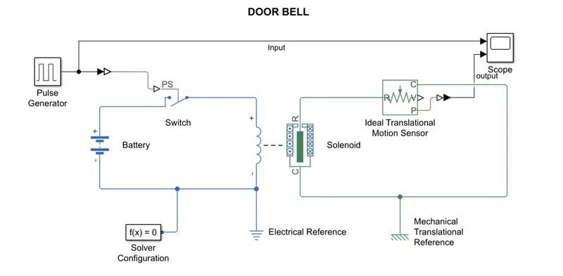
Here is the design of door bell using solenoid and we have make few changes in order to close the switch for 2 secounds and then release.The threshold valve of switch must lesser than phsyical signal then and only the switch will close . So we need a pulse generator , in that pulse generator change the period = 4 and pulse width = 50% i.e; the pulse width is of 2 seconds and amplitude = 2.In the solenoid change the direction i.e; the port moves away from the port c.Ideal translational motion sensor to sense the motion plunger without sensor we cannot get the results.PS-simulink converter and simulink-PS converter are to used for change of simulink to simscape and vise-versa.Solver configuration is must and connect to the input side at the bottom , electrical and mehanical translational references are connected to the case points respectively. pulse generator signal is take as input and connect to the scope, "p" port i.e; position of plunger is connect to scope as well to show resultant graphs .
WORKING:
Solenoid
Basically solenoid is a coil ,it is in the shape of cylindrial form and when the coil carried with some specfied current then it acts as a magnet so that a movable core drawn into the coil i.e; plunger.Solenoid is a electromagnetic device which converts the electrical energy to mechanical energy.
In the figure we can see that the coil of the solenoid is connect to the battery and a switch between them to allow current for a period of 2 secounds. As the switch is closed the current flows throught the coil which produce the magnetic field as a result the plunger will moves. If the switch is open plunger again goes to it oiginal position.
Damper is a device which reduces the vibrations so in the solenoid block we change the value of damper to reduce the vibrations or to increase the vibrations.Always value of the damper must be greater in order to eliminate the vibrations as to develop the efficiency of machine od element.
RESULT:
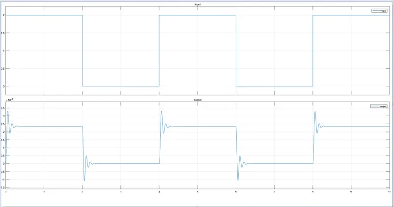
Hence the resultant graphs as shown in the fig. By the graph we can say that solenoid is working for 2 secounds and we can observe the positions of plunger by the secound graph ie; output graph.
2. AIM: To sense the temperature of the heater using thermistor and to control the fan at the particular conditions.
APPARATUS:
- Signal builder
- Controlled temperature source
- Temperature source
- Thermistor
- Voltage source
- Voltage sensor
- Solver configuration
- Resistor
- Batttery
- Switch
- Current sensor
- scope
CONSTRACTION:
Given conditions
Temperature source: 20 °C from 0 to 10 seconds, 27 °C from 10 to 30 seconds, 23 °C from 30 to 50 seconds
Fan conditions: ON if the temperature above 25 °C, OFF otherwise
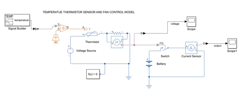
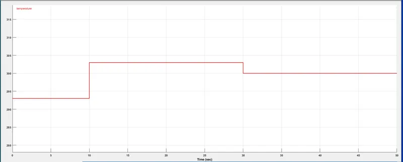
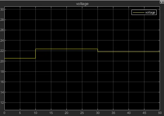
In order to get the particular signal of given conditions we must use signal builder, first change the scale of time to 50 secounds and then by changing the Y and T values we can built it.W.K.T zero degree celsius = 273 kelvins.Connect the signal builder to the controlled temperature source at port 's' and at port 'A' connect the temperature source and vary the value of tempearture =273k and connect to the 'A' port of thermistor , resistor with voltage sensor across it.Connect the voltage source(100V) to thermistor and resistorrespectively.Design another circuit of fan , take the switch connect with the current sensor and battery and in the switch change the threshold value to 22.Take 2 scopes connect one for voltage sensor and current sensor.Connect the solver configuration and the reference to the both the circuits.
signal builder graph:
Output graph of voltage sensor is given as a phsical signal to the switch.
WORKING:
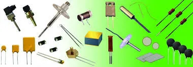
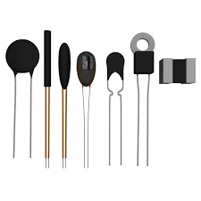
THERMISTOR: Thermistor is also known as resistance thermometer, in which whose resistance is dependence on temperature.Its term is a combination of 'thermal' and 'resistor'.It is made with metallic oxides,compress into a bead,disk and cylindrical shape and then contain with an impermeable material like epoxy and glass.
In the model thermistor sense the temperature of the resistor and we cann't give that sensed temperature as input , so we had connect the voltage sensor across the resistor and signal which is result of voltage sensor is given as input to the switch.Here in the 2nd circuit current sensor is represented as a fan ,therefore when switch is closed the fan will run accordingly to the given conditions.Thershold value of switch is 22 , switch will close for 10 to 30 secounds as the value is greater than thershold value.
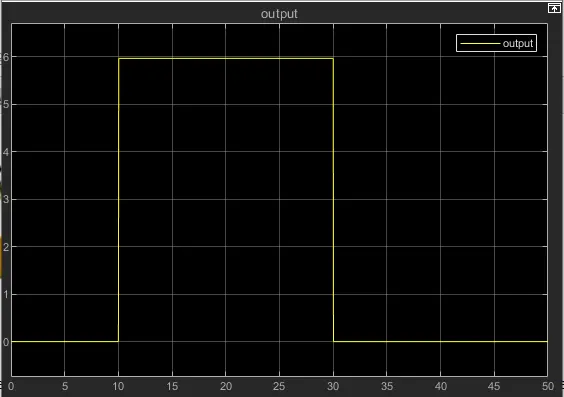
Hence the fun will ON if the temperature is above than 25 degreee celsius and if temperature is below the 25 degree celsius
the fun doesn't get supply , current sensor will shows zero value during that period.
RESULT:
Hence the control of fan using thermistor to sense the temperature of heater is done succesfully.Here is the resultant graph is ploted between current and time
CONSLUSION:
- Hence a Simulink model of Doorbell using solenoid block , to create a situation where the switch is closed for 2 seconds and then released is done successfully. Observation the physical movement of the plunger is obtained by output graph.
2. Hence by Using a thermistor to sense the temperature of a heater & turn on or turn off the fan is done successfully as per following conditions:
Temperature source: 20 °C from 0 to 10 seconds, 27 °C from 10 to 30 seconds, 23 °C from 30 to 50 seconds
Fan conditions: ON if the temperature above 25 °C, OFF otherwise