Week - 4
- Implement control logic of a “washing machine” using Stateflow as per given sequence:
- If the power supply is available, the system gets activated
- If the Water supply is not available, stop the process & indicate through LED
- Soaking time should be 200s followed by Washing time of 100s.
- Then rinsing happens for next 20s & dryer runs for 50s
After all the processes have completed turn on the finished LED
2. Make a Simulink chart for the “Gear shift” logic as per below conditions:
Speed Range(kmph) Gear
0 to 15 1
16 to 25 2
26 to 40 3
41 to 60 4
Above 61 5
Give speed input while the simulation is running & display the gear number.
ANSWERS
1.AIM:
- To implement control logic of a “washing machine” using Stateflow as per given sequence:
- If the power supply is available, the system gets activated
- If the Water supply is not available, stop the process & indicate through LED
- Soaking time should be 200s followed by Washing time of 100s.
- Then rinsing happens for next 20s & dryer runs for 50s
APPARATUS:
- Constant
- State flow chart
- Display
- Lamp
EXPLANATION:
WASHING MACHINE
A machine which is used for cleaning the clothes is known as waching machine.It is a home appliance and in many commerical buildings.
There are few processing steps in the machine.those are:
WASHING MACHINE
- Soaking
- Washing
- Rinsing
- Drying
Soaking is the process of allowing water to become thoroughly wet by immersing clothes in the liquid.
Washing is the action of cleaning the clothes or objects
Rinsing is washing the clothes with clean water to remove soap,detergent,dirt,impurities....
Drying is a process of drying clothes i.e; removing the water from clothes.
Open the chart in the simulink model and design the logic in that chart .
Logic design of the washing machine in that chart is shown as below.
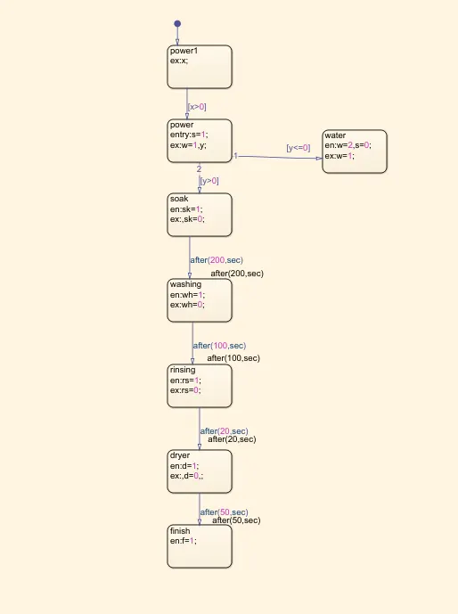
Box which is appeared on the chart is state.In state ,we can change name of state and entry or en are keywords for output of a particular state and ex or exit are keywords for when a state is exited as the response of a transition taken away from the state.Conditions and timing is done by using double on the transition line or right click on the transition line ->properties->write conditions in label box as shown below.
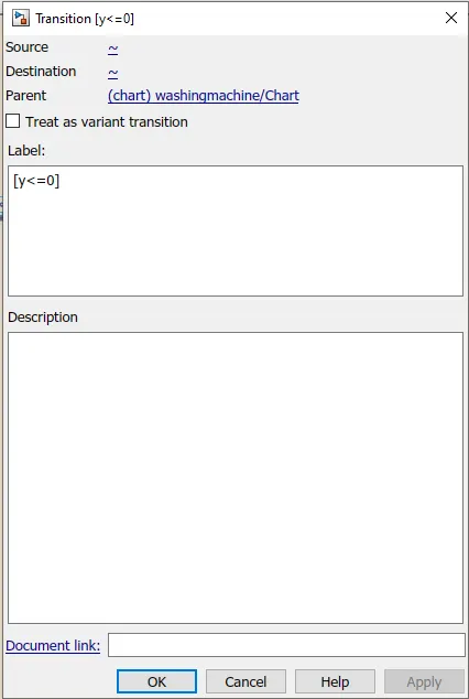
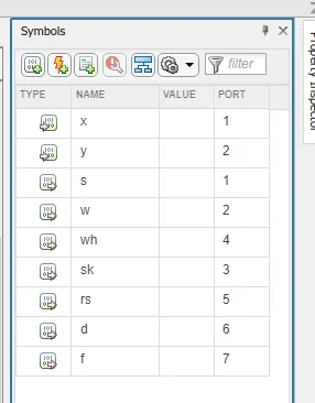
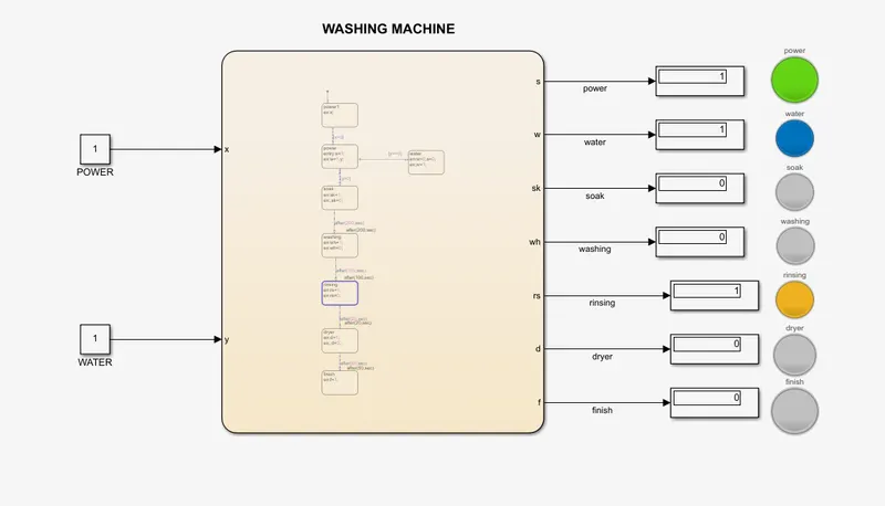
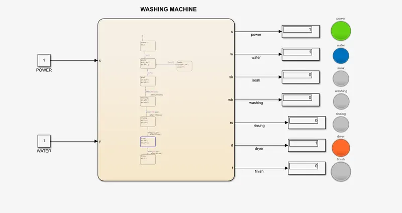
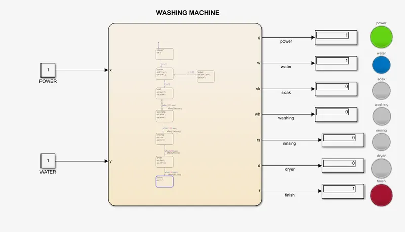
In the state one ,name 'power1' and logic ex:x; so the first state just send value of x to the next state.To the transition line first state to 2nd state ,condition x>0 so when the x is greater than zero than only it allow to the next step as x=1 it allows to the next step.Second state is power , logic en:s=1 and ex:y,w=1 , 's' power is on and sent w,y values to the next state.In water state in this it checks whether the water is available or not, logic en:w=2,s=0.In next state soak ,soaking is done when the water is available so condition is y>0 of the transition line and logic en:sk=1 , ex:sk=0.To the washing state after 200secs by entering the 'after(200,secs)' in label of transition line between soak and washing.washing is done logic en:wh=1,ex:wh=0 .duration of washing is 100secs and to rinsing state logic en sk=1 ,ex sk=0 and duration is 20secs .next state is dryer logic d=1,ex d=0 ,durations is 50secs. and then last state finish logic is en f=1.All the input variables and output variables are to defined in the symbol plane.
In this model x is power and y is water supply.All displays and lamps are connected respectively to outputs of the chart.
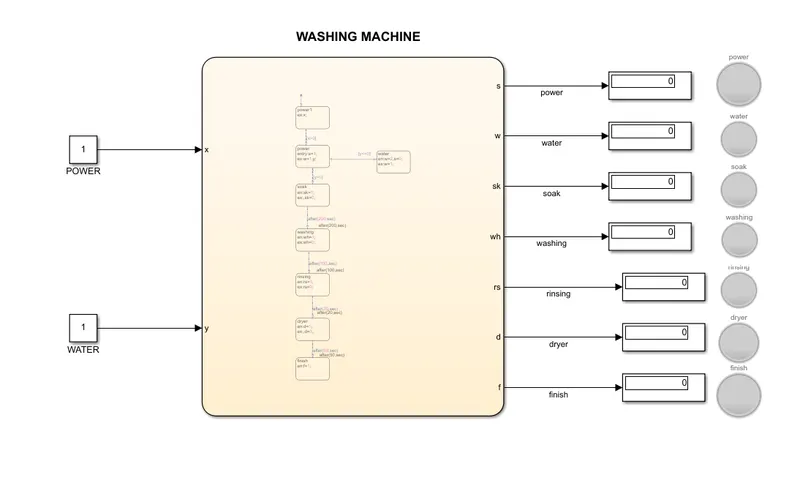
RESULTS:
a. Power is on (s=1) ,power lamp will glow.
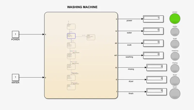
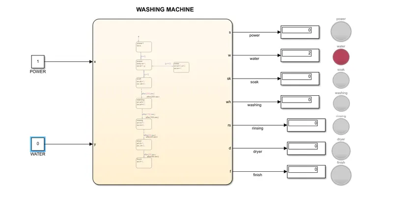
b. Lamp which is connected to the water ,shows blue when water is available and red when water is not available.
In the below fig. water value is zero , no water red will glow.
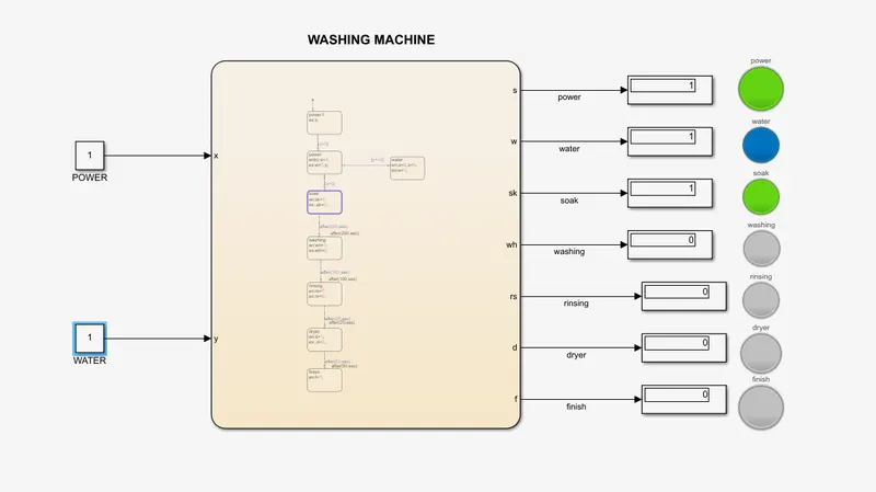
c.Soaking is done for 200 secs and washing for 100secs
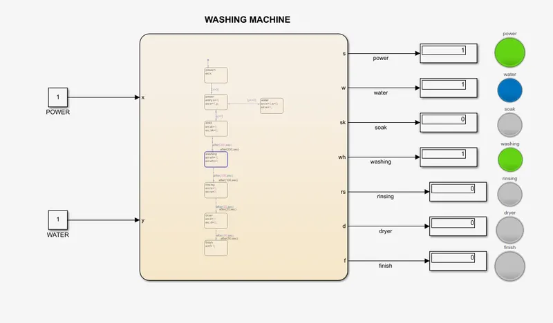
d.Rinsing for 20secs and dryer for 50secs
After all the process finish lamp will glow.
2.AIMS:To make a Simulink chart for the “Gear shift” logic as per below conditions:
Speed Range(kmph) Gear
0 to 15 1
16 to 25 2
26 to 40 3
41 to 60 4
Above 61 5
Give speed input while the simulation is running & display the gear number.
APPARATUS:
- Constant
- Slider gain
- State flow chart
- display
- Lamp
EXPLANATION:
GEAR BOX: It contains gear train or mechanical unit and function like a system alters torque and speed between a driving device like motor and a load.it plays a very important role in the transmission .
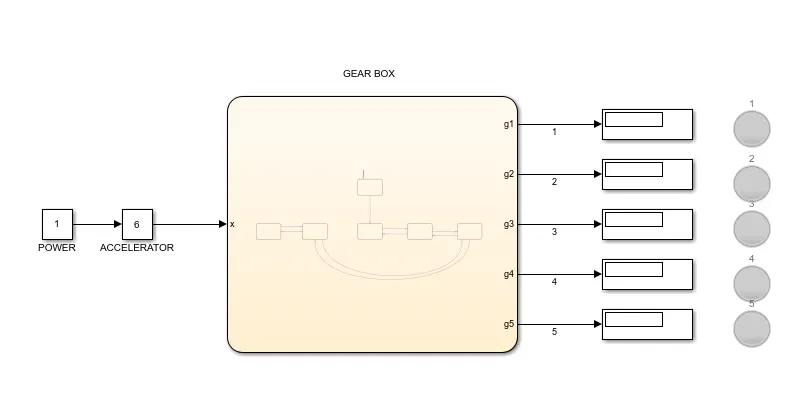
This is the model of the gear shift,here constant is power and slider gain is accelerator.Chart input x and outputs are g1,g2,g3,g4 and g5 as shown in the fig.
In the state flow chart let see the logic,
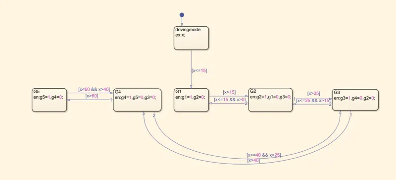
First state driving mode just send the value of x to the next state G1 , it checks whether the speed is between 0 -15 kmph and lamp is glow blue if speed is between it if not green.If the value of x is greater than 15 kmph it goes to the next state by checking the transition condition.In the G2 state it checks while speed is between 15-25 kmph, if speed is between the range G2 lamp will glow blue if not green.Sends x value to G3 state after proven the transition condition, checks speed between 26-40kmph.If the speed is the range than G3 will glow blue if not green.then to G4 state checks the speed range 41-60 kmph. by checking transition condition.again sends to x value to G5 state to check the speed range.while slow downing the speed same function is done.define all inputs and output variables of the chart in the symbol plane.
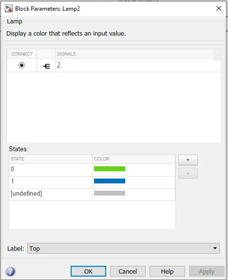
Connect all the displays and lamps respectively . change colour of lamp as follows;
0->green and 1->blue
RESULTS:
Gear 1:0-15kmph, in fig speed=6 kmph so g1 is turn into blue.display shows '1'.
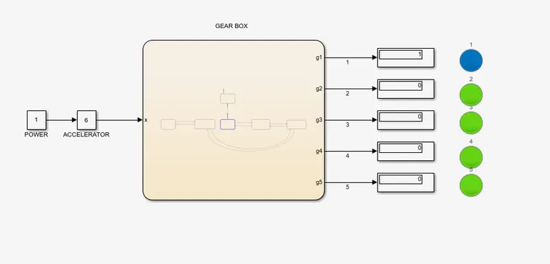
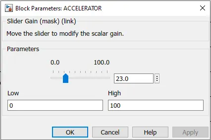
Gear 2:16-25kmph,using slider gain(Accelerator) we can change the speed (x) and here speed=23 kmph so g2 is glow blue.
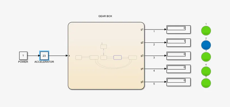
Gear 3:26-40kmph and in fig. speed=35 kmph so g3 will glow blue.
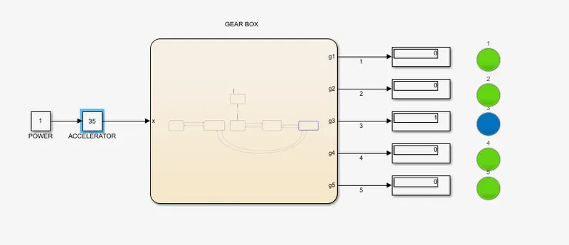
Gear 4:41-60kmph and speed =50 kmph so g4 glows blue.
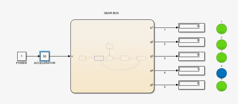
Gear 5:above 60 and speed or acceleartor in fig. is 100 kmph then g5 will glow.
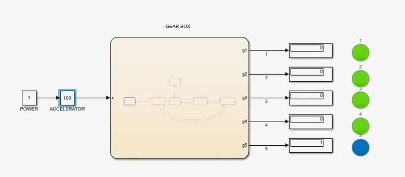
While slow downing when speed is 55 again the gear shift to the gear 4 g4 will glow.So while reversing or decreasing the speed same function will work .

CONSLUSION:
- Implemention is done successfully of control logic of a “washing machine” using Stateflow as per given sequence:
- If the power supply is available, the system gets activated
- If the Water supply is not available, stop the process & indicate through LED
- Soaking time should be 200s followed by Washing time of 100s.
- Then rinsing happens for next 20s & dryer runs for 50s
After all the processes have completed turn on the finished LED
2.Design of Simulink chart for the “Gear shift” logic as per below conditions:
Speed Range(kmph) Gear
0 to 15 1
16 to 25 2
26 to 40 3
41 to 60 4
Above 61 5
and display the speed input while the simulation is running & display the gear number is completed successively.