Project
AIM:
To study and observe the content of the main elements of ATV model with continously variable transmission(CVT) in open loop conditions and in closed loop conditions using lookup table.
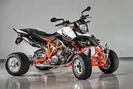
ATV vehicle
MAIN ELEMENTS:
- Signal builder
- Solver configuration
- Engine
- To and from
- simple gear
- RPM sensor
- PS-simulink converter
- PS terminator
- Input shaft inertia
- Variable ratio gear
- double shoe brake
- Vehicle body
- Tire
EXPLANATION & OBSERVATIONS:
ENGINE: It is a machine that uses the energy from liquid fuel or steam to produce the movement of the object.Heat engines are transform the heat into the movement through various thermodynamic process.Commonly used heat engines are Internal combustion engine.In the engine i.e; internal combustion chamber the fuel is injected in the chamber , ignition is on and the combustion is done causing the expand and drive the piston which produce the mechanical energy to the shaft.Emissions which are produce due to the combustion are released through th valves of the engine.
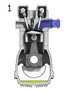
Animation showing the four stages of the four stroke gasoline combustion engine cycle:
- Induction (Fuel enters)
- Compression
- Ignition (Fuel is burnt)
- Emission (Exhaust out)
CONTINOUSLY VARIABLE TRANSMISSION:
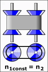
CVT is a automatic transmission that can change coherrently through a continuous range of gear ratios. This contrasts with other transmissions that provide a limited number of gear ratios in fixed steps. The flexibility of a CVT with suitable control may allow the engine to operate at a constant RPM while the vehicle moves at varying speeds.
Used in vehicles, tractors, motor scooters, snow automobiles, and earthmoving elements.
The most common type of CVT uses two pulleys connected by a belt or chain, however, several other designs have also been used at times.
SIMPLE GEAR BOX: A gearbox is a transmission device , used between engine’s output shaft and the final drive shaft seamlessly to transfer required torque and power to the wheels of automobile, a gearbox contains of the group of gears( i.e. spur, helical, bevel, worm and epicycle depending on the types of gearbox used )which are arranged in a special fashion to provide sepecfied gear or speed ratios to the final drive of the vehicle, a gearbox usually comes with the specification i.e.5-speed transmission with a reverse, and an automatic transmission.
single stage gear reducer.
VEHICLE BODY: It is the main supporting structure of a vehicle or automobile, to which all other components are attached. Truck uses a separate frame as chassis.
- SEDAN. A sedan has four doors and a traditional trunk. ...
- COUPE. Mercedes-Benz. ...
- SPORTS . These are the sportiest, hottest, coolest-looking coupes and convertibles—low to the ground, sleek, and often expensive. ...
- STATION WAGON. Volvo. ...
- HATCHBACK. ..
Simscape model of BAJA ATV model.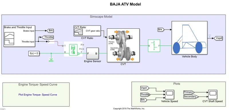
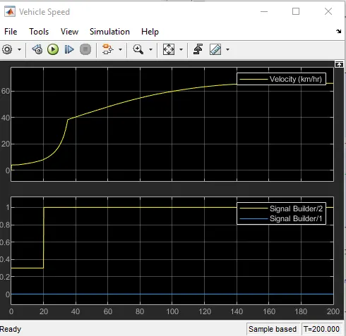
Here in this model , brake and throttle are inputs , the brake signal is constant and the throttle is suddenly changed at 20secs in the signal builder as shown in the figure below.
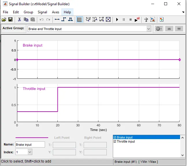
These input signals are connected to the input throttle signal piont"T".To observe the further responses of the vehicle parameters.
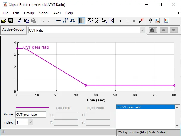
Second signal builder , CVT gear ratio signal is designed. and connected to the primary pulley of CVT.
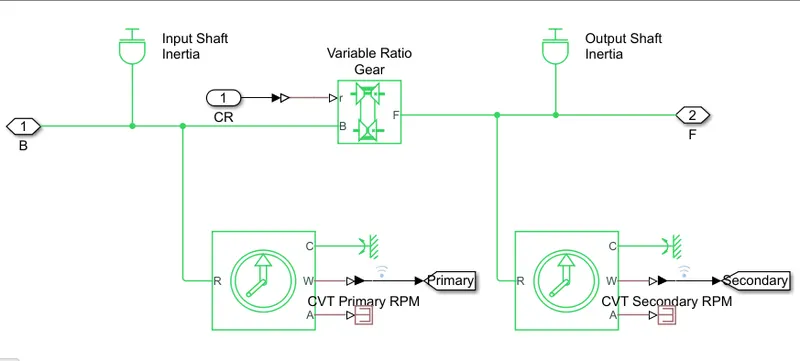
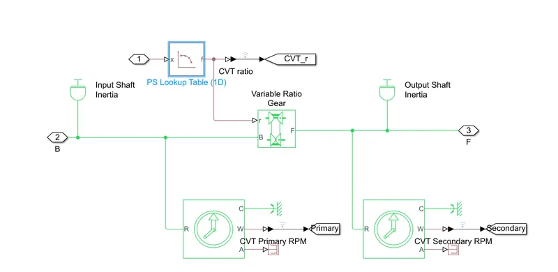
CVT subsystem : Input shaft inertia ,variable ratio gear and ideal rotational sensor are connected as shown in the fig.outputs can observe in sensors.
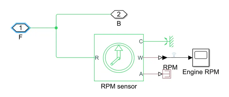
ENGINE SUBSYSTEM : engine is connected to the RPM sensor ,angular velocity 'W' port of the RPM is connected to the scope.
In the simple gear change the gear ratio to 12.further connect to the vehicle body .
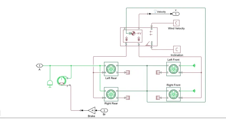
VEHICLE BODY SUBSYSTEM : In this submodel vehicle body is connected to four tires and dual shoe brake.
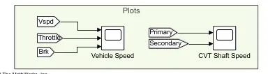
velocity,throttle and brake are connected to the one scope and CVT primary and secondary shafts outputs are connected to another scope.Using to-from blocks connected.
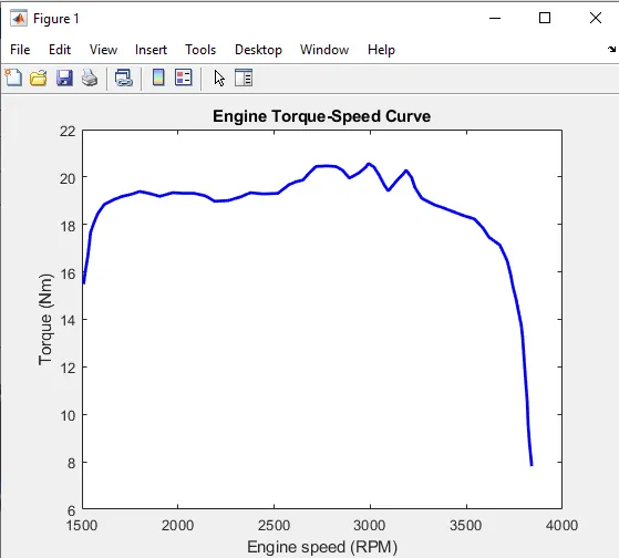
ENGINE TORQUE -SPEED CURVE data points are feeded to the engine by using GRABIT .
GRABIT is a file exchange file which can grap the data from any picture or graphical representation.
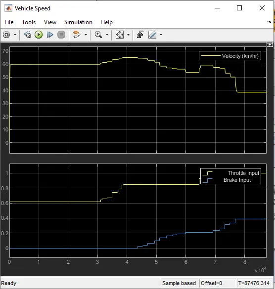
Resultant graph is shown below, the velocity is rapidly changed between the 20 -40 secs and further gradual increasing, throttle and brake are shown in the graph.signal of throttle is changed 0.3 to 1 and brake signal is constant.
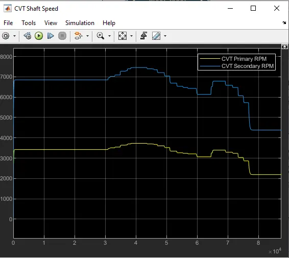
In this CVT primary pulley moves inside and secondary pulley moves outsides so radius of primary shaft is greater than secondary shaft.thus angular velocity of the secondary shaft is higher thar the primary shaft ., observed in the output graph.
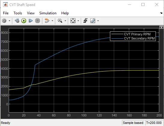
As a result secondary shaft is connected to the wheels shaft both velocity of vehicle and secondary pulley angular velocity graphs are same .
To the same model add few dashboard elements such as knob ,circular guage to the change inputs while through running the simulation.
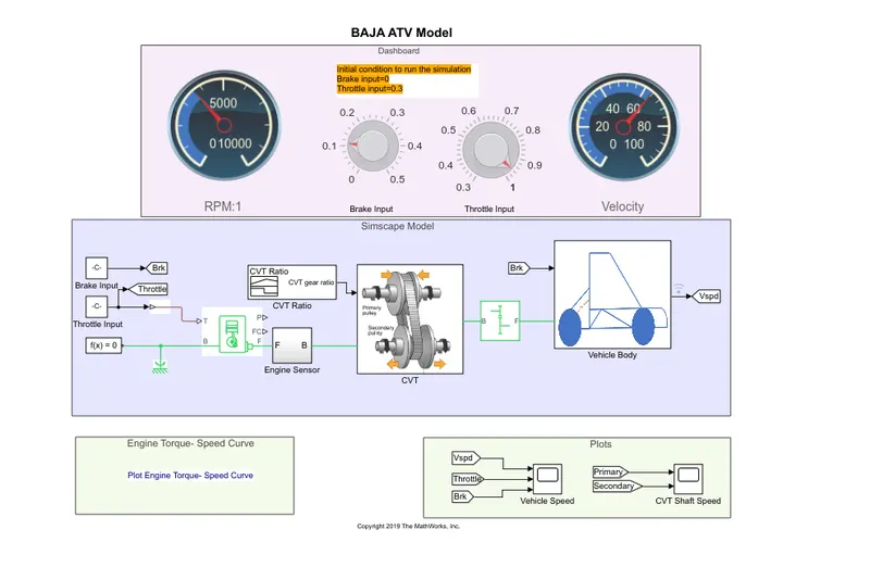
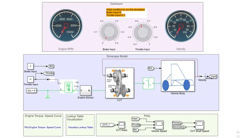
In the above model knobs are connected to the brake and throttle input. Circular guage are connected to the engine rpm and velocity of the vehicle.
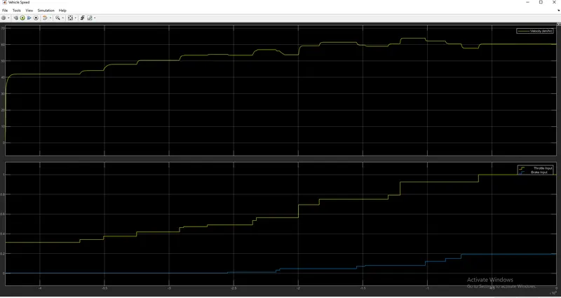
Hence the velocity resultant graph are shown in graphs while the throttle and brake signal graphs are changed with the help of knobs while runing the model is also shown in the below fig..
Angular velocities of the primary and secondary pulley results are shown in the fig.
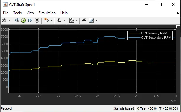
The two models are open loop model of ATV models and now we will observe and study about the closed loop models of the ATV model using lookup table. Lookup table connected between the velocity of the vehicle and primary shaft or pulley of CVT.In reality closed loop or feedback model of ATV models are used.
CLOSED LOOP MODE OF ATV MODEL
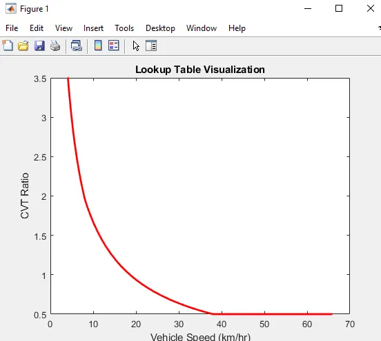
In the lookup table visualisation graph is plotted between velocity on X-axis and CVT ratio on Y-axis as shown in fig.
Angular velocities of the primary and secondary shafts of CVT and velocity Output graphs of the closed loop are shown below.
CONCLUSION:
Hence the study and conduct of the ATV model in open and closed loop are completed successively.