Week 7 - Simulation of a 1D Super-sonic nozzle flow simulation using Macormack Method
Aim:
We are going to simulate the isentropic flow through a quasi 1D subsonic-supersonic nozzle. You will derive both the conservation and non-conservation forms of the governing equations and solve them using the MacCormack's technique.
Objective:
We need to determine the steady-state temperature distribution for the flow-field variables and investigate the difference between the two forms of governing equations by comparing their solutions.
We need to show the following plots inside your report
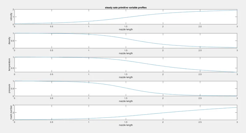
1. Steady-state distribution of primitive variables inside the nozzle
2. Time-wise variation of the primitive variables
3. Variation of Mass flow rate distribution inside the nozzle at different time steps during the time-marching process
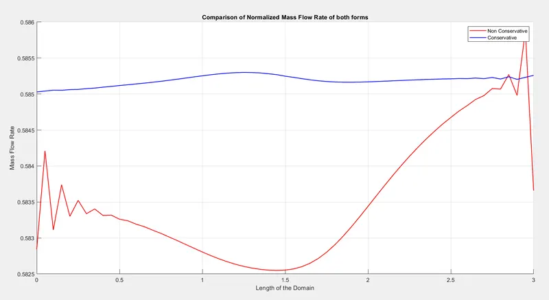
4. Comparison of Normalized mass flow rate distributions of both forms
Theory:
A CD Nozzle is a variable area passage which is used to accelerate gases to higher supersonic speeds. It consists of a converging section with minimum area occurring at a specific location called the throat.
Nozzles can be described as convergent (narrowing down from a wide diameter to a smaller diameter in the direction of the flow) or divergent (expanding from a smaller diameter to a larger one). A nozzle with a convergent section followed by a divergent section and is often called a convergent-divergent (CD) Nozzle.
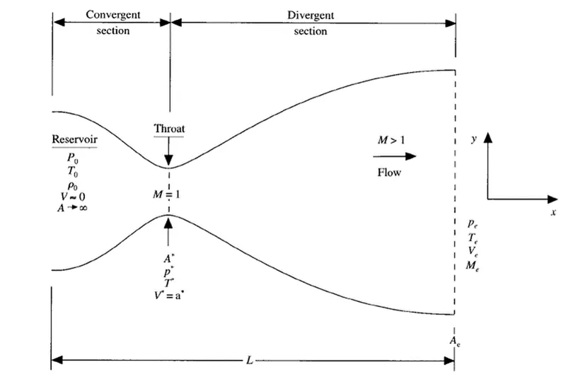
This image denotes 1D CD nozzle
what is quasi 1d:
Quasi one dimensional implies that we still have variations of flow quantities in one direction only but we allow the cross-section area of stream tubes to vary along the same direction as well. This means that we will be able to analyse axisymmetric channels with varying cross section areas such as for example convergent-divergent nozzles.
`(A/A^**)^2 = 1/M^2[2/(gamma+1)(1+(gamma-1)/2M^2)]^((gamma+1)/(gamma-1))`
where `gamma=(Cp)/(Cv)=1.4` for standard conditions of air
Here the equation for variation in pressure, density and temperature are given below.
`p/(p0)=(1+(gamma-1)/2M^2)^((-gamma)/((gamma-1))`
`rho/(rho0)=(1+(gamma-1)/2M^2)^((-1)/((gamma-1))`
`T/(T0)=(1+(gamma-1)/2M^2)^-1`
The quasi-one-dimensional assumption certain aspects of physics, we take the integral form of governing equations and work with them so that the physical aspects remain true. So, we can re-write the governing equations in following manner.
Governing equations:
Continuity equation: `(del(rhoA))/(delt)+rhoA(delV)/(delx)+rhoV(delA)/(delx)+VA(delrho)/(delx)=0`
Momentum equation: `rho(delV)/(delt)+rhoV(delV)/(delx)=-R(rho(delT)/(delx)+T(delrho)/(delx)`
Energy equation: `rhoc_v(delT)/(delt)+rhoVc_v(delT)/(delt)=-rhoRT[(delV)/(delx)+V(del(In A))/(delx)]`
Governing equation in conservative form:
Continuity equation: `(del(rho^'A^'))/(delt^')+(del(rho^'A^'V^'))/(delx^')`
Momentum equation: `(del(rho^'A^'V^'))/(delt^')+(del[rho^'A^'V^'2+(1/gamma)p^'A^'])/(delt^')=(1/gamma)p^'(delA^')/(delx^')`
Energy equation: `(del[rho^'(e^'/(gamma-1)+gamma/2V^'2)A^'])/(delt^')+(del[rho^'(e^'/(gamma-1)+gamma/2V^'2)V^'A^'+p^'A^'V^'])/(delx^')=0`
Governing equation non-conservative form:
Continuity equation: `(delrho^')/(delt^')=-rho^'(delV^')/(delx^')-rho^'V^'(rho(ln A^'))/(delx^')-V^'(delrho^')/(delx^')`
Momentum equation: `(delV^')/(delt^')=-V^'(delV^')/(delx^')-1/gamma((delT^')/(delx^')+T^'/rho^'(delrho^')/(delx^'))`
Energy equation: `(delT^')/(delt^')=-V^'(delT^')/(delx^')-(1-gamma)T^'[(delV^')/(delx^')+V^'(del(ln A^'))/(delx^')]`
Initial and boundary condition:
The characteristic line signifies the direction of information propagation across the boundary condition.
INLET BC : Subsonic region
RRC: Dirichlet
SD: Dirichlet
LRC: Neumann
OUTLET BC: Supersonic region
RRC : Neumann
SD: Neumann
LRC: Neumann
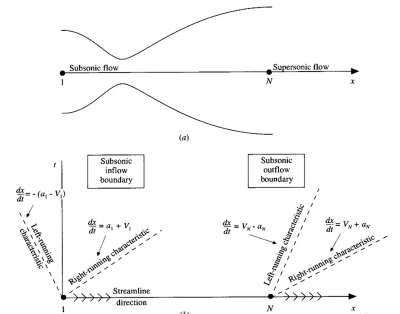
While we looking at the above diagram, we can easily observe that the inlet and outlet variables depend on time rate of change of velocities. Hence, we use Von-Neumann boundary conditions. In non-conservative form, we consider the following initial and boundary conditions initial condition.
`rho=1-0.3146x`
`T=1-0.2314x`
`V=(0.1+1.09x)T^(1/2)`
Above three values are initial condition at t=0
Boundary condtion inlet:
`V1=2V_2-V_3`
Outlet:
`V_n=2V_(N-1)-V_(N-2)`
`rho_N=2rho_(N-1)-rho_(N-2)`
`T_N=2T_(N-1)-T_(N-2)`
Conservative form in initial condition:
for `0<=x^'<=0.5`
`rho^'=1.0`
`T^'=1.0`
for `0.5<=x^'<=1.5`
`rho^'=1.0-0.366(x^'-0.5)`
`T^'=1.0-0.167(x^'-0.5)`
for`1.5<=x^'<=3.5`
`rho^'=0.634-0.3879(x^'-1.5)`
`T^'=0.833-0.3507(x^'-1.5)`
Inlet boundary condition:
`U_(1(i=1)=(rho^'A^')_(i=1)=(A^')_(i=1)= fixed value
`U_(2(i=1)=2U_(2(i=2))-U_(2(i=3)`
`U_3=U_1(T^'/(gamma-1)+gamma/2V^('2))`
Outlet:
`(U_1)_N=2(U_1)_(N-1)-(U_1)_(N-2)`
`(U_2)_N=2(U_2)_(N-1)-(U_2)_(N-2)`
`(U_3)_N=2(U_3)_(N-1)-(U3)_(N-2)`
here N=i
Discretization scheme:
By MacCormack Method,
`rho_(i,j)^(t+Deltat)=rho_(i,j)^t+((delrho)/(delt))_(av)Deltat`
here rho_(i,j)^(t+Deltat) is the density at next time step
and rho_(i,j)^t is the density at present time step
((delrho)/(delt))_(av) is the partial derivative of density obtained from predictor and corrector method
Deltat is the time step
Predictor step:
Below equation for density by replacing the partial difference with forward difference scheme,
`((delrho)/(delt))_(i,j)^t=-(rho_(i,j)^t(u_(i+1,j)^t-u_(i,j)^t)/(Deltax)+u_(i,j)^t(rho_(i+1,j)^t-rho_(i,j)^t)/(Deltax)+rho_(i,j)^t(v_(i,j+1)^t-rho_(i,j)^t)/(Deltay)+v_(i,j)^t(rho_(i,j+1)^t-rho_(i,j)^t)/(Deltay))`
Above the method is used to obtained the equation for predicted density, velocity and temperature at next time step
`rho_i^(-t+Deltat)=rho_i^t+((delrho)/(delt))_i^tDeltat`
`bar V_i^(t+Deltat)=V_i^t+((delV)/(delt))_i^tDeltat`
`barT_i^(t+Deltat)=T_i^t+((delT)/(delt))_i^tDeltat`
Corrector step:
Equation for density by replacing partial derivatives with rearward difference,
`(bar(delrho)/(delt))_i^(t+Deltat)=-rho_i^(-t+Deltat)(barV_i^(t+Deltat)-barV_(i-1)^(t+Deltat))/(Deltax)-rho_i^(-t+Deltat)barV_i^(t+Deltat)(ln A_i-ln A_(i-1))/(Deltax)-barV_i^(t+Deltat)(rho_i^(-t+Deltat)-rho_(i-1)^(-t+Deltat))/(Deltax)`
Similarly we can use temperature and velocity as well,
`(bar(delV)/(delt))_i^(t+Deltat)=-barV_i^(t+Deltat)(barV_i^(t+Deltat)-barV_(i-1)^(t+Deltat))/(Deltax)-1/gamma((barT_i^(t+Deltat)-barT_(i-1)^(t+Deltat))/(Deltax)+(barT_i^(t+Deltat))/(rho_i^(-t+Deltat))(rho_i^(-t+Deltat)-rho_(i-1)^(-t+Deltat))/(Deltax))`
`(bar(delT)/(delt))_i^(t+Deltat)=-barV_i^(t+Deltat)(barT_i^(t+Deltat)-barT_(i-1)^(t+Deltat))/(Deltax)-(gamma-1)barT_i^(t+Delta)xx(barV_i^(t+Deltat)-barV_(i-1)^(t+Deltat))/(Deltax)+barV_(i-1)^(t+Deltat)(ln A_i-ln A(i-1))/(Deltax)`
`((delrho)/(delt))_(av)=0.5[((delrho)/(delt))_i^t+(bar(delrho)/(delt))_i^(t+Deltat)]`
`((delV)/(delt))_(av)=0.5[((delV)/(delt))_i^t+(bar(delV)/(delt))_i^(t+Deltat)]`
`((delT)/(delt))_(av)=0.5[((delT)/(delt))_i^t+(bar(delT)/(delt))_i^(t+Deltat)]`
Equation for time step,,
`Deltat=C(Deltax)/(a+V)`
Code for non conservative:
clear all
close all
clc

% inputs
n = 31
x = linspace(0,3,n)
dx = x(2)-x(1);
gamma = 1.4;
th = round(n/2);

% calculate initial profile
rho = 1-0.3146*x;
t = 1-0.2314*x;
v = (0.1+1.09*x).*t.^0.5;

% area values
a = 1+2.2*(x-1.5).^2;
throat = find(a==1);


% courant number
c = 0.5;

% time step
nt = 1400;
dt = 0.01;

cfl = max((v+sqrt(t))*dt/dx);

% outer time loop
for k = 1:nt
    % time step control
    dt = min(c.*dx./(sqrt(t)+v));
    rho_old = rho;
    v_old = v;
    t_old = t;
    % predictor method
    for j = 2:n-1

        % drho_dt_p = -rho(j)*(v(j+1)-v(j)/dx-rho(j)*v(j)*(log(a(j+1)-log(a(j)))
        dvdx = (v(j+1)-v(j))/dx;
        drhodx = (rho(j+1)-rho(j))/dx;
        dtdx = (t(j+1)-t(j))/dx;
        dlogadx = (log(a(j+1))-log(a(j)))/dx;

        % continuity equation
        drhodt_p(j) = -rho(j)*dvdx - rho(j)*v(j)*dlogadx-v(j)*drhodx;

        % momentum equation
        dvdt_p(j) = -v(j)*dvdx -(1/gamma)*(dtdx+(t(j)/rho(j))*drhodx);

        % energy equation
        dtdt_p(j) = -v(j)*dtdx-(gamma-1)*t(j)*(dvdx+v(j)*dlogadx);

        % solution update
        rho(j) = rho(j) + drhodt_p(j)*dt;
        v(j) =v(j)+dvdt_p(j)*dt;
        t(j) = t(j)+dtdt_p(j)*dt;


    end

% corrector metho
for j = 2:n-1
        % drho_dt_p = -rho(j)*(v(j+1)-v(j)/dx-rho(j)*v(j)*(log(a(j+1)-log(a(j)))
        dvdx = (v(j)-v(j-1))/dx;
        drhodx = (rho(j)-rho(j-1))/dx;
        dtdx = (t(j)-t(j-1))/dx;
        dlogadx = (log(a(j))-log(a(j-1)))/dx;

        % continuity equation
        drhodt_c(j) = -rho(j)*dvdx - rho(j)*v(j)*dlogadx-v(j)*drhodx;

        % momentum equation
        dvdt_c(j) = -v(j)*dvdx -(1/gamma)*(dtdx+(t(j)/rho(j))*drhodx);

        % energy equation
        dtdt_c(j) = -v(j)*dtdx-(gamma-1)*t(j)*(dvdx+v(j)*dlogadx);


end

     % compute the average time derivative
     drhodt = 0.5*(drhodt_p+drhodt_c)
     dvdt = 0.5*(dvdt_p+dvdt_c)
     dtdt = 0.5*(dtdt_p+dtdt_c)

     % final solution update
     for i =2:n-1
         rho(i) = rho_old(i)+drhodt(i)*dt;
         v(i) = v_old(i)+dvdt(i)*dt;
         t(i) = t_old(i)+dtdt(i)*dt;

     end

     % apply the boundary condition
     % inlet boundary condition
     v(1) = 2*v(2)-v(3);

     % outlet boundary condition
     v(n) = 2*v(n-1)-v(n-2);
     rho(n) = 2*rho(n-1)-rho(n-2);
     t(n) = 2*t(n-1)-t(n-2);

     % mach nnumber
     M = v./(t.^0.5);
     % mass flow rate
     m = rho.*a.*v;
     % pressure
     p=rho.*t;

     figure(4)
     hold on
     if k == 1
         plot(x,m);
     end
     if k == 50
         plot(x,m);
     end
     if k == 250
         plot(x,m);
     end
     if k == 500
         plot(x,m);
     end
     if k == 750
         plot(x,m);
     end
     if k == 1400
         plot(x,m);
     end

     rho_throat(k) = rho(th);
     v_throat(k) = v(th);
     t_throat(k) = t(th);
     p_throat(k) = p(th);
     M_throat(k) = M(th);

end
     xlabel('nozzle length')
     ylabel('mass flow rate')
     legend('1dt','50dt','250dt','500dt','750dt','1200dt')
     title('variation of mass flow rate at different time step')


% plotting steady state mass flow rate changes
figure(1)
subplot(5,1,1)
plot(x,v)
xlabel('nozzle length')
ylabel('velocity')
title('steady sate primitive variable profiles')
subplot(5,1,2)
plot(x,rho)
xlabel('nozzle length')
ylabel('density')
subplot(5,1,3)
plot(x,t)
xlabel('nozzle length')
ylabel('temperature')
subplot(5,1,4)
plot(x,p)
xlabel('nozzle length')
ylabel('pressure')
subplot(5,1,5)
plot(x,M)
xlabel('nozzle length')
ylabel('mach number')

figure(2)
subplot(5,1,1)
plot(v_throat)
xlabel('time step')
ylabel('velocity')
title('Transient variation of primitive variable at throat')
subplot(5,1,2)
plot(rho_throat)
xlabel('time step')
ylabel('density')
subplot(5,1,3)
plot(t_throat)
xlabel('time step')
ylabel('temperature')
subplot(5,1,4)
plot(p_throat)
xlabel('time step')
ylabel('pressure')
subplot(5,1,5)
plot(M_throat)
xlabel('time step')
ylabel('mach number')

figure(3)
plot(x,m)
xlabel('nozzle length')
ylabel('Mass flow rate')
title('steady state mass flow rate')
Code explanation:
- First, we started the code with clear all, close all and clc to enable a fresh start without the manipulation of previous values.
- Next step is to give the input parameters are assigned for the variables x, dx, n, gamma, nt and C.
- In this code we have saw the Non-Conservative and Conservative forms are created as separate functions with the necessary inputs which is detailed below this section.
- Plotting is done for the following solutions
- Timestep variation at throat area of both forms
- Variation of Flow Rate Distribution of both forms
Code for conservative:
clear all
close all
clc

% inputs
n = 31;
x = linspace(0,3,n);
dx = x(2)-x(1);

gamma=1.4;
nt=1400;


% initial condition profile
for i = 1:length(x)
    if (x(i)<=0.5)
        rho(i) = 1;
        t(i) =1;


    elseif (x(i)>0.5 && x(i)<=1.5)
        rho(i) = 1-0.366*(x(i)-0.5);
        t(i) = 1-0.167*(x(i)-0.5);

elseif (x(i)>1.5) && (x(i)<=3.5)
        rho(i) = 0.634 - 0.3879*(x(i)-1.5);
        t(i) =  0.833-0.3507*(x(i)-1.5);
    end
end

% area values
a = 1+2.2*(x-1.5).^2;
throat = find(a==1);

%Initialization of solution variables
u1 = rho.*a;
u2 = 0.59*ones(1,n); % this is done to calculate velocity
v =u2/u1;
u3 = u1.*(t./(gamma-1)+(gamma/2).*v.^2);
M= v./(t.^0.5);        %mach number
m = rho.*a.*v;         %mass flow rate
p=rho.*t;   %pressure
%Courant Number
C = 0.5;
%Code structure
% outer time loop
for k =1:nt
    dt = min(C.*dx./(sqrt(t) + v));
    u1_old=u1;
    u2_old = u2;
    u3_old=u3;

    %Predictor step
    %Initialization flux
    for j =2:n-1
        f1=u2;
        f2 = ((u2.^2)./u1) + (((gamma-1)/gamma)*(u3-(gamma/2)*((u2.^2)./u1)));
        f3 = (gamma*(u2.*u3)./u1) - ((gamma*(gamma-1)/2)*((u2.^3)./(u1.^2)));
        %Source term
        j_p = (1/gamma)*rho(j)*t(j)*((a(j+1)-a(j))/dx);
        %Continuity equation
        du1dt_p(j) = -(f1(j+1)-f1(j))./dx;

        %Momentum Equation
        du2dt_p(j) = -(f2(j+1)-f2(j))./dx +j_p;

        %Energy equation
        du3dt_p(j) = -(f3(j+1)-f3(j))./dx;

         %Solution update
         u1(j) =u1_old(j)+du1dt_p(j)*dt;
         u2(j) = u2_old(j)+du2dt_p(j)*dt;
         u3(j)= u3_old(j)+du3dt_p(j)*dt;

         %Updating solution variables
         rho = u1./a;
         v = u2./u1;
         t = (gamma-1).*(u3./u1-(gamma/2).*(v).^2);
    end


% corrector method
for j = 2:n-1
          f1=u2;
          f2 = ((u2.^2)./u1) + (((gamma-1)/gamma)*(u3-(gamma/2)*((u2.^2)./u1)));
          f3 = (gamma*(u2.*u3)./u1) - ((gamma*(gamma-1)/2)*((u2.^3)./(u1.^2)));

      % continuity equation
        du1dt_c(j) = -(f1(j)-f1(j-1))/dx;

        J_c = (1/gamma)*rho(j)*t(j)*(a(j)-a(j-1))/dx;

        % momentum equation
        du2dt_c(j) = -(f2(j)-f2(j-1))/dx+J_c;

        % energy equation
        du3dt_c(j) = -(f3(j)-f3(j-1))/dx;

 end

     % compute the average time derivative
     du1dt = 0.5*(du1dt_p+du1dt_c);
     du2dt = 0.5*(du2dt_p+du2dt_c);
     du3dt = 0.5*(du3dt_p+du3dt_c);

     % final solution update
     for s =2:n-1
         u1(s) = u1_old(s)+du1dt(s)*dt;
         u2(s) = u2_old(s)+du2dt(s)*dt;
         u3(s) = u3_old(s)+du3dt(s)*dt;

     end


     % inlet boundary
     u1(1) = a(1);
     u2(1) = 2*u2(2) -u2(3);
     u3(1) = u1(1)*(t(1)/(gamma-1)+(gamma*v(1)^2)/2);

     % outlet boundary condition
     u1(n) = 2*u1(n-1)-u1(n-2);
     u2(n) = 2*u2(n-1)-u2(n-2);
     u3(n) = 2*u3(n-1)-u3(n-2);

     % final update
     rho = u1./a;
     t = (gamma-1)*(u3./u1 -(gamma/2)*(u2./u1).^2);
     v = u2./u1;
     p = rho.*t;
     M= v./t.^0.5;
     error(i) =  abs(v(i)-v(i-1));

     % mass flow rate
     m = u2;

     rho_th(k) = rho(throat);
     v_th(k) = v(throat);
     t_th(k) = t(throat);
     p_th(k) = p(throat);
     M_th(k) = M(throat);


     figure(4)
     hold on
     if k == 1
         plot(x,m);

     elseif k == 50
         plot(x,m);

     elseif k == 250
         plot(x,m);

     elseif k == 500
         plot(x,m);

     elseif k == 750
         plot(x,m);

     elseif k == 1400
         plot(x,m);
     end

end
     xlabel('nozzle length')
     ylabel('mass flow rate')
     legend('1dt','50dt','250dt','500dt','750dt','1200dt')
     title('variation of mass flow rate at different time step')


% plotting steady state mass flow rate changes
figure(1)
subplot(5,1,1)
plot(x,v)
xlabel('nozzle length')
ylabel('velocity')
title('steady sate primitive variable profiles')
subplot(5,1,2)
plot(x,rho)
xlabel('nozzle length')
ylabel('density')
subplot(5,1,3)
plot(x,t)
xlabel('nozzle length')
ylabel('temperature')
subplot(5,1,4)
plot(x,p)
xlabel('nozzle length')
ylabel('pressure')
subplot(5,1,5)
plot(x,M)
xlabel('nozzle length')
ylabel('mach number')

figure(2)
subplot(5,1,1)
plot(v_th)
xlabel('time step')
ylabel('velocity')
title('Transient variation of primitive variable at throat')
subplot(5,1,2)
plot(rho_th)
xlabel('time step')
ylabel('density')
subplot(5,1,3)
plot(t_th)
xlabel('time step')
ylabel('temperature')
subplot(5,1,4)
plot(p_th)
xlabel('time step')
ylabel('pressure')
subplot(5,1,5)
plot(M_th)
xlabel('time step')
ylabel('mach number')
Explanation:
- The function is used to calculate the values of Mass flow rate, Pressure, Mach number, Density, velocity, Temperature, Density at throat, velocity at throat, Temperature at throat, Mass flow rate at throat, Pressure at throat, Mach number at throat by the known equations for all the grid points.
- In this code we have use for this initial boundary conditions are established for Density, Temperature & Velocity and profiles for calculating area & throat. Now Outer Time loop is computed for for loop to calculate all the grid points for various formulas inside the loop.
- In this code we are using MacCormack technique this method is used to solve the numerical solution of governing equations such as Continuity, Momentum & Energy Equation.
- This technique implies two methods for solving namely Predictor method followed by Corrector method.
- We are using Predictor & Corrector method are assigned within the for loop individually for calculating values.
- Next, we calculated the values are averaged in the next step and updating the solution with old values.
- In this method we are using Boundary Conditions are applied within the for loop and subsequently used for calculating the Mass Flow Rate, Mach Number & Pressure and also calculating the values throat section.
- Finally, plotting is done for Distance(x) & Mass Flow Rate for different Timesteps.
Code for Comparison of normalized flow rate:
clear all
close all
clc

%Inputs
n=61;
x = linspace(0,3,n);
dx =x(2)-x(1);
gamma =1.4;
nt=1400;
% dt=0.01;

%Calculate initial profiles

rho_nc = 1-0.3146*x; %density
t_nc = 1-0.2314*x;   %Temperature
v_nc = (0.1+1.09*x).*t_nc.^0.5; %Velocity
for s=1:length(x)
    if (x(s)<=0.5)
        rho_c(s) = 1;
        t_c(s) = 1;
    elseif (x(s)>0.5) && (x(s)<=1.5)
        rho_c(s) = 1-0.366*(x(s)-0.5);
        t_c(s)= 1-0.167*(x(s)-0.5);
    elseif (x(s)>1.5) && (x(s)<=3.5)
        rho_c(s) = 0.634-0.3879*(x(s)-1.5);
        t_c(s)= 0.833-0.3507*(x(s)-1.5);
    end
end

a  = 1+2.2*(x-1.5).^2; %area
throat = find(a==1);
M_nc= v_nc./(t_nc.^0.5);        %mach number
        %mass flow rate
p_nc=rho_nc.*t_nc;                %pressure
%Initialization of solution variables
u1 = rho_c.*a;
u2 = 0.59*ones(1,n); % this is done to calculate velocity
v_c =u2/u1;
u3 = u1.*(t_c./(gamma-1)+(gamma/2).*v_c.^2);
M_c= v_c./(t_c.^0.5);        %mach number
m_c = rho_c.*a.*v_c;         %mass flow rate
p_c=rho_c.*t_c;   %pressure
%Courant Number
C = 0.5;

%Code structure
%time steps

%Outer time loop
for k =1:nt
    %Time-step control
    dt = min(C.*dx./(sqrt(t_nc) + v_nc));
    rho_old=rho_nc;
    v_old = v_nc;
    t_old=t_nc;
    u1_old=u1;
    u2_old = u2;
    u3_old=u3;

    %Predictor step

    for j =2:n-1
        %drho_dt_p = -rho(j)*(v(j+1)-v(j))/dx -rho(j)*v(j)*(log(a(j+1))-log(a(j)))/dx-v(j)*(rho(j+1)-rho(j))/dx;
        dvdx =(v_nc(j+1)-v_nc(j))/dx;
        drhodx = (rho_nc(j+1)-rho_nc(j))/dx;
        dtdx = (t_nc(j+1)-t_nc(j))/dx;
        dlogadx = (log(a(j+1))-log(a(j)))/dx;
        f1=u2;
        f2 = ((u2.^2)./u1) + (((gamma-1)/gamma)*(u3-(gamma/2)*((u2.^2)./u1)));
        f3 = (gamma*(u2.*u3)./u1) - ((gamma*(gamma-1)/2)*((u2.^3)./(u1.^2)));
        %Source term
        j_p = (1/gamma)*rho_c(j)*t_c(j)*((a(j+1)-a(j))/dx);

        %Continuity equation
        drhodt_p(j) = -rho_nc(j)*dvdx -rho_nc(j)*v_nc(j)*dlogadx-v_nc(j)*drhodx;
        du1dt_p(j) = -(f1(j+1)-f1(j))./dx;

        %Momentum Equation
        dvdt_p(j) = -v_nc(j)*dvdx -(1/gamma)*(dtdx+(t_nc(j)/rho_nc(j))*drhodx);
        du2dt_p(j) = -(f2(j+1)-f2(j))./dx +j_p;

        %Energy equation
        dtdt_p(j) = -v_nc(j)*dtdx-(gamma-1)*t_nc(j)*(dvdx+v_nc(j)*dlogadx);
        du3dt_p(j) = -(f3(j+1)-f3(j))./dx;

%         %Solution update
         rho_nc(j) =rho_nc(j)+drhodt_p(j)*dt;
         v_nc(j) = v_nc(j)+dvdt_p(j)*dt;
         t_nc(j)= t_nc(j)+dtdt_p(j)*dt;
         u1(j) =u1_old(j)+du1dt_p(j)*dt;
         u2(j) = u2_old(j)+du2dt_p(j)*dt;
         u3(j)= u3_old(j)+du3dt_p(j)*dt;

         %Updating solution variables
         rho_c = u1./a;
         v_c = u2./u1;
         t_c = (gamma-1).*(u3./u1-(gamma/2).*(v_c).^2);
    end


       %Corrector method using backward differencing
       for j =2:n-1
        %drho_dt_p = -rho(j)*(v(j)-v(j-1))/dx -rho(j)*v(j)*(log(a(j))-log(a(j-1)))/dx-v(j)*(rho(j)-rho(j-1))/dx;
        dvdx =(v_nc(j)-v_nc(j-1))/dx;
        drhodx = (rho_nc(j)-rho_nc(j-1))/dx;
        dtdx = (t_nc(j)-t_nc(j-1))/dx;
        dlogadx = (log(a(j))-log(a(j-1)))/dx;
          f1=u2;
          f2 = ((u2.^2)./u1) + (((gamma-1)/gamma)*(u3-(gamma/2)*((u2.^2)./u1)));
          f3 = (gamma*(u2.*u3)./u1) - ((gamma*(gamma-1)/2)*((u2.^3)./(u1.^2)));
        %Source term
        j_c = (1/gamma)*rho_c(j)*t_c(j)*((a(j)-a(j-1))/dx);

        %Continuity equation
        drhodt_c(j) = -rho_nc(j)*dvdx -rho_nc(j)*v_nc(j)*dlogadx-v_nc(j)*drhodx;
        du1dt_c(j) = -(f1(j)-f1(j-1))./dx;
        %Momentum Equation
        dvdt_c(j) = -v_nc(j)*dvdx -(1/gamma)*(dtdx+(t_nc(j)/rho_nc(j))*drhodx);
        du2dt_c(j) = -(f2(j)-f2(j-1))./dx +j_c;
        %Energy equation
        dtdt_c(j) = -v_nc(j)*dtdx-(gamma-1)*t_nc(j)*(dvdx+v_nc(j)*dlogadx);
        du3dt_c(j) = -(f3(j)-f3(j-1))./dx;
         %Solution update is not required

        end
      %Compute the average time derivative

      drhodt_nc=0.5*(drhodt_p+drhodt_c);
      dvdt_nc=0.5*(dvdt_p+dvdt_c);
      dtdt_nc=0.5*(dtdt_p+dtdt_c);
      du1dt=0.5*(du1dt_p+du1dt_c);
      du2dt=0.5*(du2dt_p+du2dt_c);
      du3dt=0.5*(du3dt_p+du3dt_c);

      %Final solution update
      for i=2:n-1
         rho_nc(i) =rho_old(i)+drhodt_nc(i)*dt;
         v_nc(i) = v_old(i)+dvdt_nc(i)*dt;
         t_nc(i)= t_old(i)+dtdt_nc(i)*dt;
          u1(i) =u1_old(i)+du1dt(i)*dt;
         u2(i) = u2_old(i)+du2dt(i)*dt;
         u3(i)= u3_old(i)+du3dt(i)*dt;
      end

      %Apply boundary conditions
      %Inlet
      v_nc(1) = 2*v_nc(2)-v_nc(3);
      u1(1) = a(1);
        u2(1) = 2*u2(2)-u2(3);
        u3(1) = u1(1)*(t_c(1)/(gamma-1) + (gamma*(u2(1)/u1(1))^2)/2);

      %Outlet
      rho_nc(n)= 2*rho_nc(n-1)-rho_nc(n-2);
      v_nc(n)= 2*v_nc(n-1)-v_nc(n-2);
      t_nc(n)= 2*t_nc(n-1)-t_nc(n-2);
       u1(n)= 2*u1(n-1)-u1(n-2);
         u2(n)= 2*u2(n-1)-u2(n-2);
         u3(n)= 2*u3(n-1)-u3(n-2);

      m_nc = rho_nc.*a.*v_nc;

      rho_c = u1./a;
        v_c = u2./u1;
        t_c=(gamma-1).*(u3./u1-(gamma/2).*(u2./u1).^2);
        p_c = rho_c.*t_c;
        M_c= v_c./t_c.^0.5;
        error(i) =  abs(v_c(i)-v_c(i-1));
        m_c= u2;

     %Calculating Variables at throat section
    rho_th_nc(k) =  rho_nc(throat);
    t_th_nc(k) =    t_nc(throat);
    v_th_nc(k) =   v_nc(throat);
    m_th_nc(k) =   m_nc(throat);
    P_th_nc(k) =   p_nc(throat);
    M_th_nc(k) =    M_nc(throat);

     rho_th_c(k) =  rho_c(throat);
    t_th_c(k) =    t_c(throat);
    v_th_c(k) =   v_c(throat);
    m_th_c(k) = m_c(throat);
    P_th_c(k) = p_c(throat);
    M_th_c(k) =    M_c(throat);


end

%Plotting the comparison between normalized flow rate of both forms
figure(1)
hold on
plot(x,m_nc,'r','linewidth',1.25)
hold on;
plot(x,m_c,'b','linewidth',1.25)
hold on;
grid on

legend('Non Conservative','Conservative');
xlabel('Length of the Domain')
ylabel('Mass Flow Rate')
title('Comparison of Normalized Mass Flow Rate of both forms')
Code explanation:
This function is used to calculate the values of Mass flow rate, Pressure, Mach number, Density, velocity, Temperature, Density at throat, velocity at throat, Temperature at throat, Mass flow rate at throat, Pressure at throat, Mach number at throat by the known equations for all the grid points.
In this code we have use for this initial boundary conditions are established for Density, Temperature & Velocity and profiles for calculating area & throat. Now Outer Time loop is computed for for loop to calculate all the grid points for various formulas inside the loop.
In this code we are using MacCormack technique this method is used to solve the numerical solution of governing equations such as Continuity, Momentum & Energy Equation.
This technique implies two methods for solving namely Predictor method followed by Corrector method.
Comparison of Normalized Mass Flow Rate of both forms Each plot is computed as subplots of four primitive variables such as Density, Temperature, Pressure and Mach Number at throat as well as Convergent/Divergent section.
Non conservative steady state plot:
Conservative steady state plot:
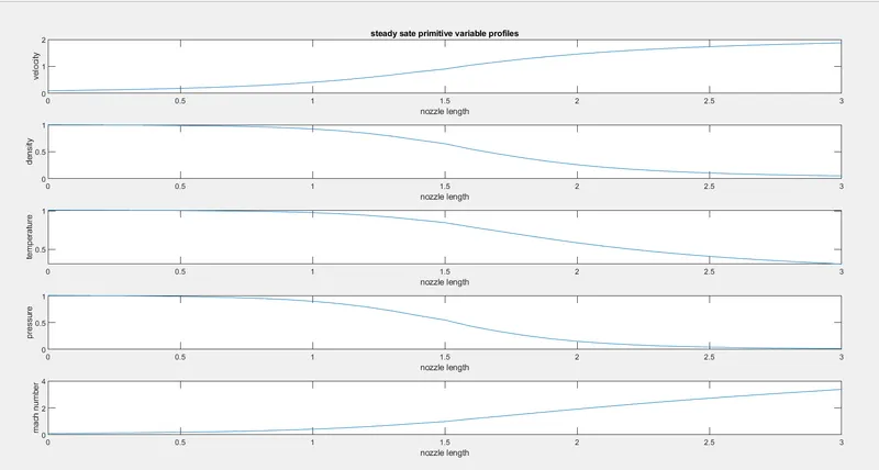
Above the plots are denotes we can conclude that initial variations observed in Non-Conservative form for a certain period of time makes it consume higher amount of time to achieve stable solution when compared to Conservative form.
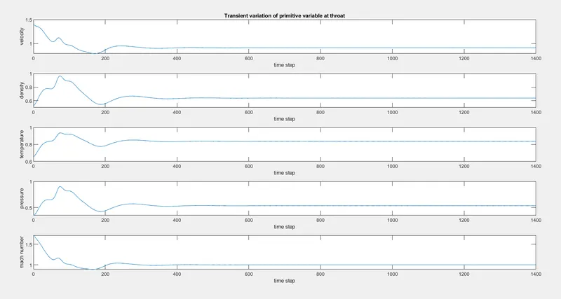
Non-conservative transient variation of primitive variable plot:
conservative transient variation of primitive variable plot:
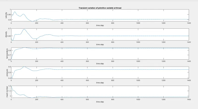
Here we are going to observing the above plots we could see that both the forms are in same phase giving the exact same solution for all the values.
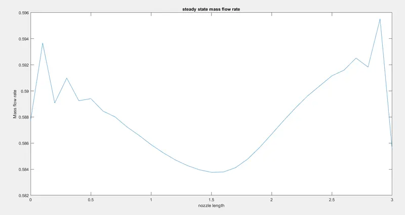
Non conservative steady state mass flow rate plot:
Conservative variation of mass flow rate at different time steps plot:
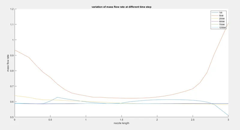
Non-Conservative variation of mass flow rate at different time steps plot:
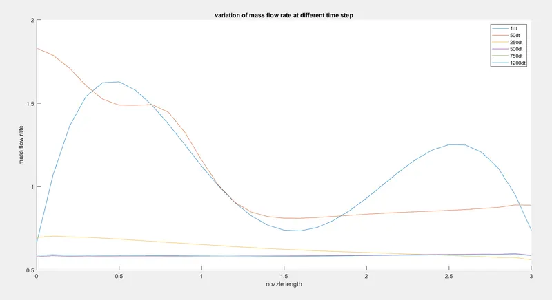
Above the plots are shows that Mass Flow Rate at different Time steps along the Distance oscillates initially, however the solution becomes stable after the timestep for both the forms attaining a constant value.
Comparision of normalized mass flow rate for both conservative and non-conservative plot:
Results:
The final solution of both the forms are almost similar, the non-Conservative form oscillates much when compared to Conservative form. The latter also gives almost stable solution along the length.
This plot we can conclude that Conservative form attains stability in lesser number of iterations with earliest time.
Conclusion:
Finally, we conclude all the above results we can evidently conclude that Conservative form converges slightly faster than non-conservative form offering stable solution along the simulation. Yet both the forms are dependable in calculating the solutions which is almost precise.
The conservation form yields a better mass flow distribution or conservation of mass. We can observe this from the mass flow rate Vs Time step graph or Mass flow rate vs distance graph, where the results seem to be more consistent for conservative form.
The Non-conservative form leads to a smaller residual. Non-conservative form does a better job in the sense that residual decay is an index of quality of numerical algorithm.
Next the Non-conservative form seems to produce slightly more accurate results for primitive variables and conservative form seems to produce more accurate results for flux variables. The results in either case are satisfactory. Finally, the Conservative form requires more calculation time due to decoding of primitive variables to flux variables