Week 7: Shock tube simulation project
Aim --> Shock tube simulation project
Theory
The shock tube is an instrument used to replicate and direct blast waves at a sensor or a model in order to simulate actual explosions and their effects, usually on a smaller scale. Shock tubes (and related impulse facilities such as shock tunnels, expansion tubes, and expansion tunnels) can also be used to study aerodynamic flow under a wide range of temperatures and pressures that are difficult to obtain in other types of testing facilities. Shock tubes are also used to investigate compressible flow phenomena and gas-phase combustion reactions.
A shock wave inside a shock tube may be generated by a small explosion (blast-driven) or by the buildup of high pressures which cause diaphragm(s) to burst and a shock wave to propagate down the shock tube (compressed-gas driven).
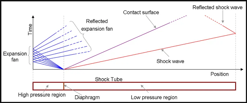
A simple shock tube is a tube, rectangular or circular in cross-section, usually constructed of metal, in which gas at low pressure and gas at high pressure is separated using some form of a diaphragm. The diaphragm suddenly bursts open under predetermined conditions to produce a wave propagating through the low-pressure section. The shock that eventually forms increases the temperature and pressure of the test gas and induces a flow in the direction of the shock wave.
The low-pressure gas, referred to as the driven gas, is subjected to the shock wave. The high-pressure gas is known as the driver gas. The corresponding sections of the tube are likewise called the driver and driven sections. The driver gas is usually chosen to have a low molecular weight, (e.g., helium or hydrogen) for safety reasons, with a high speed of sound, but maybe slightly diluted to 'tailor' interface conditions across the shock. To obtain the strongest shocks the pressure of the driven gas is well below atmospheric pressure (a partial vacuum is induced in the driven section before detonation).
The bursting diaphragm produces a series of pressure waves, each increasing the speed of sound behind them so that they compress into a shock propagating through the driven gas. This shock wave increases the temperature and pressure of the driven gas and induces a flow in the direction of the shock wave but at a lower velocity than the lead wave. Simultaneously, a rarefaction wave, often referred to as the Prandtl-Meyer wave, travels back into the driver gas.
The interface, across which a limited degree of mixing occurs, separates driven and driver gases are referred to as the contact surface and follow, at a lower velocity, the lead wave.
Applications
- In addition to measurements of rates of chemical kinetics shock tubes have been used to measure dissociation energies and molecular relaxation rates.
- They have been used in aerodynamic tests. The fluid flow in the driven gas can be used much as a wind tunnel, allowing higher temperatures and pressures therein to replicate conditions in the turbine sections of jet engines.
- They have been further developed into shock tunnels, with an added nozzle and dump tank. The resultant high-temperature hypersonic flow can be used to simulate atmospheric re-entry of spacecraft or hypersonic craft, again with limited testing times.
- Results from shock tube experiments can be used to develop and validate a numerical model of the response of a material or object to an ambient blast wave without flying debris.
- Shock tubes are also used in biomedical research to find out how biological tissues are affected by blast waves.
Geometry
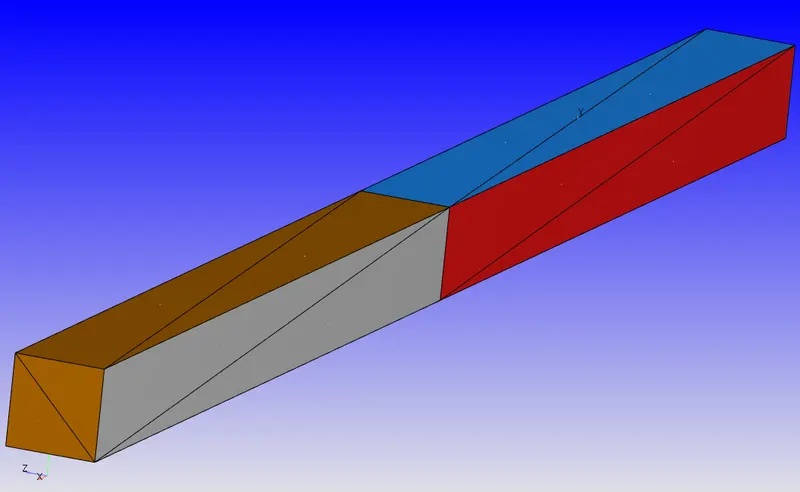
Normals (Normals must point inside the geometry)
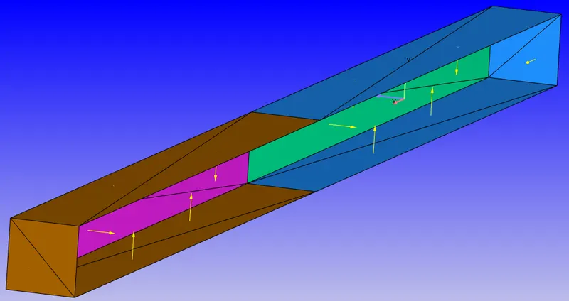
Diagnosis test

Boundaries
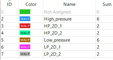
Case-Setup
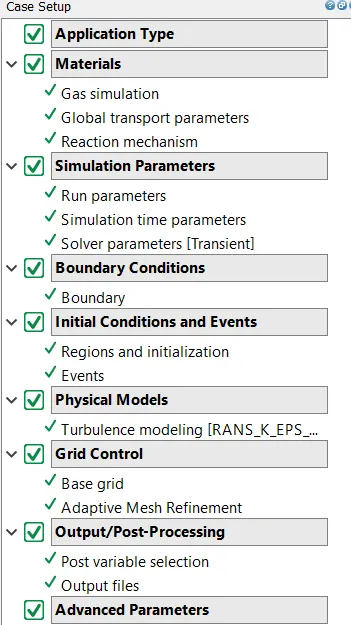
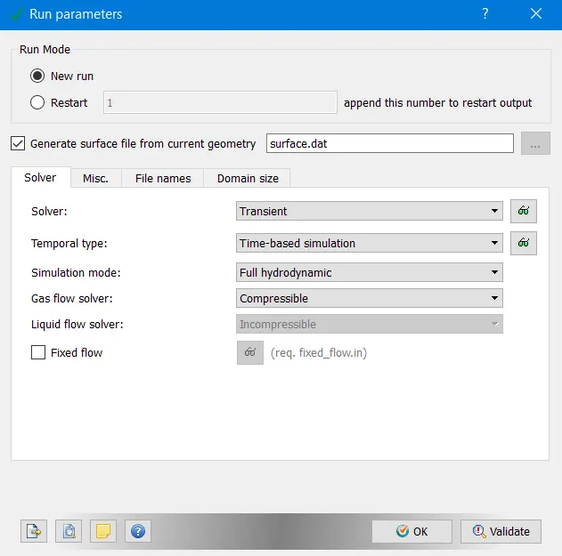
- Transient Solver
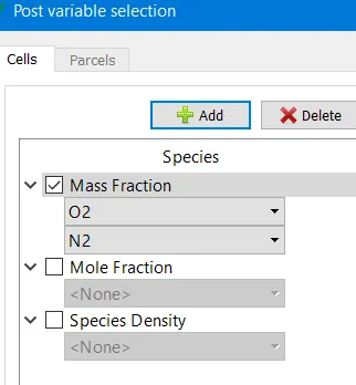
- Species --> Nitrogen(N2) and Oxygen(O2)
- Run parameters
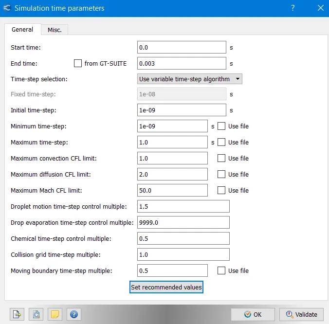
- Time period --> 0.003 seconds.
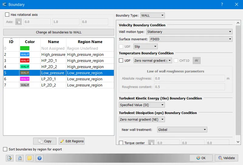
- Boundary Conditions
- High-pressure region
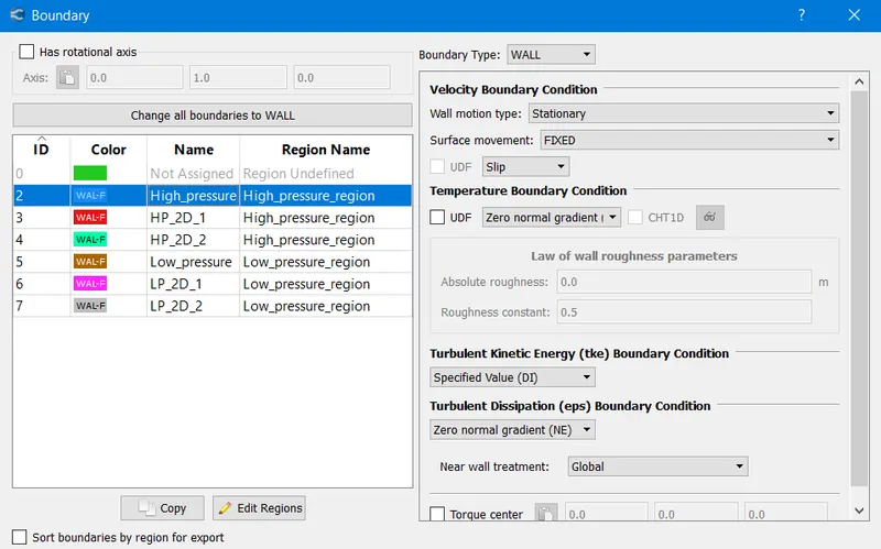
- Low-pressure region
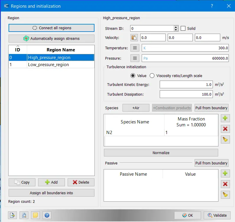
- Regions and Initialization
- High-pressure region (contains N2 Nitrogen at 6 bar pressure)
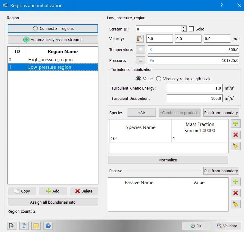
- Low-pressure region (contains O2 Oxygen at 1 bar pressure)
- There is no inlet and outlet all boundaries are slip walls.
- The 2 pressure regions are connected and disconnected by using events.
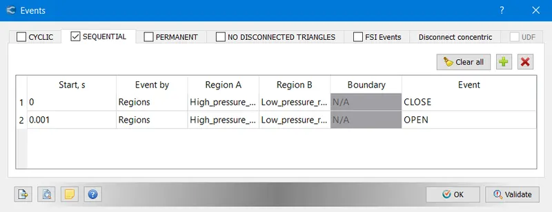
- After 0.001 seconds the 2 pressure regions are connected.
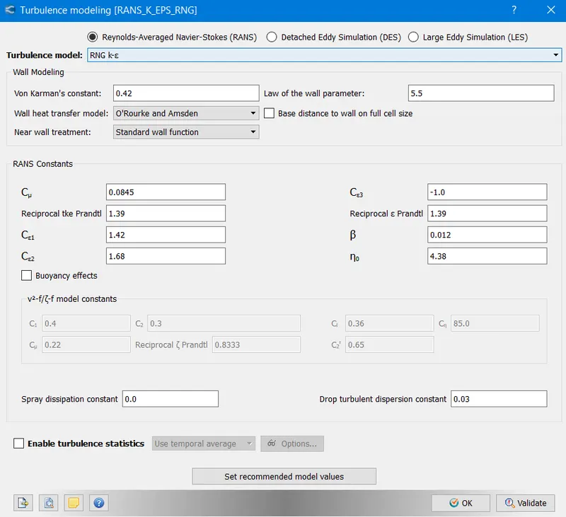
- Turbulence model K-e RNG model.
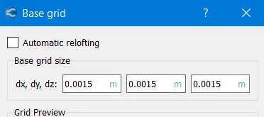
- Base grid
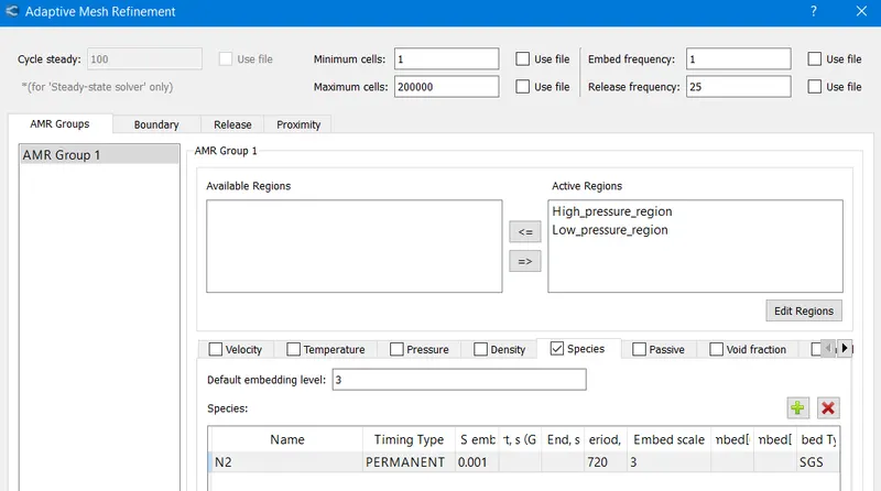
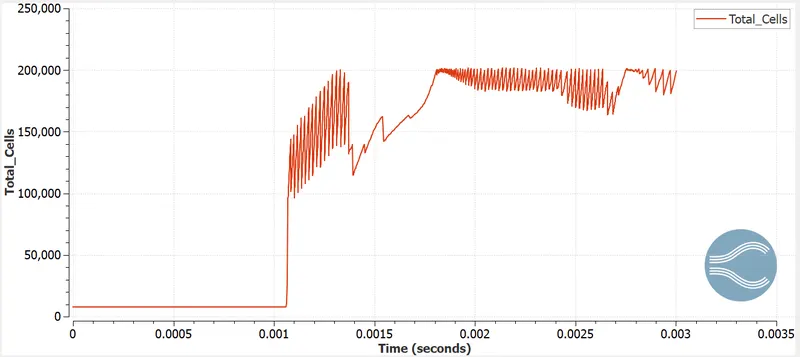
- Adaptive Mesh refinement (N2 species refinement)
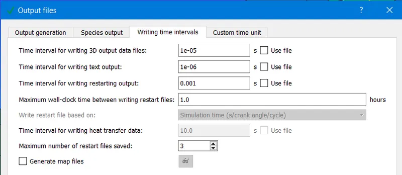
- Output files
- Post-processing variables
Results
- Mesh (AMR)
- Mass-fraction of Nitrogen N2
- Velocity
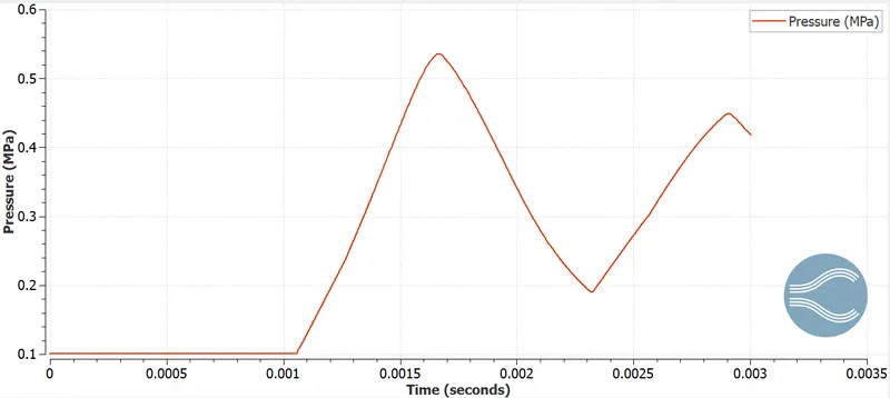
- Pressure
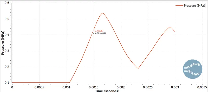
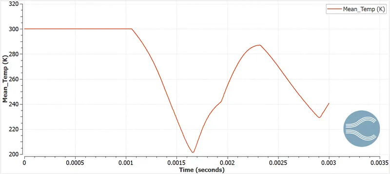
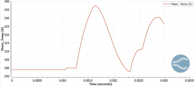
- Temperature
- High-pressure region
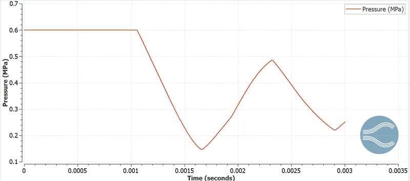
- Low-pressure region
Conclusion
- Shock-tube was successfully simulated, learnt and the working principle examined.
- We also learnt the purpose of the concept of events.