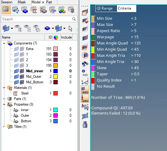
Week 7- Meshing of Backdoor Challenge
AIM
Meshing Backdoor Geometry of the car
OBJECTIVE
To mesh the given backdoor geometry of an automobile using the manual midsurfacing procedure. must make sure the mesh is of the finest quality, has a small amount of trias, and flows well.
PROCEDURE
1. We must choose one of the parts and remove its midsurface in order to mesh the part component by component. This will have to be done manually. In the beginning, a new component is made and given the name "Mid of X"—X being the component on which we will be focusing.
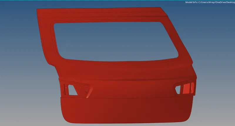
2. Next, we may measure the component's thickness before it is midsurfaced. which in this instance is 0.75 mm. For manually creating the midsurface, we require this. And the offset tool found in surface edit is used to do this.
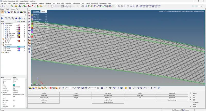
3. Half of the thickness must be measured for the offset tool. which in this instance would be 0.375 mm. Any face from among the faces can be chosen. After that is done, right-click surfaces and choose "by face." The full face is chosen once this is done. not the whole element.
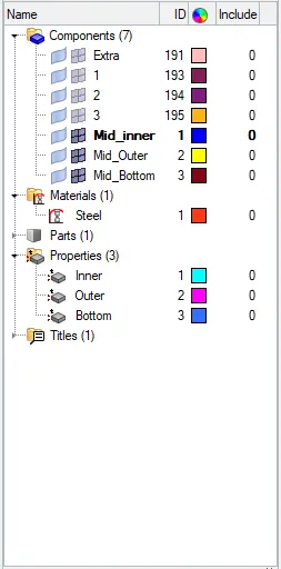
4. We must confirm that the newly produced midsurface component is our current component before moving on to the next step. We may choose "duplicate" by choosing surfaces once more after confirming. We may now choose "current component." Now, the component's offset gets passed to the component we just made. Yet, we have not yet offset the face.
5. We may check the forthcoming offset's normal, which can be in the other direction, before clicking the offset button. If so, we may reorient it in the other way by choosing the "reverse normal" option. We may then click offset after that. We have now produced our midsurface onto the just built component.
6. Due to the size of these components and their symmetry about the centre, we may work on half of each component and reflect it afterwards to simplify the meshing procedure. You may accomplish this by choosing half of the component and utilising the delete option. If necessary, we might have to use the rapid edit section's split surface option.
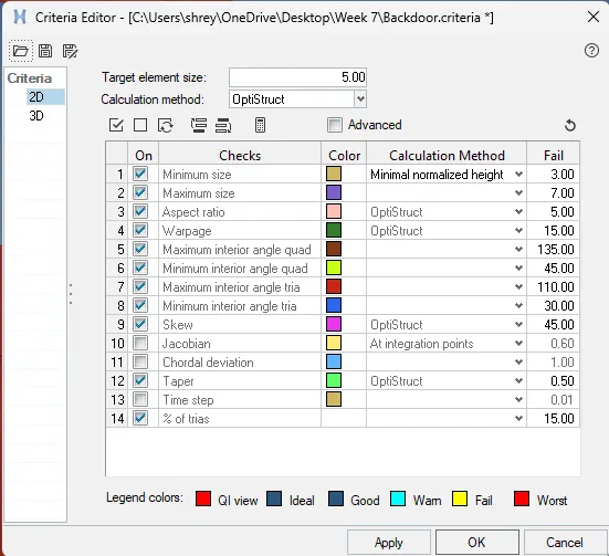
7. i. As with meshing in general, we should begin meshing in a specific place and work our way outward from there (preferably one with more free edges). In order to improve mesh control, we may utilise cut lines to separate the surface into smaller surfaces (quick edit > split surface node).
ii. In order to ensure that the surfaces we design do not promote tria formation, we also need to toggle lines that might obstruct mesh flow and apply our best judgement (like pointed edges).
iii. Using a variety of tools, we may clean the mesh once it has been constructed. We will mostly use the drag tria tool, element optimise tool, and to a lesser extent, the swap edge tool. They may be accessible using the 2D menu's quality index section.
iv. Once we've finished meshing and cleaning up one surface, we may go on to the next. Up till the component is fully mesh, the operation is repeated.
8. To generate the other symmetrical half, we must utilise the reflect tool because the component has been cut in two. Go to the tools menu to find the reflect tool. We must first decide which factors to reflect. As both halves could not be perfectly symmetrical, be careful not to choose areas that are not otherwise a part of the other half. After that, we may choose the base point and the axis on which we are reflecting. Following that, we must duplicate by right-clicking "elements" in the reflect toolbar. We may then click reflect after that. This will result in the current component's mirrored half being created.
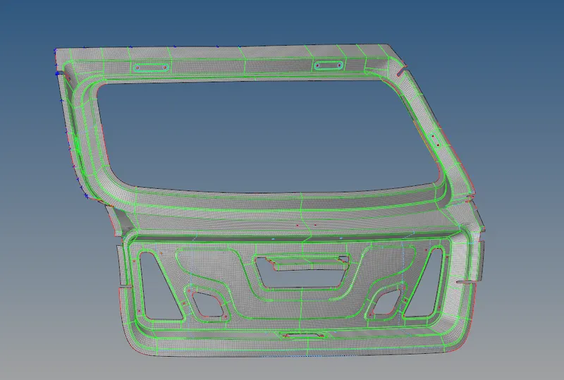
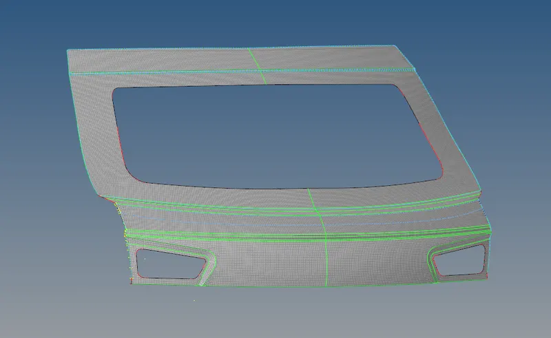
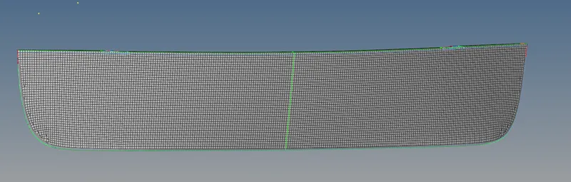
9. We will now preview equivalence for various tolerances in the tools menu's edges section to verify for equivalent (ranging between 0.2 mm to 2 mm). This is to make sure there are no open edges or misaligned elements, both of which we can verify by selecting a different option from the same area. We may inspect the nodes that need equivalence using the preview equivalence option. By selecting the "equivalence" option from the menu, they are fixed. It could be necessary to manually correct it using the replace node option if some nodes haven't been taken care of (F3).
10. After equivalence, we can use the check elements tool in the same menu to look for duplication. If there are duplicates, we may choose "save failed," go to the tool menu, choose "delete," choose the elements, right-click the elements, choose "retrieve," and then choose "delete." The duplicates should be handled by this.
11. We may now give each of our midsurfaces a thickness. They are of the same size (0.75 mm). Right-clicking and adding a component in the component tree will let us accomplish this. Once a property is formed, we can apply the aforementioned thickness by going to its section at the bottom left and scrolling down. After choosing the midsurface, heading to its properties box on the bottom left, and assigning a prop id by selecting the thickness property, we may then assign the thickness. In a similar manner, we may allocate the material using the same procedure.
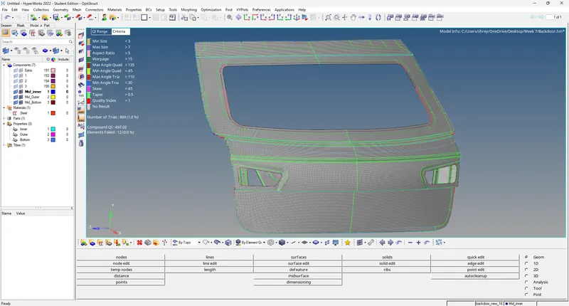
RESULTST
The geometry has been manually midusrfaced and meshes with the highest quality and mesh flow. The proper thickness was assigned to the mesh. The file has also been cleared of elements that did not contribute to the final mesh.