Simulation of Motion of Long Piston With Cam Using Ansys Workbench
OBJECTIVE
- To assign the structural steel material to the cam, follower, and barrel.
- To assign the frictionless and frictional contact according to the case.
- To assign the joints.
- To mesh the model.
- To apply the boundary condition.
- To collect the results and interpret.
PROCEDURE
This simulation was a cam-follower analysis of the sphere. The cam-follower model can be seen in the figure below. The simulation seems to be transient-structural, therefore, it had to solve using the transient-structural module of Ansys. The simulation was solved with three different cases. In the first case, the behavior of contact between faces was kept frictionless, in the second, it was changed to frictional with a value coefficient of friction of 0.1, and in the third, the value of the coefficient of friction was changed to 0.2.
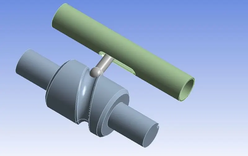
Figure 1: Cam-follower model in Ansys GUI.
The Mesh section of the Static Structural module was opened. In that, the material of all the parts was set to structural steel (default).
Further, the Ansys automatically detected the contacting faces and created contact cards for them with bonded behavior. This bonded behavior was changed to frictionless for the first case, and frictional for the second and the third case.
A revolute joint was defined for the cam, and a translational joint was defined for the follower. The barrel was fixed to its position.
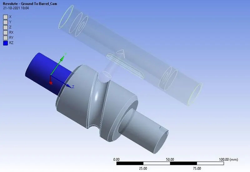
Figure 2: Revolute joint for the cam.
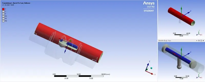
Figure 3: Translational joint for the follower.
Next, the mesh was created for the model, as shown in the figure below.
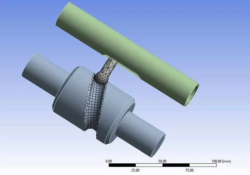
Figure 4: Meshing of the model.
The analysis was solved in 9 steps. In boundary condition, the rotation was applied to the cam in 9 steps, as shown in the figure.
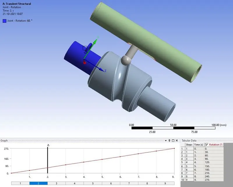
Figure 5: Rotation applied to the cam.
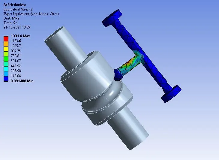
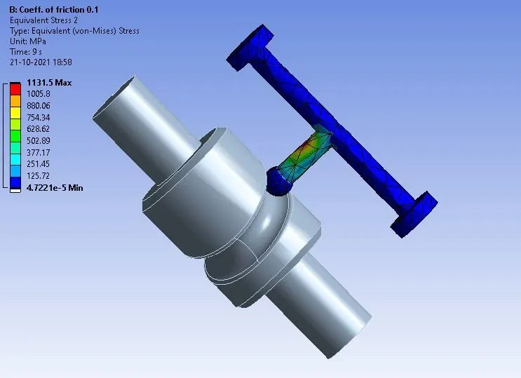
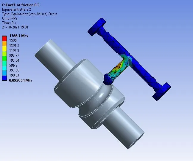
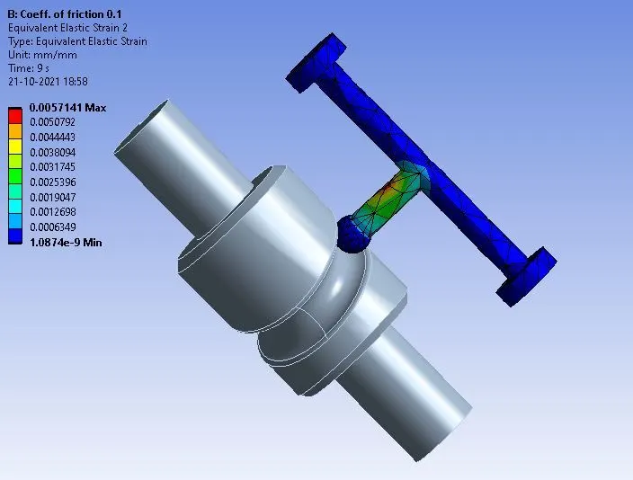
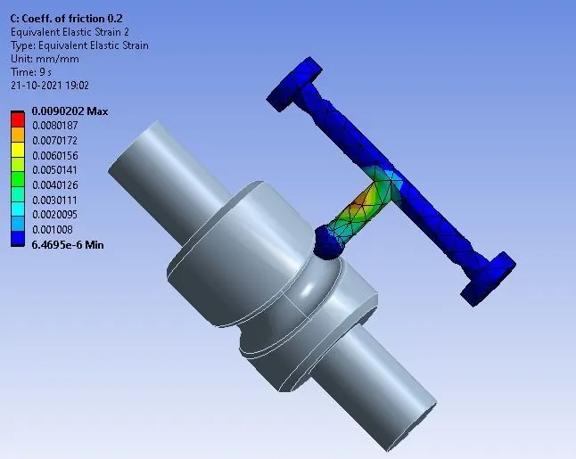
In the solution, the results were requested for the equivalent stress, directional deformation, and equivalent strain. All the results are shown in the figures below.
|
|
|
|
|
Maximum equivalent stress = 1331.6 MPa |
Maximum equivalent stress = 1131.5 MPa |
Maximum equivalent stress = 1788.7 MPa |
|
Figure 6: Equivalent stress developed in the model |
||
|
|
|
|
|
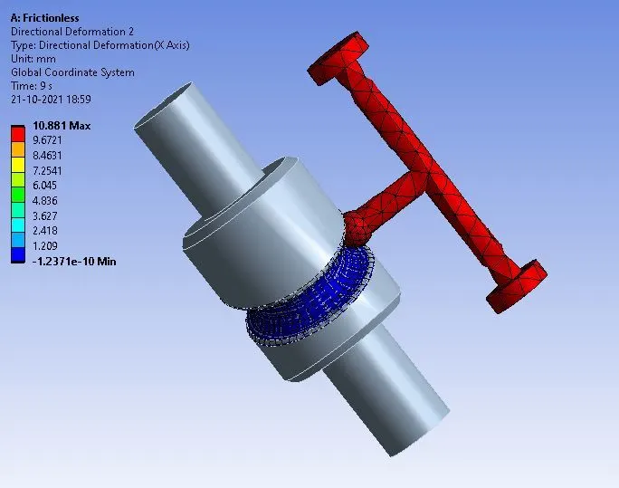
Maximum directional deformation = 10.881 mm |
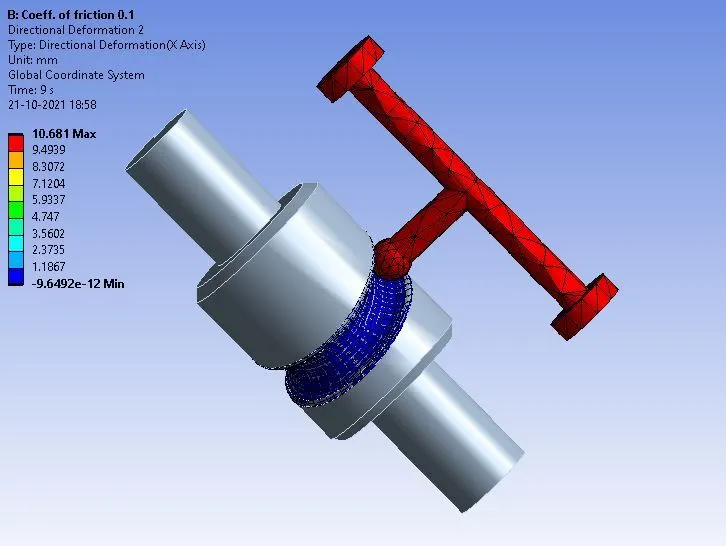
Maximum directional deformation = 10.681 mm |
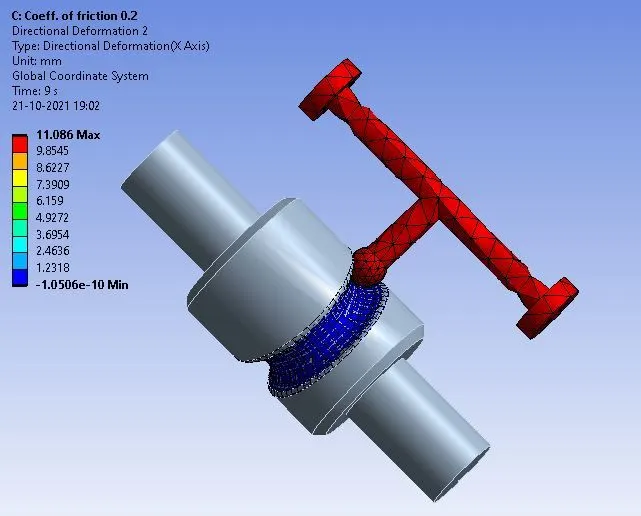
Maximum directional deformation = 11.086 mm |
|
Figure 7: Maximum directional deformation in the model |
||
|
|
|
|
|
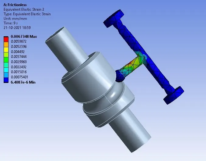
Maximum equivalent elastic strain = 0.0067 mm/mm |
Maximum equivalent elastic strain = 0.0057 mm/mm |
Maximum equivalent elastic strain = 0.0090 mm/mm |
|
Figure 8: Equivalent elastic strain developed in the model |
||
CONCLUSION
In this work, a cam-follower motion was analyzed using three different cases. In the first case, the behavior of contact between faces was set to frictionless, in the second, it was set to frictional with the value of the coefficient of friction equal to 0.1, and in the third, the value was increased to 0.2. As a result, there is not much difference in the stress-induced in case 1 and case 2. But in case 3, there is a significant increase in the value of stress. This is, obviously, due to the increase in the value of the coefficient of friction, which led to increasing in frictional force. And due to the increase in stress, the increase in the strain value can be seen in the results.