Week 7-Long Piston With Cam
OBJECTIVE
To perform transient analysis on a Piston and Cam mechanism model with three different contacts as mentioned in the below cases
Case 1: Frictionless contact
Case 2: Frictional contact with 0.1 as the Friction Co-efficient
Case 3: Frictional contact with 0.2 as the Friction Co-efficient
Compare the results of Equivalent Stress, Directional Deformation and Equivalent Elastic Strain and provide conclusion
Case setup
- After opening ANSYS Workbench, we are met with the Project Schematic window. Here, we can select the 'Transient Structural' analysis system on the left. Doing so creates a new project. Here, we can rename the project and also change the material if needed. We will need to right-click 'Geometry' and select 'import'. The file provided for this project should be selected.
- To create/edit new materias go to engineering data sources - general materials - select required materials.
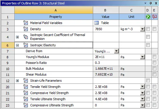
- For this project we used ony structural steel material for all 3 cases
Material properties of structural steel
- The 3D model of the setup is imported into ANSYS Space Claim. Check for any abnormalities in the Geometry.
MODEL SETUP:
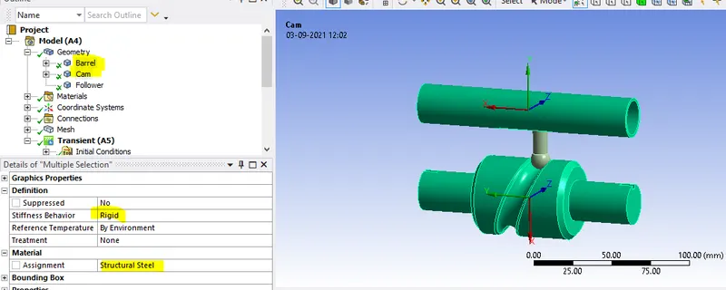
After importing the Geometry, rename the components as Barrel , cam and follower and assign structural steel as material.
For the Barrel and the Cam, the Stiffness behaviour is assigned as Rigid.
CONTACTS DEFINITION:
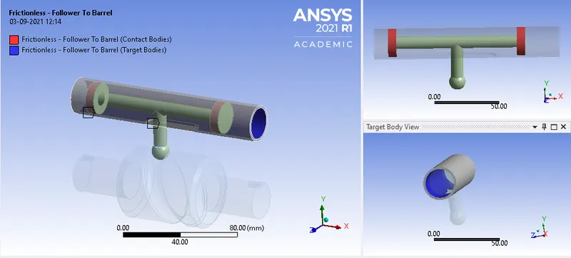
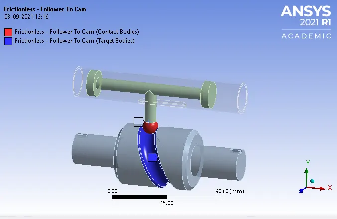
We need to define two contact regions for this model. The contact regions are selected between the barrel and the follower & between follower and Cam.
JOINT DEFINITION:
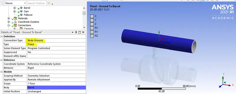
- A fixed support for the barrel
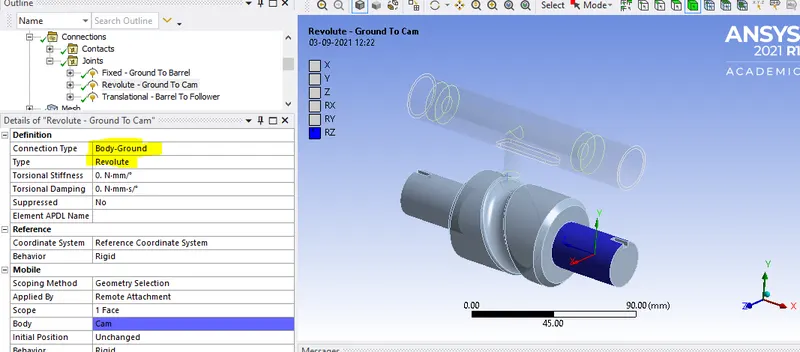
- A Revolute joint is assigned for the Cam, Make sure the reference co-ordinate system assigned to the joint is along the Z axis.
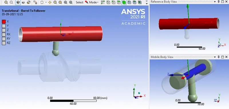
- A Translational Body-Body joint is assigned to the follower relative to the barrel,Make sure the reference co-ordinate system assigned to the joint is along the X axis.
MESHING:
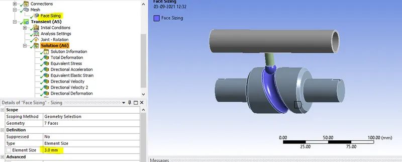
- Generated a default mesh for total setup , we refine the mesh contact surfaces of follower and cam using face sizing option with an element size of 3mm and turn off the adaptive sizing option.
MESH QUALITY
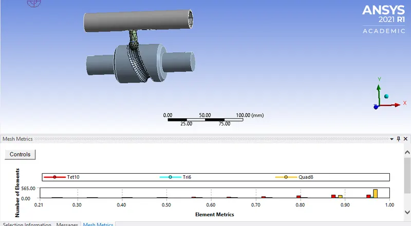
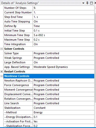
ANALYSIS SETTINGS:
For analysis settings we use total 9 steps for the 1st step the settings are
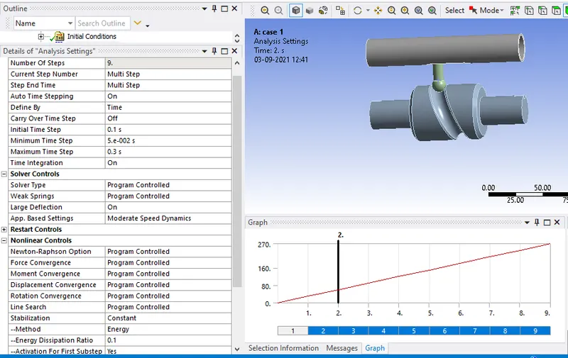
For steps 2 to 9
BOUNDARY CONDITIONS:
A Revolute Joint load is assigned to the Cam:
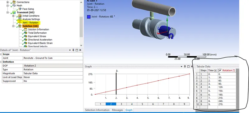
Now we can generate the outputs. To do this, Solution > Insert > Strain > Equivalent (Von-Mises) (for equivalent strain) and right-click Solution > Insert > Stress > Equivalent (Von-Mises) (for stress). right-click Solution > Insert > defrmation > directional deformation (X-axis)
RESULTS
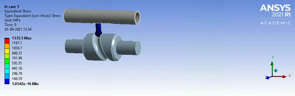
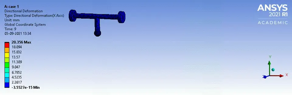
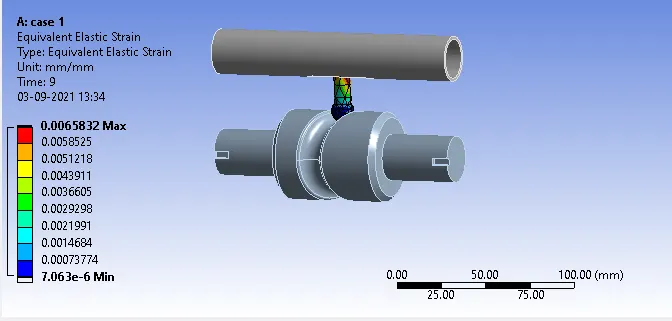
Case 1: Frictionless contact
Equivalent Stress
Directional Deformation
Equivalent Elastic Strain
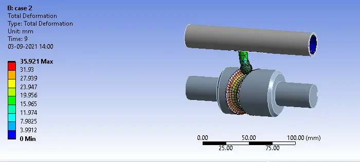
Total deformation
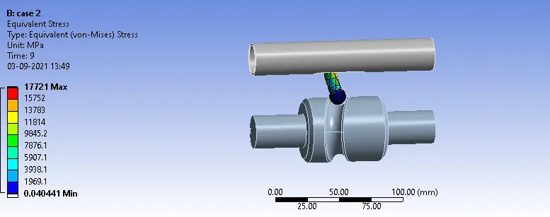
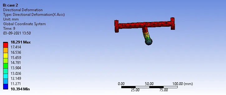
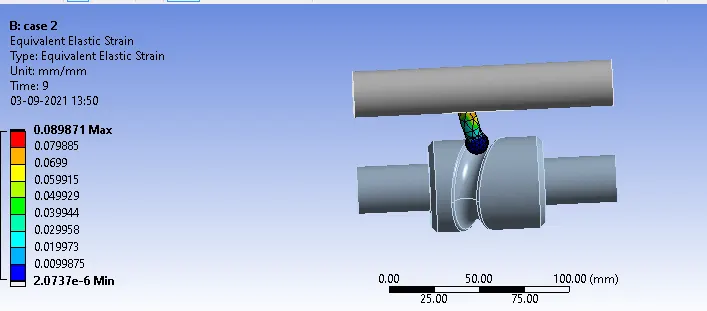
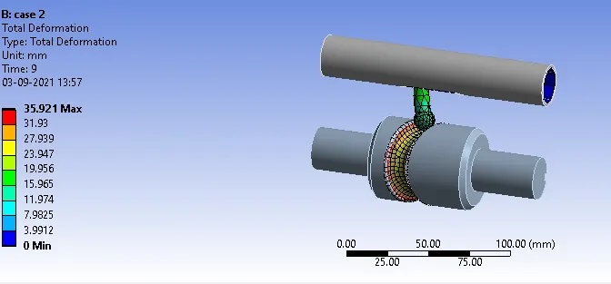
Case 2: Frictional contact with 0.1 as the Friction Co-efficient for the Contact regions
Equivalent Stress
Directional Deformation
Equivalent Elastic Strain
Total deformation
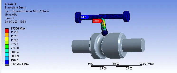
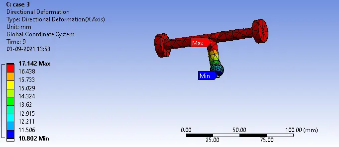
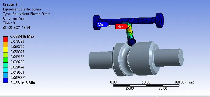
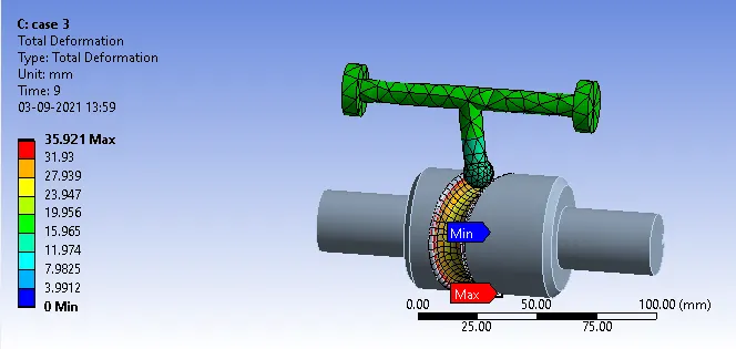
Case 3: Frictional contact with 0.2 as the Friction Co-efficient for the Contact regions
Equivalent Stress
Directional Deformation
Equivalent Elastic Strain
Total deformation
CONCLUSION:
From the above results we can see that as the frictional co-efficient increases the equivalent stress, strain and Directional deformation increases. As there is friction the energy required also increases hence the stress and strain also increases. Total deformation remains constant for all three cases.
More force is required to over come the friction and force is directly proportional to stress thus the stress increases. Stress is directly proportional to strain and thus strain increases.
Google link
https://drive.google.com/file/d/12JjX4fL0Tczi7_iDIrjFOQ4oSGfLgksw/view?usp=sharing