Week 9-Creation of 1D Connectors Challenge
Aim :- To Create connector and Attach the various parts of the given model and Mesh the given Component with a Mesh size of 5mm.
1. Right_Rail_2 & Front_truss_1:- Seam-Quad(angled+capped+L)
2. Left_Rail_2 & Front_truss_1:- Quad elements
3. Front_truss_2, Front_truss_1 & Right_Rail_1:- Spot weld with 3 Layers and 5 mm Diameter
4. Front_truss_2, Front_truss_1 & Left_Rail_1:- Hexa (Adhesive)
5. Rear_truss_2 & Right_Rail_2:- Bolt Connector
6. Rear_truss_2 & Left_Rail_2:- Bolt Connector
7. Right_Rail_1 & Right_Rail_2:- Spot-weld with Rigid Elements
8. Left_Rail_1 & Left_Rail_2:- Spot-weld with Spring Elements
9. Rest all the component left Join them with suitable connectors
Procedure :-
- Import the given .hm file into hypermesh , go to import model- select model - cick on import
- There are 9 components in assembly, Mesh the each components with given element size of 5mm.
- For meshing go to 2D- AUTOMESH - select type of element - give element length - cick on mesh.
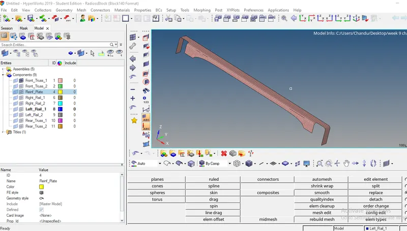
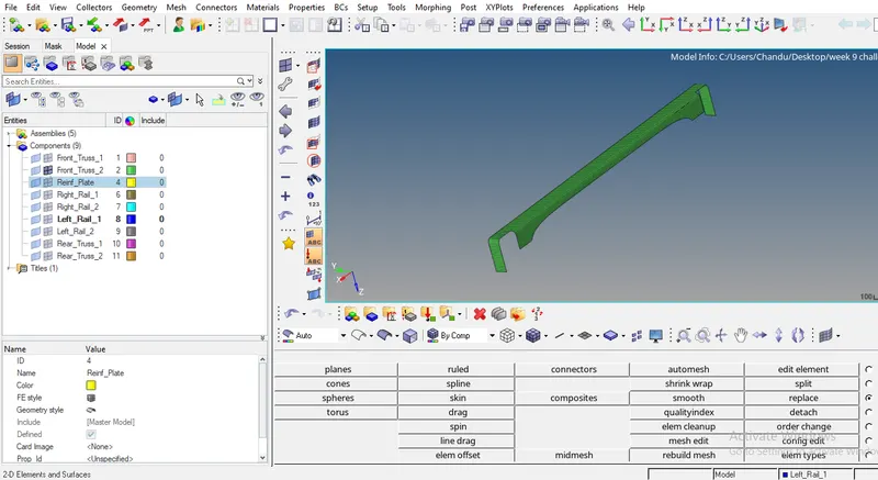
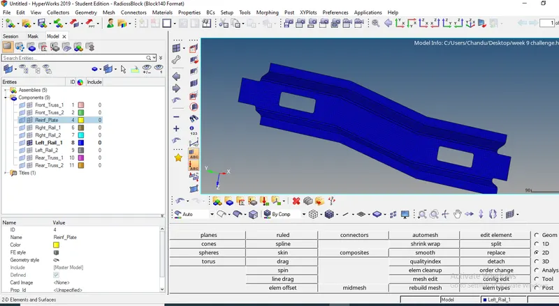
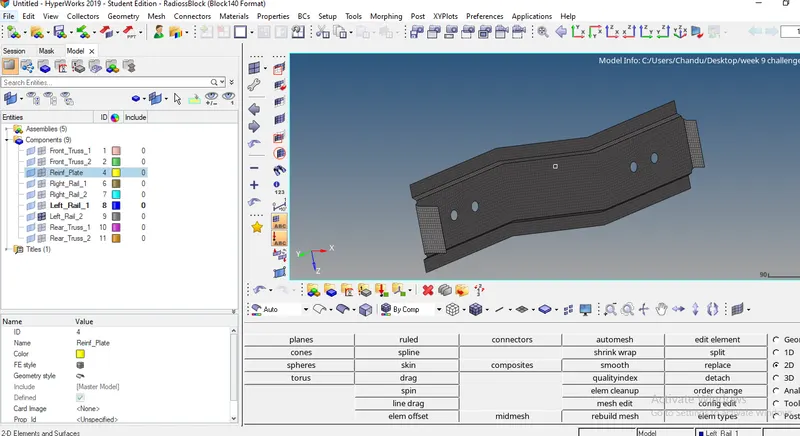
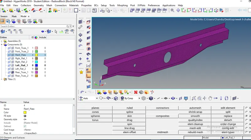
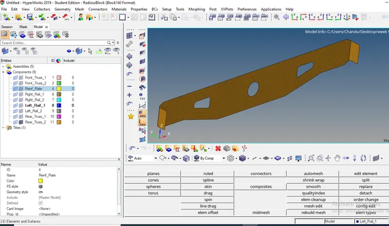
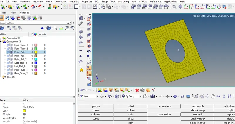
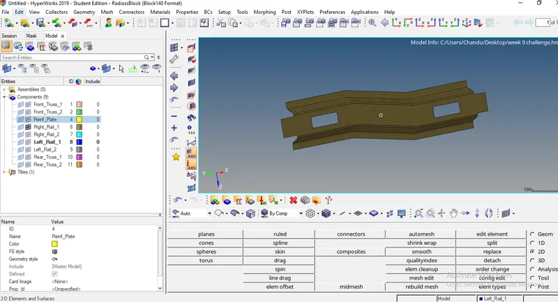
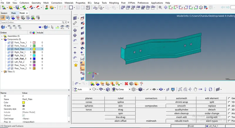
- after meshing created a new material then rename it as a steel , and created a new property then rename it as component and given thickness of 2mm , assigned these properties to each component.
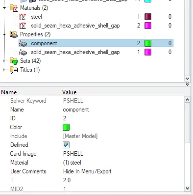
Creating connectors :-
- connectors are nothing but connect the two surfaces by using spot welds , seam welds or bolts .
- connectors are in 1D,2D,3D pannels all commands are same , we can use anyone .
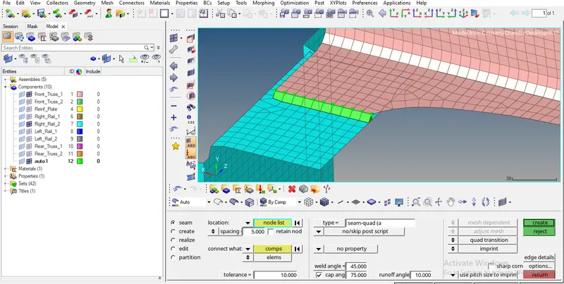
1. Right_Rail_2 & Front_truss_1:- Seam-Quad(angled+capped+L)
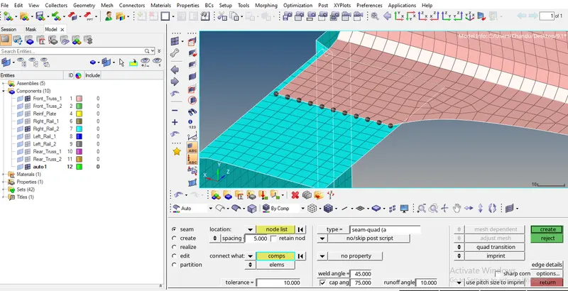
- go to 2D - CONNECTORS - SEAM - select nodes as shown in above pic - select two meshes - select Seam-Quad(angled+capped+L) type - give other parameters toerrence vaue, weld angle, cap angle ,runoff angle - click on create.
- we don't need to select nodes from two meshes , select nodes from one mesh and give tolerence value it automatically select nearest nodes within the tolerence zone in seected components.
- our element size is 5mm so we given SPACING value 5.00 , it means hypermesh select the nodes with 5mm gap.
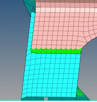
- connectors will destroy the mesh quaity , so after connecting remesh the elements with required quality criteria
2. Left_Rail_2 & Front_truss_1:- Quad elements
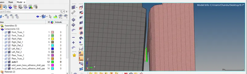
- go to 2D - CONNECTORS - SEAM - select nodes as shown in above pic - select two meshes - select Quad type connector - give tolerence vaue - click on create
3. Front_truss_2, Front_truss_1 & Right_Rail_1:- Spot weld with 3 Layers and 5 mm Diameter
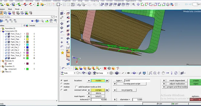
go to 2D - CONNECTORS -spot- select nodes for spot weld location - select weld type -select two components- select num layer (total 3)-give diameter 5mm- click on create
4. Front_truss_2, Front_truss_1 & Left_Rail_1:- Hexa (Adhesive)
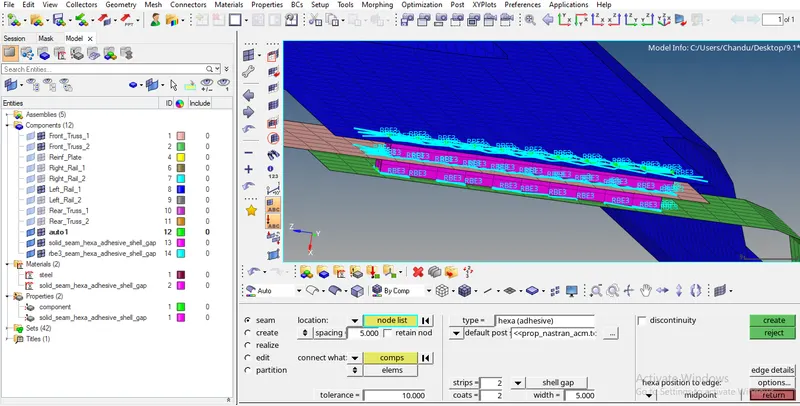
- go to 2D - CONNECTORS - seam - select hexa(adhesive) type - click on create
- here stripes means no.of vertical divisions , coats means no.of. horizontal divisons
5. Rear_truss_2 & Right_Rail_2:- Bolt Connector
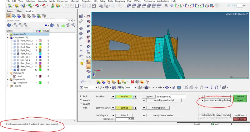
- go to 2D - CONNECTORS - bolt - select node location - select components- give toerence- select bot (general) type- click on create
- but it failed to connect , so we can realize this connector in two ways one is go to - view-browser - hypermesh - connector , then connector tab will open select faied connecter give a right click on it click on rerealize
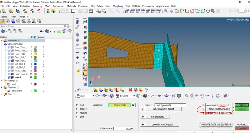
- other way to realize is , select realize option - click on connector- click on create
- in this case connector is failed because of there is no hole on any surfaces, to create bolt connector hole is necessary so change option from consider existing hole only to create hole if none.
6. Rear_truss_2 & Left_Rail_2:- Bolt Connector
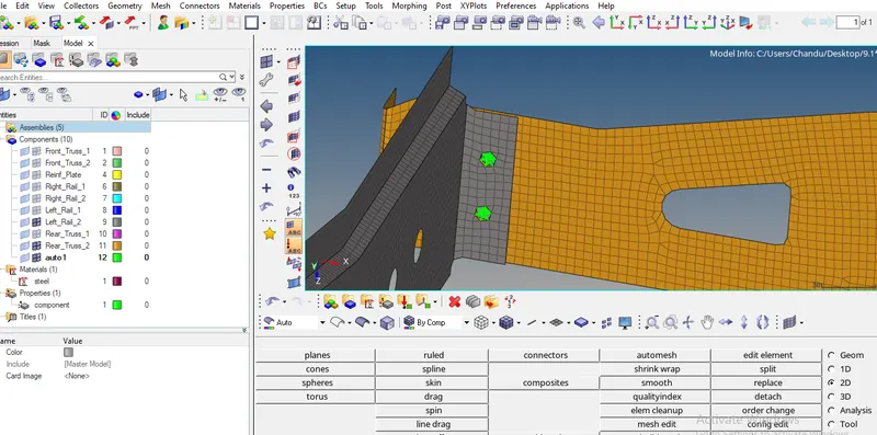
- followed the same procedure , mentioned in above case
7. Right_Rail_1 & Right_Rail_2:- Spot-weld with Rigid Elements
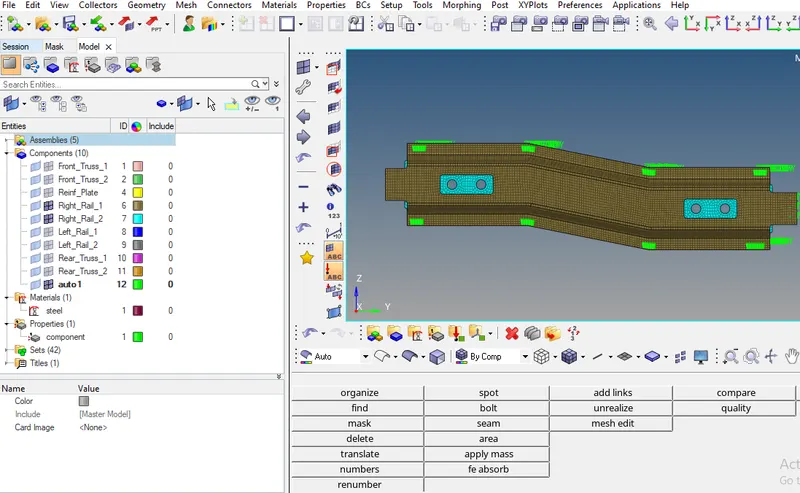
go to 2D - CONNECTORS -spot- select nodes for spot weld location - select two components- select rigid type- select num layer (total 2)-give diameter 5mm- click on create
8. Left_Rail_1 & Left_Rail_2:- Spot-weld with Spring Elements
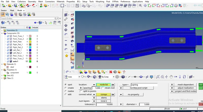
- followed same procedure , mentioned in above case , but changed type from rigid to spring.
9. Front Truss-1 & Reinforcement Pate :- seam - Quad elements
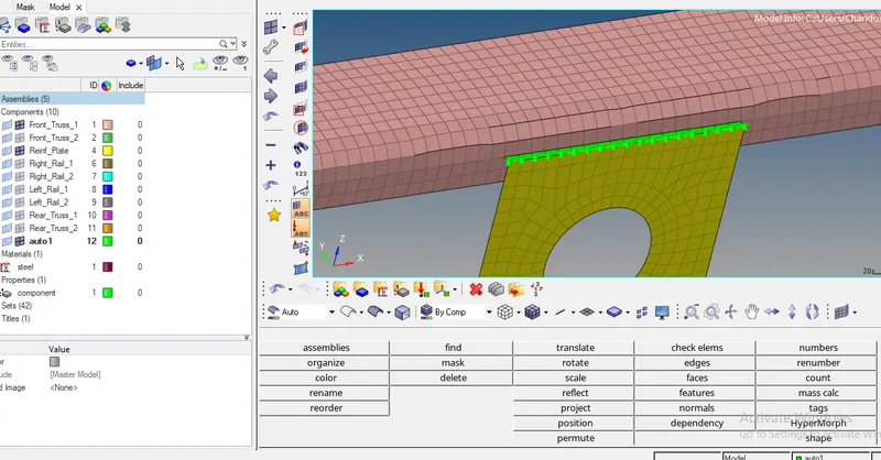
- go to 2D- connectors - seam - select nodes - select components- give tolerence - select type quad- click on create
10. Front Truss-2 & Reinforcement Pate :- seam - Quad elements
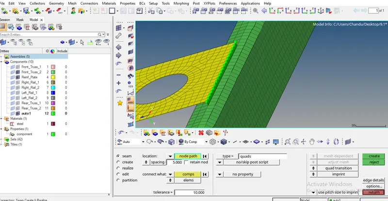
- followed same procedure , mentioned in above case
11. Rear Truss 2 & Rear Truss 1 :- seam - Quad elements
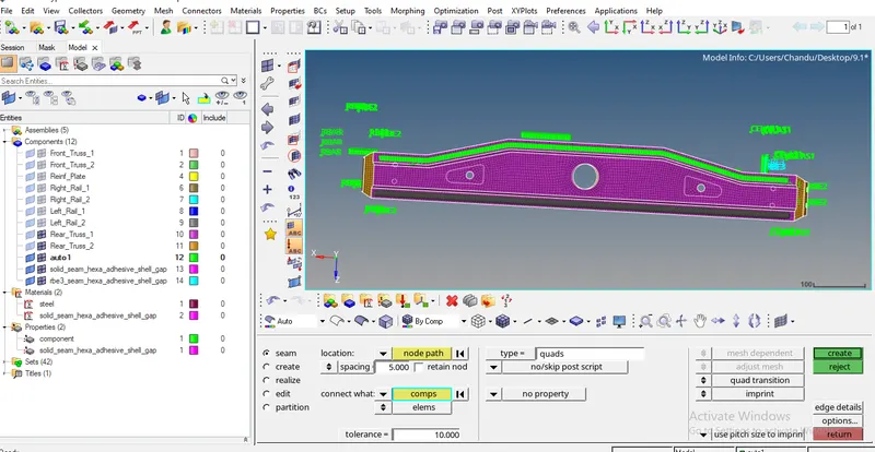
12. Left Rail1& Rear Truss2 :- Bolt connector
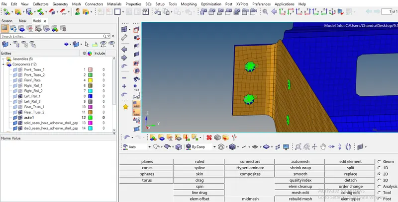
- go to 2D -connectors- bolt - select node location - select components- give toerence- select bot (general) type- change option from consider existing hole only to create hole if none - click on create
13. Right Rail 1& Rear Truss 2 :- spot - spring
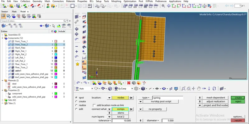
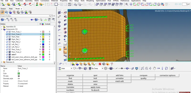
- go to 2D - CONNECTORS -spot- select nodes for spot weld location - select two components- select spring type- select num layer (total 2)-give diameter 5mm- click on create.
Result :-
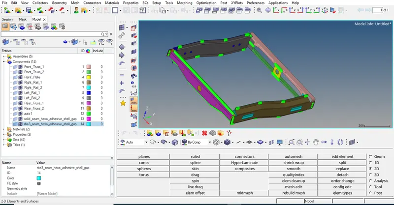
Some components were connected with with given connectors and remaing components were connected with appropriate connectors