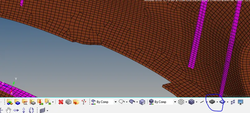
Week 12:Project-1-Meshing of Door Inner Panel Challenge
Aim :- mesh the Side Door component and assign thickness , Follow the Quality Criteria
Target Element Length = 4 Units
| S.N | Quality Criteria | Value |
| 1 | Aspect Ratio | 5 |
| 2 | Skewness | 45 |
| 3 | Warping | 15 |
| 4 | Taper | 0.5 |
| 5 | Min. Length | 2 Units |
| 6 | Max. Length | 6 Units |
| 7 | Min angle Quad | 45 |
| 8 | Max angle Quad | 135 |
| 9 | Min angle Tria | 20 |
| 10 | Max angle Tria | 120 |
| 10 | Tria % | 10 |
Procedure :-
- Import the given .hm file into hypermesh , go to - import model- select file- import.
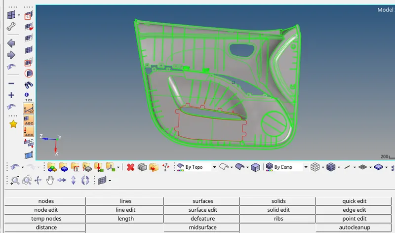
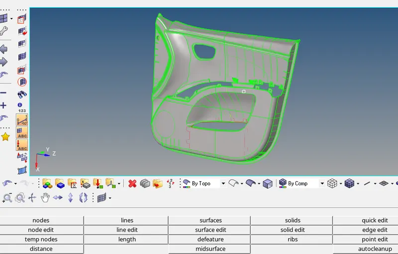
- It is difficult to generate midsurface for the given single complex component , so split this into 4 components.
- Put in BY COMPONENT view mode to see components with assigned colours.
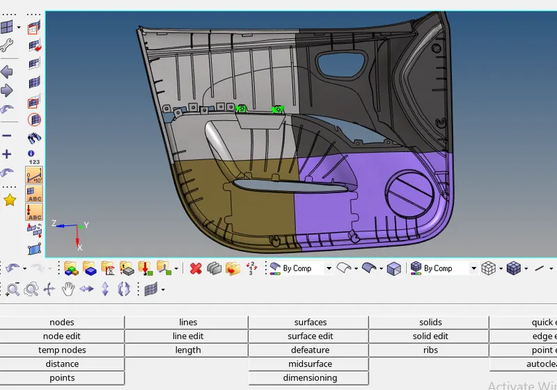
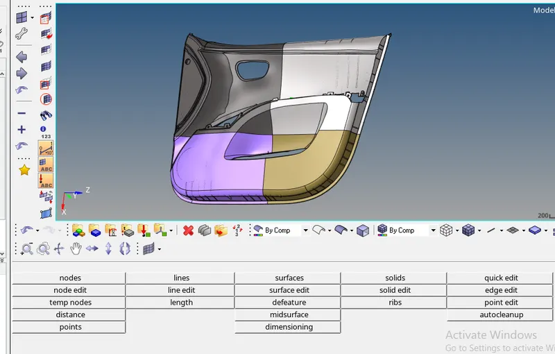
- For this type of components auto midsurface may not give proper midsurface ,so generate midsurface manually using OFFSET option.
- before offsettng the surface defeature the ribs , go to - geomtry- defature-surf fillets
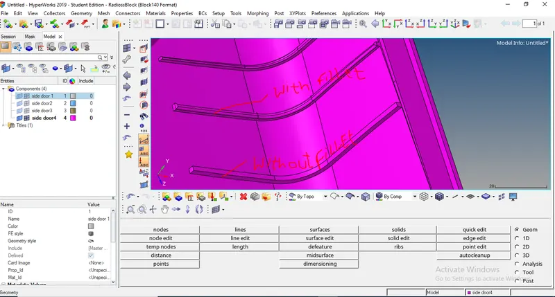
- go to - geometry -surface edit- offset , Taken styling surface (outer surface ) for reference
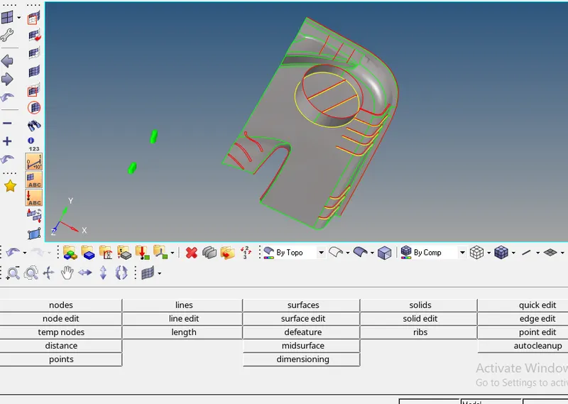
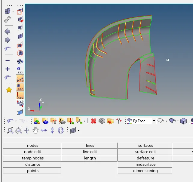
-
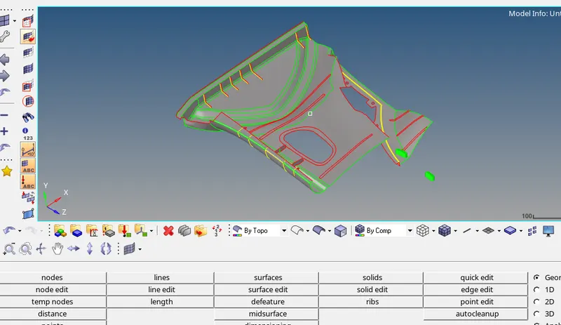
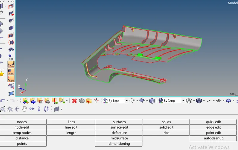
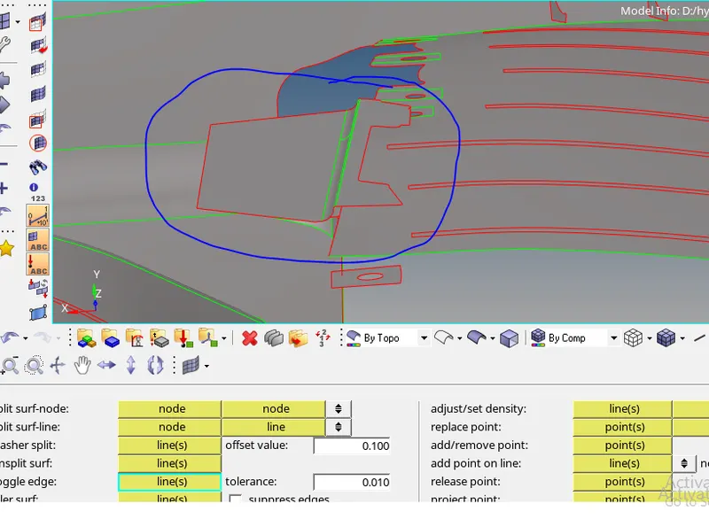
- Component like shown below , features are overlapping so project one feature onto another and represent both features on single surface
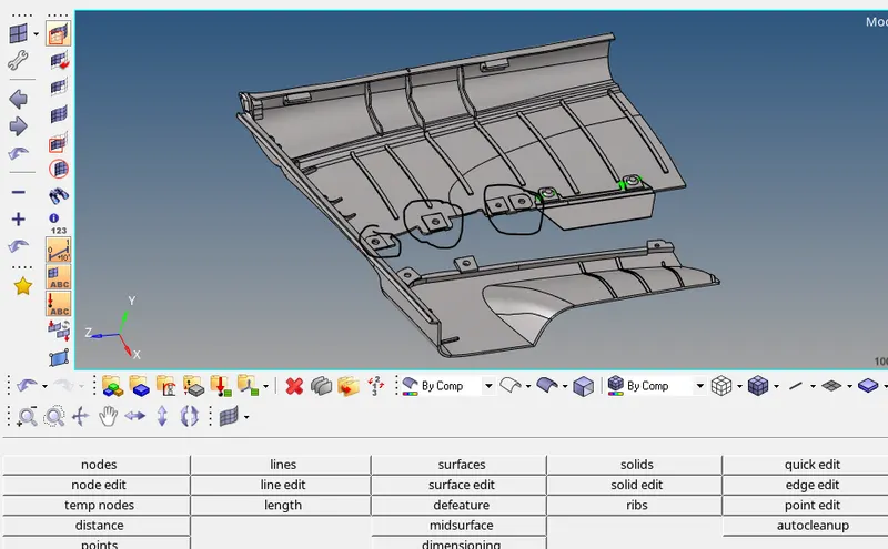
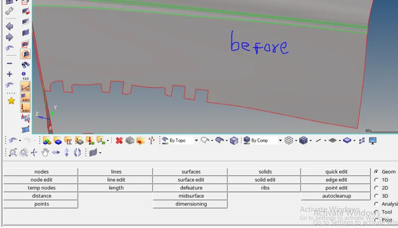
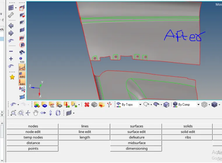
- After generating midsurface do geometry cleanup using defeature , surface edit ,quick edit options.
- on engineering surface(inner surface) ribs, snaps and some other features are there so after getting midsurface project these engineering features onto midsurface .
- go to - geometry -surface edit- extend , then edge turn into yellow color it means that edge is shares with three surfaces.
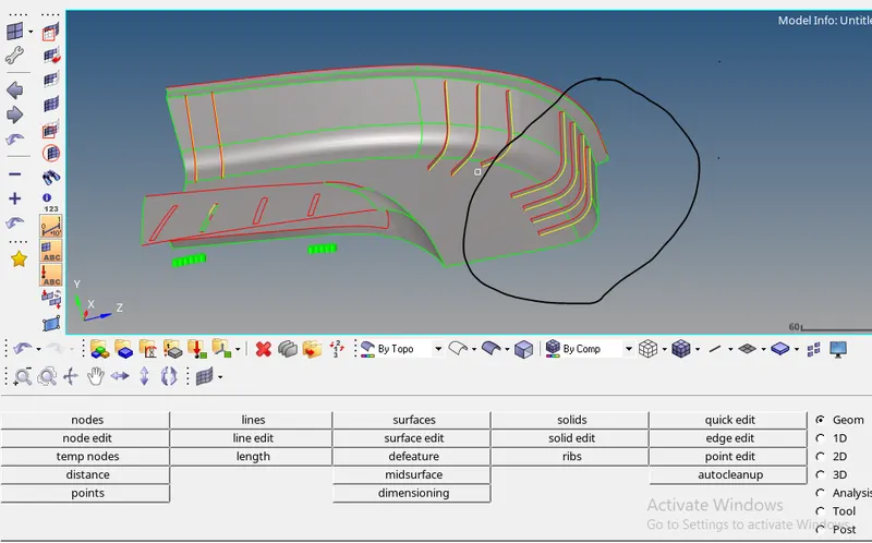
- After generating midsurface without any surface connectivity errors ,do meshing each component seperalately .
- go to - 2D - Automesh - element type (mixed)- element size (4)- click on mesh.
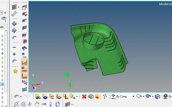
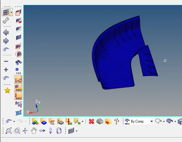
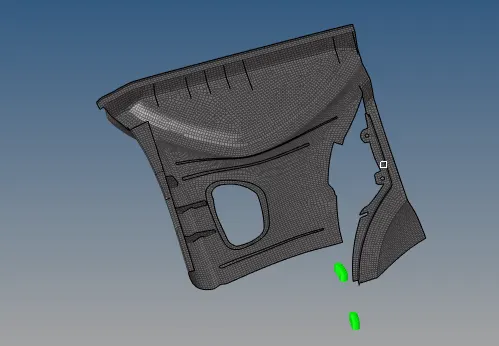
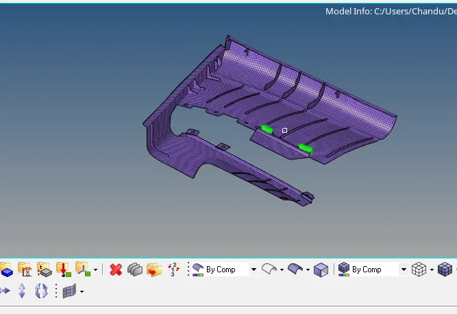
- After meshing go for quality check
- To give quality criteria , go to- preferences - criteria file settings
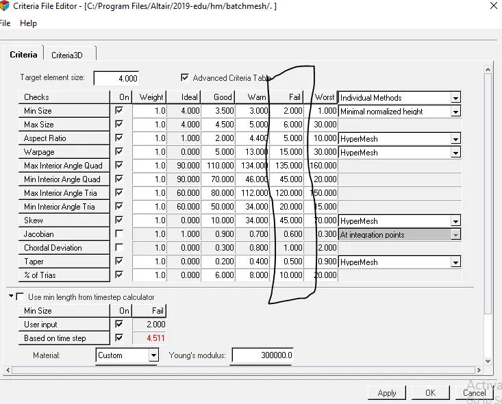
- After giving quality criteria go for quality check, 2D- quality index
- some elements will faile for quality try to clear thease fails using cleanup tools, node edit, edit element options.
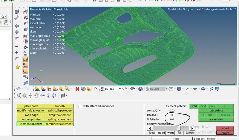
- In the above pic it shows no element will fail for quality
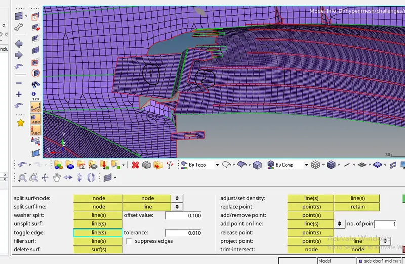
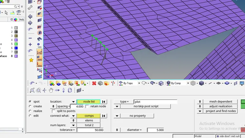
- In the above pic one surface is over another,so connect two surface using spot weld connectors
- go to-2D - connectors- spot
- After clearing quality check , assign thickness to the mesh
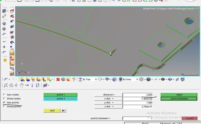
- press F4 , to measure thickness of components using two nodes option
- this side door component has different different thicknesses , so put one thickness elements in one component, another thickness elements in another compnent
- To create new component , right click-create -component.
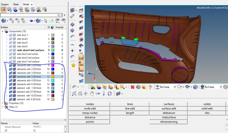
- while selecting elements use by face and by geometry options for selecting elements.
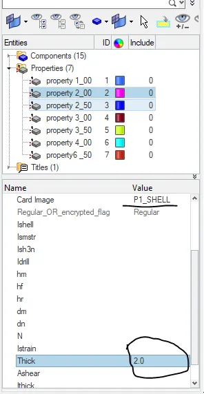
- Create new proprty with different thicknesses
- To create new property ,right click-create - property.
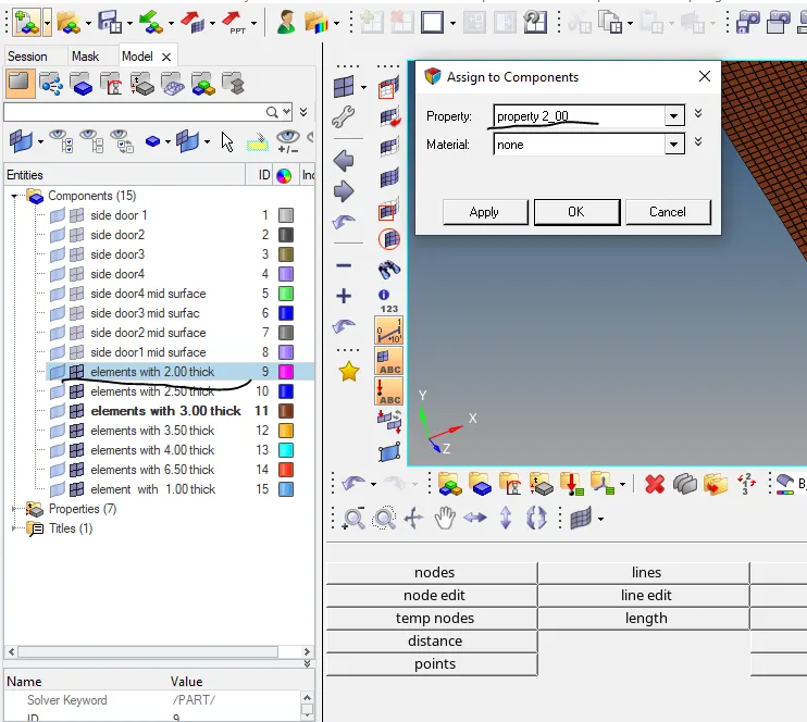
- after creating properties assign these properties to the respective components.
- To assign property, right click on component -assign-select property.
RESULT :-
BY THICKNESS MODE
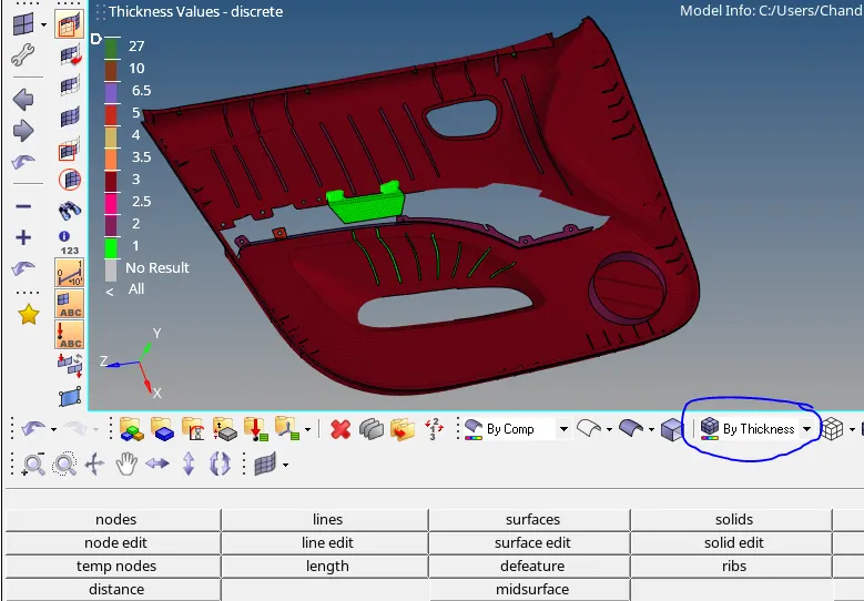
2D detailed element representation mode