Week 7-Long Piston With Cam
AIM:
To perform a transient analysis on a piston and cam mechanism model.
OBJECTIVE:
Perform a transient analysis on a piston and cam mechanism model with Frictionless contact, Frictional contact with frictional coefficient 0.1 and 0.2 for a total of 3 cases and find out the Equivalent Stress, Directional Deformation and Equivalent Elastic Strain and compare them for all the three cases.
PROCEDURE:
. Select Transient Structural, drag and drop into Project Schematic
. Let the default material be chosen under Engineering Data i.e structural steel.
. Under geometry tab, import the given geometry, double-click to open Space Claim to register the model and then update it.
. Based on the case, assign a frictionless/frictional connection between the barrel & cam as well as the cam & follower.
. The frictional co-efficient is 0.1 for case 2 and 0.2 for case 3 is provided as given condition.
. A fixed joint was assigned to the barrel.
. A revolute joint was given to the cam.
. A translational joint was given to the cam follower, within the barrel.
. The mesh size was set to 4mm, however the faces of the cam and follower that come in contact were given a face sizing of 1mm.
. Under transient structural tab, we set the analysis to 9 steps with timestep defined by time.
. A joint load is given to the revolute joint, with rotation in increments of 30deg(i.e from 30-270 degrees).
. Directional Deformation in X-axis, Equivalent Strain and Equivalent Stress plots are requested from the solver as outputs.
. Run the simulation by clicking on SOLVE.
The below conditions are used while doint the anslysis of piston and cam mechanism.
MATERIAL PROPERTIES
STRUCTURAL STEEL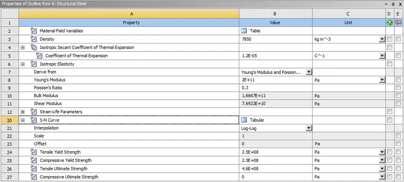
CONTACTS
CONTACT 1: Frictional cam follower to barrel Cam 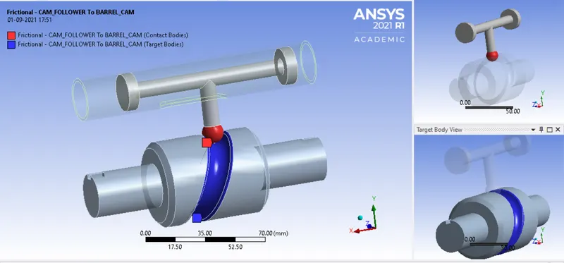
CONTACT 2: Frictional cam follower to Barrel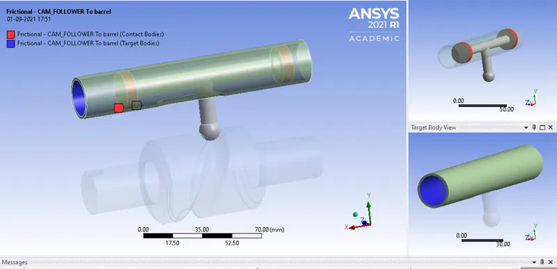
JOINTS
JOINT 1: FIXED( Ground to Barrel)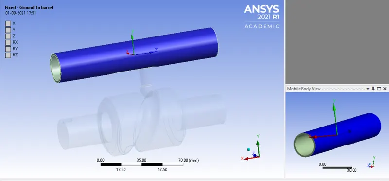
JOINT 2: REVOLUTE( Ground to Barrel Cam)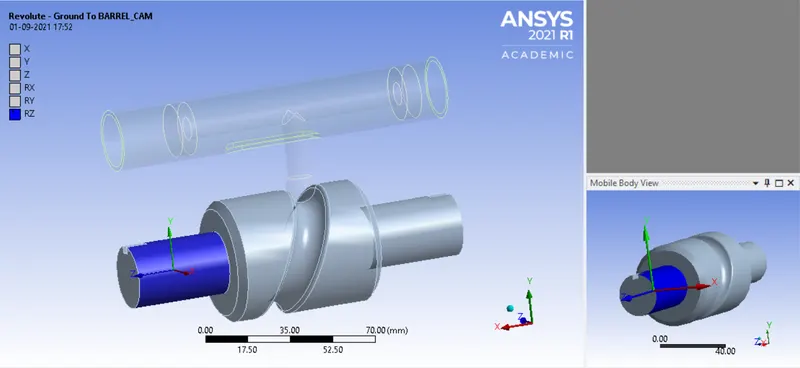
JOINT 3: TRANSLATION(Barrel to Cam follower)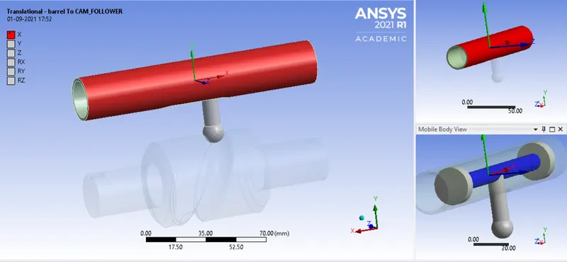
LOADS :
JOINT ROTATION(Long Piston)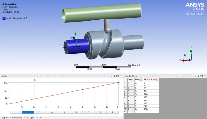
MESHING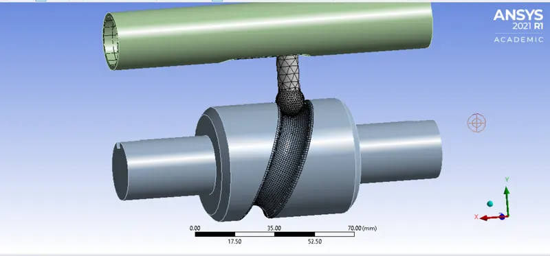
CASE 1 : Frictionless contact between Barrel & Follower and Follower & Cam
EQUIVALENT STRESS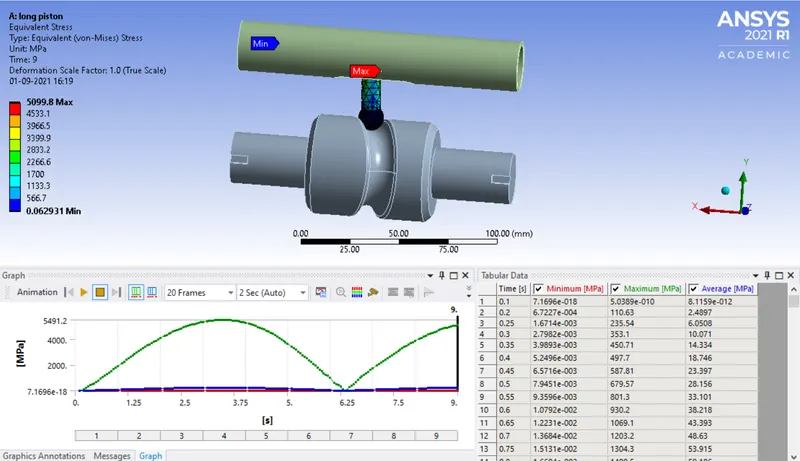
EQUIVALENT ELASTIC STRAIN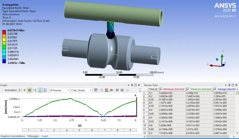
DIRECTIONAL DEFORMATION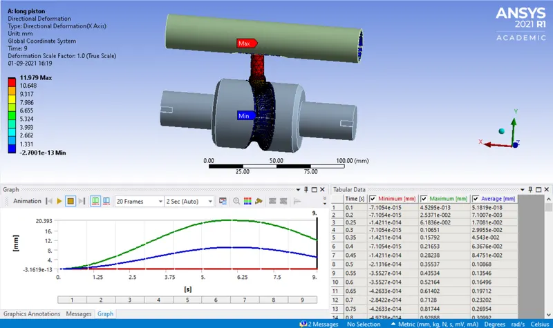
CONTACT PRESSURE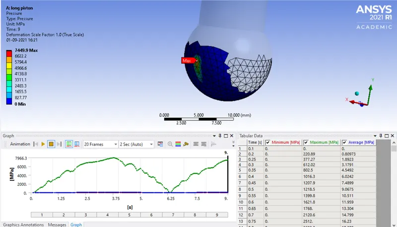
CASE 2: Frictional contact between Barrel & Follower and Follower & Cam with frictional coefficient = 0.1
EQUIVALENT STRESS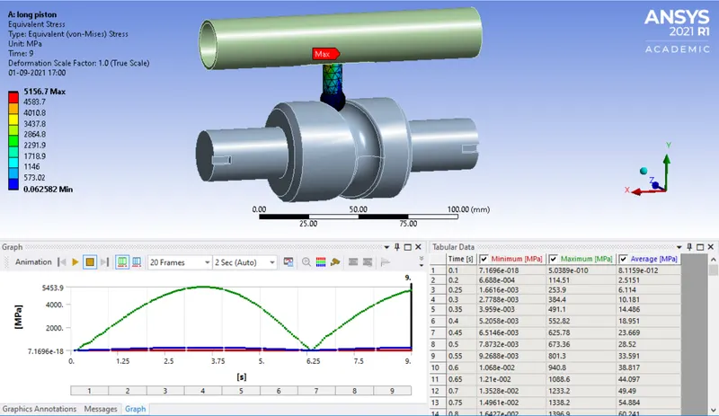
EQUIVAELNT ELASTIC STRAIN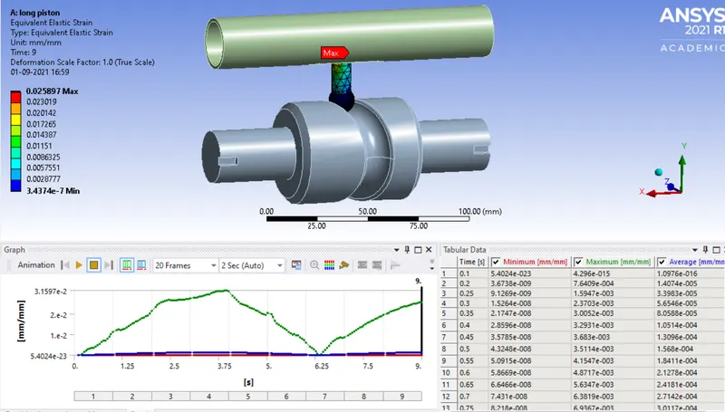
DIRECTIONAL DEFORMATION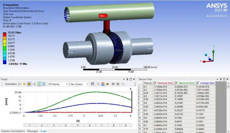
CONTACT PRESSURE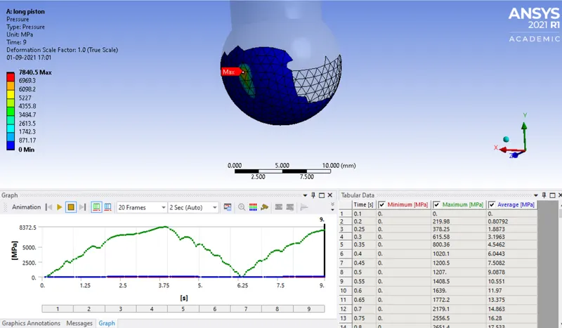
CASE 3: Frictional contact between Barrel & Follower and Follower & Cam with frictional coefficient = 0.2
EQUIVALENT STRESS 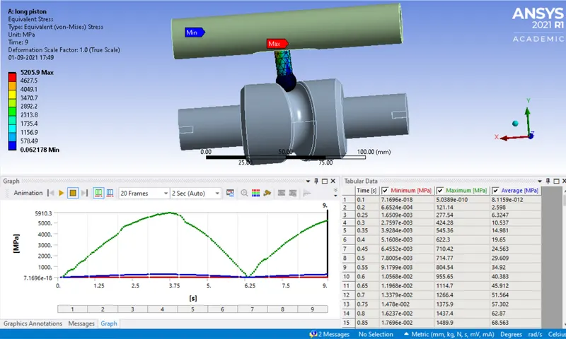
EQUIVALENT ELASTIC STRAIN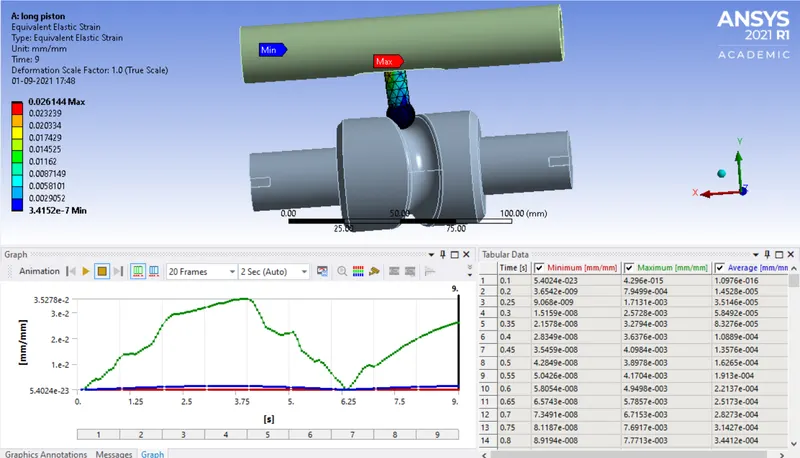
DIRECTIONAL DEFORMATION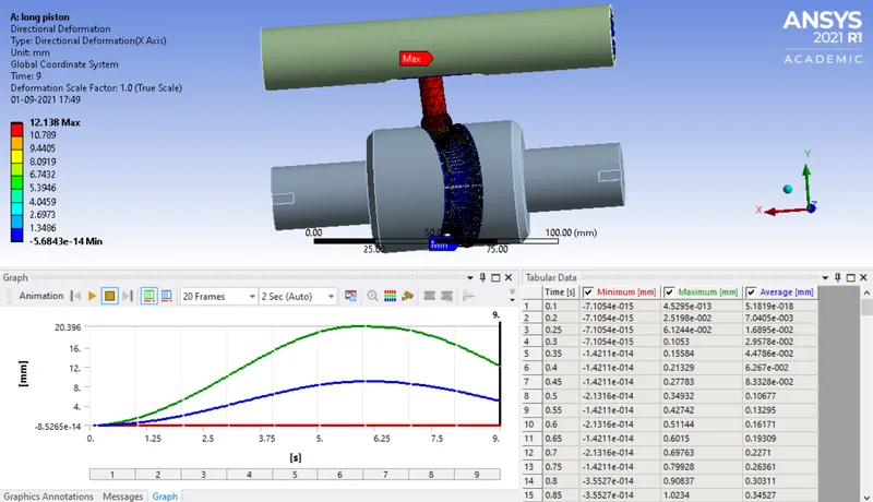
CONTACT PRESSURE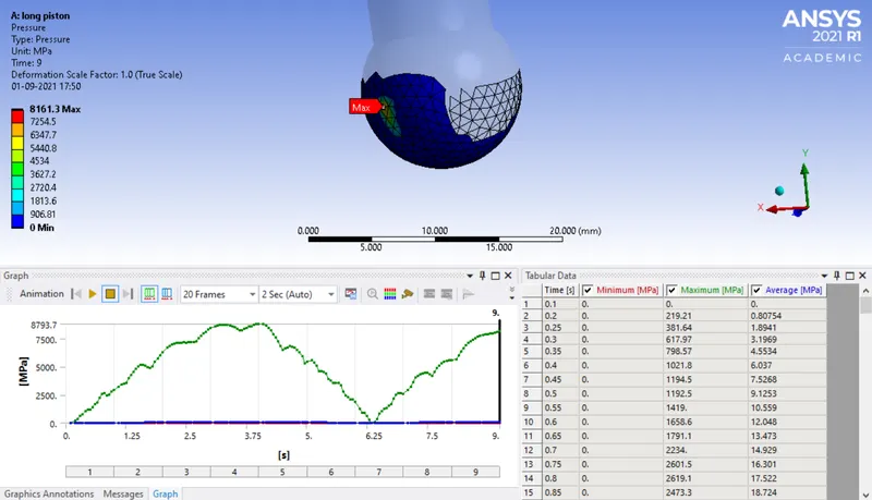
RESULTS AND CONCLUSION
|
Case |
Frictional Co-efficient |
Eq. Stress (MPa) |
Eq. Strain |
Directional Def. (mm) |
|
1 |
0 |
5099.8 |
0.025612 |
11.979 |
|
2 |
0.1 |
5156.7 |
0.025897 |
12.057 |
|
3 |
0.2 |
5205.9 |
0.026144 |
12.138 |
From the above table it is clear that as the friction coefficient increases between Barrel & Follower and Follower & Cam the Eq. stress, eq. strain and the directional deformation increases. This is due to the resistance in motion because of friction. The system tries to overcome that resistance and because of that reason the stress, strain and deformation increases in case of friction provided with frictional coefficient of 0.2.