Week 2 Bevel Gear Challenge
AIM:
To understand the concept of the grisd dependency test and then run the simulation on bevel gear with 4mm,5mm and 6mm element size to evaluate the equivalent stress,equivalent elastic strain and total deformation on bevel gear.
OBJECTIVE:
Getting the overall concept of the grid dependency test and how it uses in the Ansys workbench for the simulation process, the same process needs to be applied on the bevel gear component with different element size such as 4mm, 5mm, and 6mmm but the facing of the gear should be consistent at 1.75mm.
.
GRID DEPENDENCY TEST:
A simple concept to understand the grid dependency test of mesh refinement test in the finite element analysis that analysis begins with a coarse mesh and it is refined to a finer mesh for each run until the result does not change significantly. The finer mesh flow will have high accuracy results compare to the default mesh generated.
The main flaw of the finer mesh flow has the elements and node size will increase compared to the coarse mesh size and it will take a lot of time to evaluate the result. As this test will benefit for an accurate result because of the high density mesh.
The main concept of this test will be to find optimum mesh size for the evaluation, where it is neither too coarse mesh nor finer mesh, as it will consume a lot of computing time to generate results.Because of it, the grid dependency test will be evaluated on the bevel gear to obtain the optimum mesh size.
Bevel Gear- This type of gear where axes of two shaft intersect and the tooth-bearing faces of the gear themselves are conically shaped. The bevel gear is mostly mounted where the shafts that are 90 degrees to each other but they can be worked at other angles as well.
PROCEDURE:
. Select Static Structural, drag and drop into Project Schematic
. Choose material as structural steel which is ame for all the 3 cases, under Engineering Data
. Under geometry tab, import the given Bevel Gear geometry and open it in spaceclaim,draw a circle of 45mm on bigger gear then then remove that 45mm area by holding it and pulling it out of the gear then do the same case for smaller gear , draw a circle of 25mm and then drag that area out of the gear by pulling it out.
. Then in Mechanical Module, assign a frictional connection between the gear teeth. (Right to Left)
. Assign revolute joints to both the gear. (Ground to Big/Small)
. A mesh element sizes are varied for case to case as given in the problem but face sizing is same for all the cases i.e 1.75mm.
. Face sizing is done on the faces that are critical in the analysis (means gear teeths).
. Under static structural tab, we enter the values of rotational motion for one gear (smaller) and moment for other gear (bigger one).
. The small gear is made to rotate up to 120deg in six steps of 20deg each.
. The Big gear is made to rotate with a moment of 100Nmm in counterclockwise motion.
. Total Deformation, Equivalent Elastic Strain and Equivalent Stress plots are requested from the solver as outputs
. The same process is repeated for each case by changing the mesh size i.e 4mm,5mm and 6mm.
The conditons below are similar for all the three cases.
MATERIAL PROPERTIES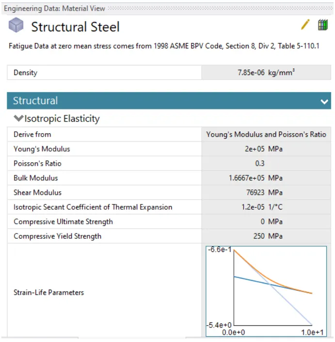
.CONTACTS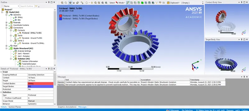
.JOINT(BIG)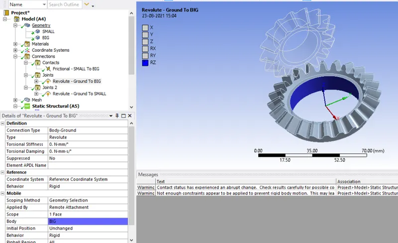
.JOINT(SMALL)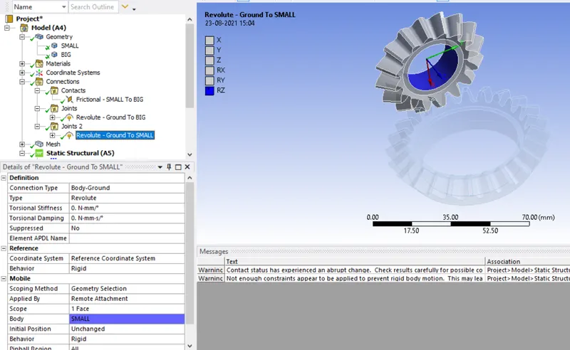
.JOINT MOMENT(BIG)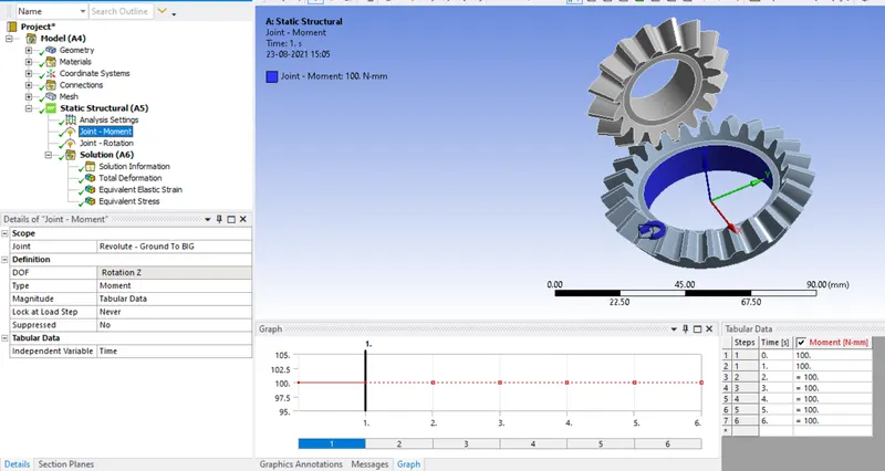
.JOINT ROTATION(SMALL)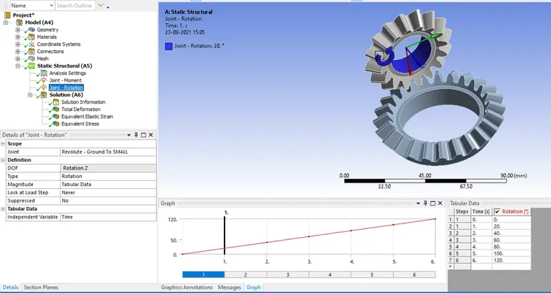
.ANALYSIS SETTINGS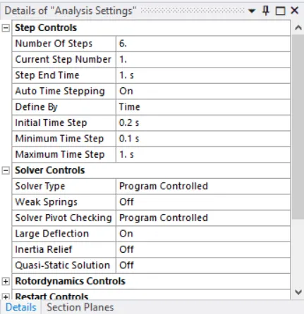
CASE 1: Here mesh of 6mm is applied on the whosle body and then face sizing of 1.75mm is done on all the faces of the teeth .
.6MM MESH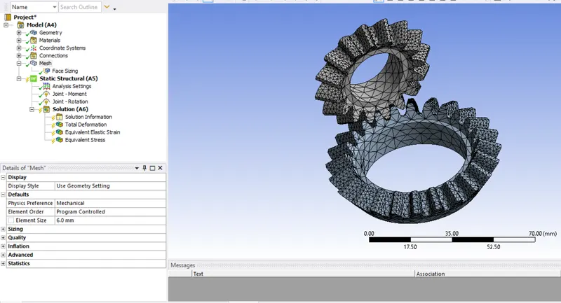
.EQUIVALENT STRESS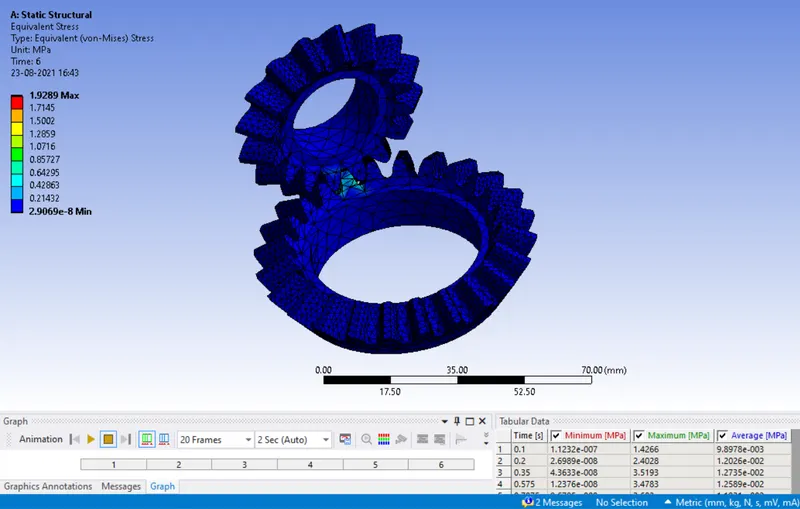
.EQUIVALENT ELASTIC STRAIN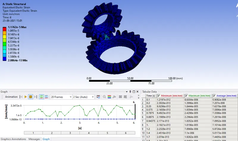
.TOTAL DEFORMATION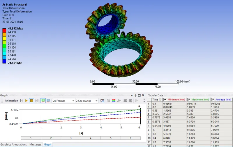
.RESULT SUMMARY
CASE 2: Here the meshing of 5mm is done on the gears but on the teeth of the gears the meshing of 1.75mm is done to get better results .
.5MM MESH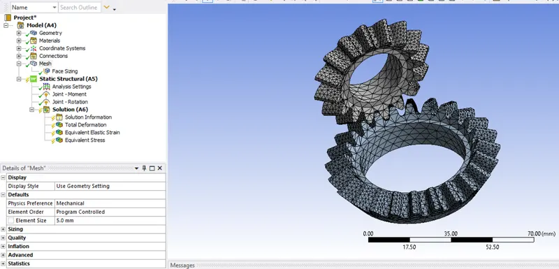
.EQUIVALENT STRESS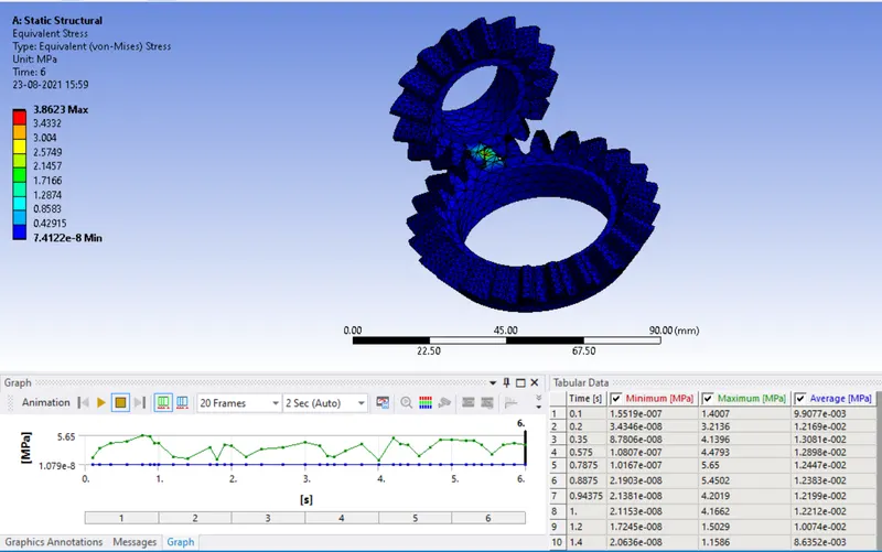
.EQUIVALENT ELASTIC STRAIN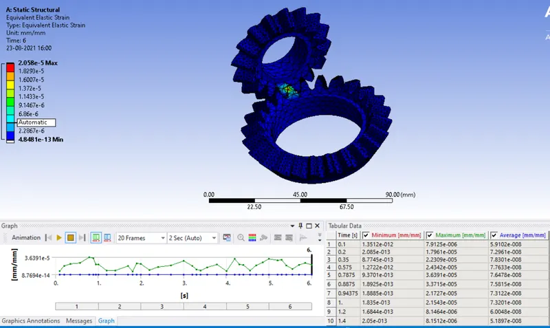
.TOTAL DEFORMATION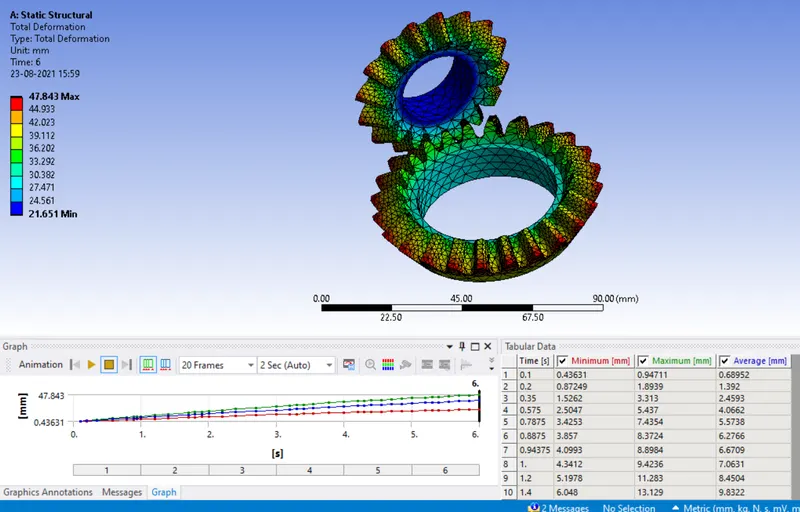
.RESULT SUMMARY
.CASE 3: Here the meshing of 4mm is done to the both of the gears and face sizing of 1.75mm is done on the gear teeths.
. 4MM MESH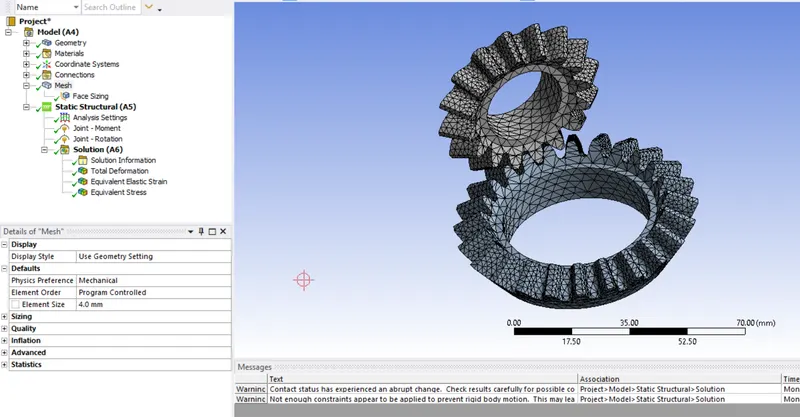
.EQUIVALENT STRESS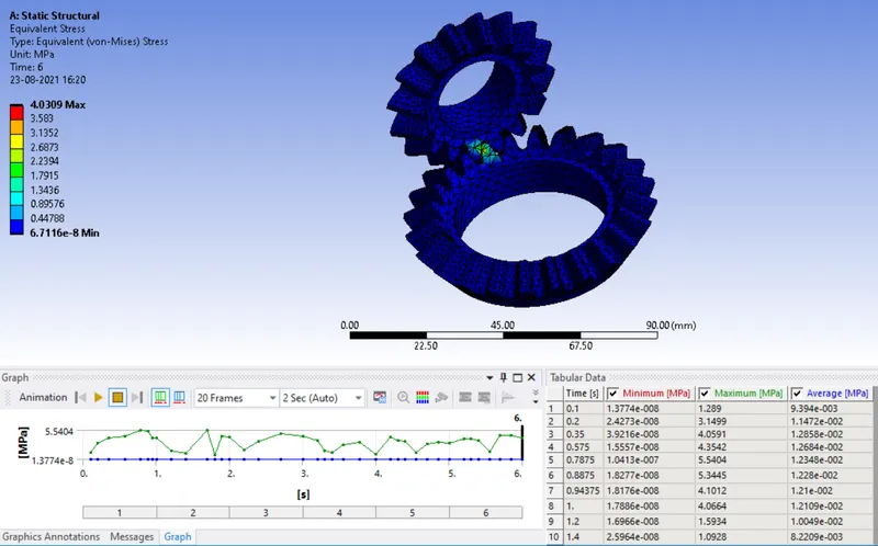
.EQUIVALENT ELASTIC STRAIN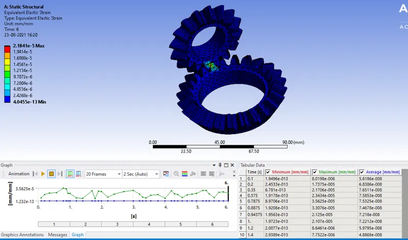
.TOTAL DEFORMATION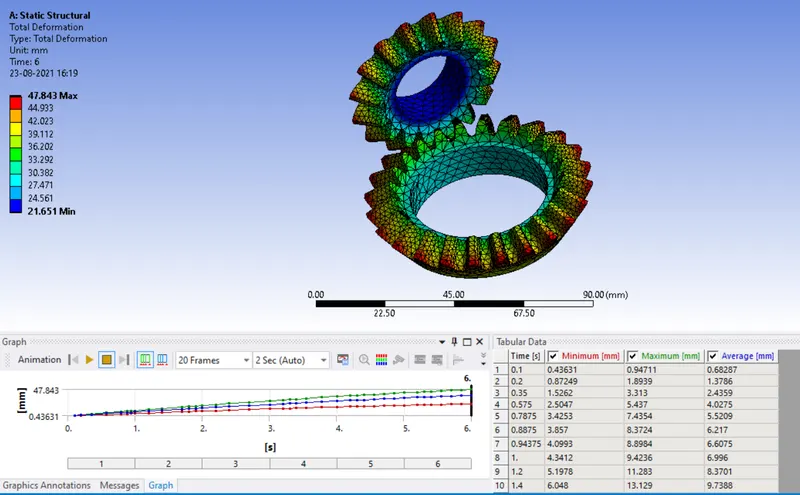
.RESULT SUMMARY
RESULTS COMPARISON
|
Mesh Size(mm) |
Equivalent Stress (N/mm2) |
Equivalent Elastic Strain(max) |
Total Deformation (mm) |
|
|
6 |
1.9289 |
1.1762E-005 |
47.872 |
|
|
5 |
3.8623 |
2.058E-005 |
47.843 |
|
|
4 |
4.0309 |
2.1841E-005 |
47.843 |
CONCLUSION:
As we can see that along the equivalent non-vises stress evaluates the result that the increase in the number of numbers means fine mesh gives more accurate result compared to large element size as we look the table and result of simulation 6mm size equivalent stress is 1.9289 (max), 5mm size is 3.8623 (max) and for 4mm size is 4.0309(max).
The result for equivalent strain evaluates that for 6mm size minimum strain is 1.1762e-005 (max) for 5mm size 2.058e-005 (max) and for 4mm size is 2.1841e-005 (max), the finer mesh gives much accurate result to obtain the starin value.
But comparing those results to the total grid dependency test doesn't seem to many changes as it is equal to all three mesh sizes with similar results but it is seen from the results that more finer the mesh more accurate the results and with the values of mesh very low (means finer ) then there is less difference between the results as compared to the body with coarse mesh or highher mesh sizings.