Week 2 Railwheel and Track
AIM:
Perform a static structural analysis on the Railwheel and Track setup and determine lifecycle, stress, strain, and total deformation provided by the wheel running on the track by the given forces.
OBJECTIVE:
The main focus of this analysis is to evaluate the result of the product life cycle ,stress, strain, and total deformation in the static structural material (i.e structural steel ). This anslysis of railwheel and track is completed by two cases
Case 1: Load of 100000 N.(100KN)
Case 2: Load of 5 times of 100000N.(500KN)
And Implement user-defined results and compare both results in all aspects of the evaluation
PROCEDURE:
. Select Static Structural, drag and drop into Project Schematic
. Choose material as structural steel, under Engineering Data
. Under geometry tab, import the given Rail wheel track geometry, double-click to open Space Claim and update the model
. Then in Mechanical Module, assign a frictional connection between the wheel and track with 0.3 coefficient of friction.
. Also assign a frictionless contact between bearing and wheel in contact 2.
. In joint 1 : The track is made fixed with a fixed joint.
. In joint 2: Bearing is given a translational joint ensuring that it will move on the railway track
. In joint 3: The wheel is given a planar joint so that it will move in one plane only.
. A mesh element size is given 50mm for overall body.
. Face Sizing is done on wheel face and track face 35mm element size. This is done to generate a better mesh on the faces that are critical in the analysis and to calculate better results .
. Under static structural tab, we add Joint- Displacement and enter the values of translational motion the wheel in 5 steps of 100mm each.
. Bearing load value is entered in the downward direction(negative y in 2 Cases i.e firstly 100KN and 500KN))
. Total Deformation, Equivalent Elastic Strain and Equivalent Stress plots ,fatigue life and user defined results expression to calculate Total deformation) are requested from the solver as outputs.
These below conditions will be same for both the cases.
MATERIAL PROPERTIES : Structural Steel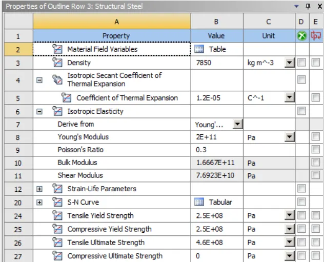
CONTACTS :
CONTACT 1: Between wheel and Rail track(Frictional)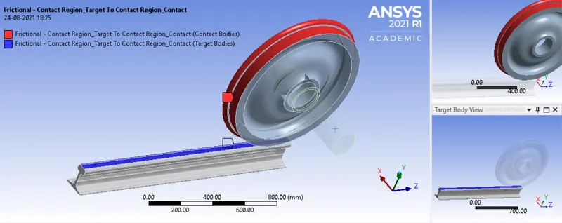
CONTACT 2: Between Driving shaft and Wheel(Frictionless)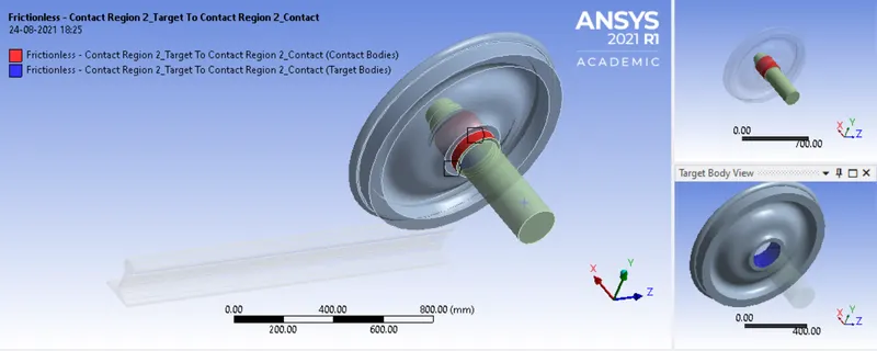
JOINTS:
JOINT 1: Fixed 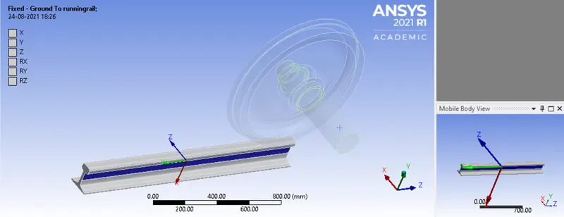
JOINT 2: Planar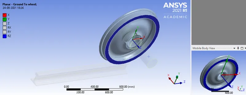
JOINT 3: Translational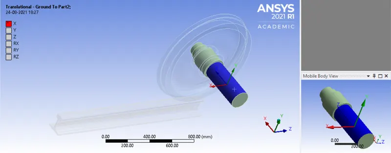
JOINT DISPLACEMENT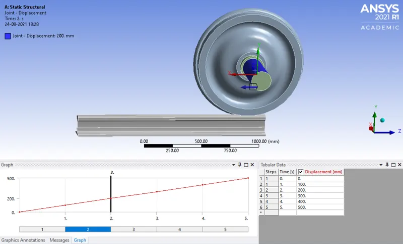
ANALYSIS SETTINGS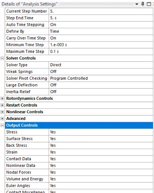
MESHING: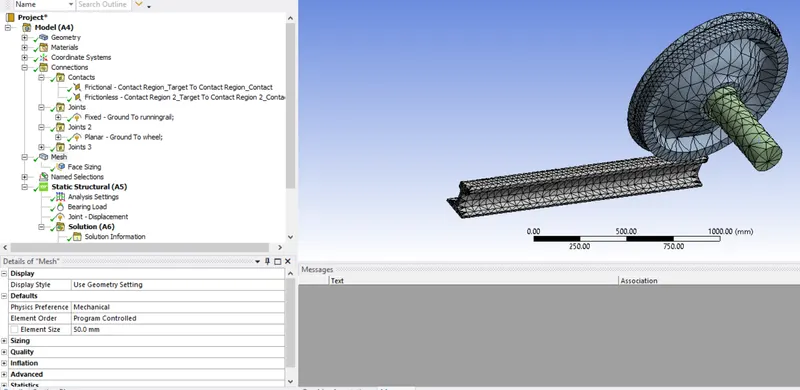
CASE 1 : In this case ,firstly the bearing load of 100KN and 500KN is applied to the part of the wheel(in contact with shaft) and then the result of both the cases are compared.
TOTAL DEFORMATION(100KN LOAD)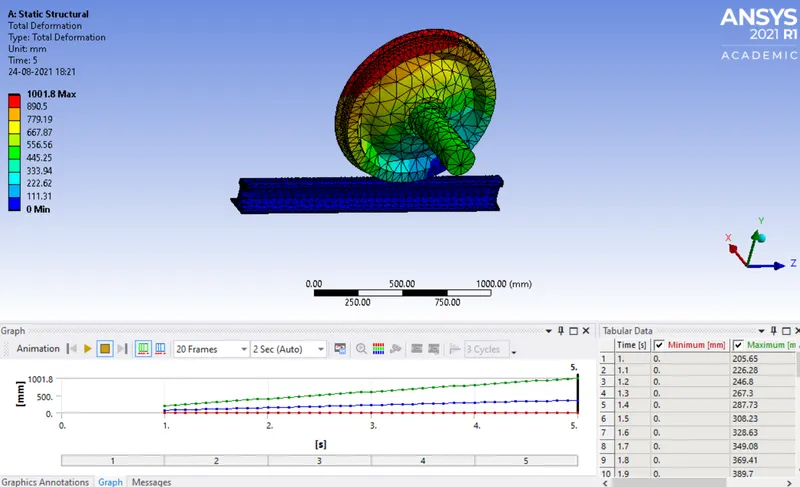
TOTAL DEFORMATION (500KN LOAD)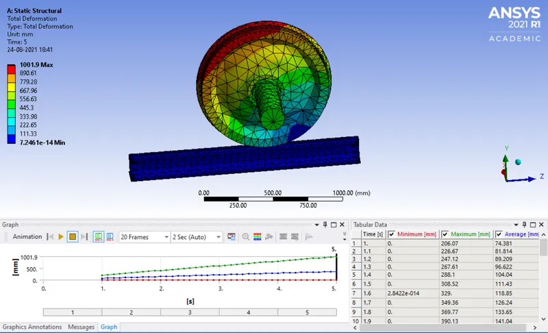
EQUIVALENT STRESS(100KN LOAD)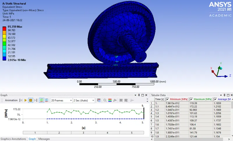
EQUIVALENT STRESS(500KN LOAD)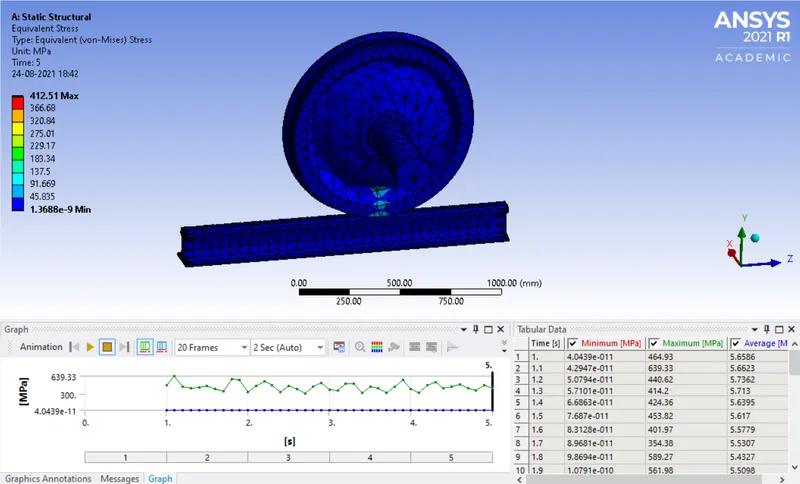
EQUIVALENT ELASTIC STRAIN(100KN LOAD)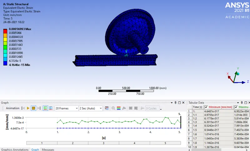
EQUIVALENT ELASTIC STRAIN(500KN LOAD)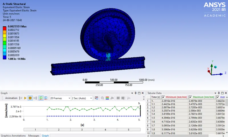
FATIGUE LIFE(1OOKN LOAD)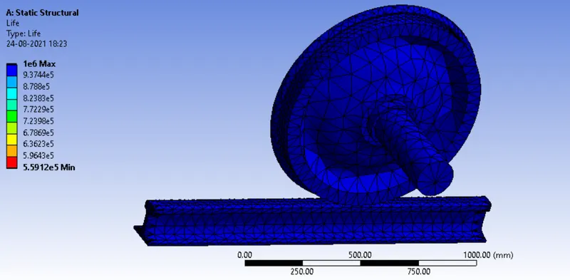
FATIGUE LIFE(500KN)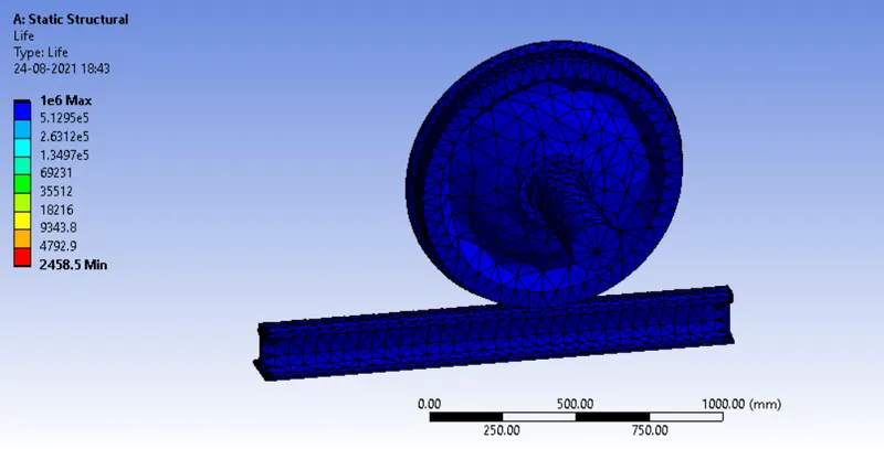
RESULTS COMPARISON:
| Bearing load (N) | Equivalent stress(MPA) | Total deformation(mm) | Fatigue life |
| 100KN | 95.359 | 1001.8 | 1e6 |
| 500KN | 412.51 | 1001.9 | 1e6 |
It can be seen from the result that the stress is increased by 4 times but the faligue life and total deformation and fatigue life remains the same.
CASE 2: Compare the used defined result for total deformation of both the cases (100KN and 500KN).
The expression for user defined result to calculate total deformation is sqrt(Ux^2+Uy^2+Uz^2)
USER DEFINED RESULT (100KN) 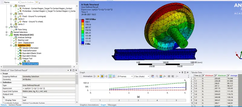
USER DEFINED RESULT (500KN LOAD)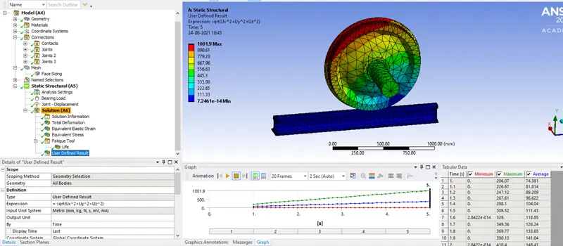
CONCLUSION:
As we can see from the above images that the USD value to calculate total deformation in the first case where 100KN load applied is 1001.8mm max and for the 500KN load is 1001.9mm max which are just same .