Long Piston With Cam
AIM:
- To perform transient structural analysis of Long piston and cam model and evaluate the results for Frictionless, Frictional 0.1 and Frictional 0.2 contacts.
OBJECTIVES OF THE PROJECT:
- To assign Structural steel material for the parts.
- To define the contacts for the cam, follower and barrel.
- To define barrel and Cam as rigid bodies.
- To define Joint loads.
- To mesh the model.
- To define face sizing for the contact faces.
- To evaluate the stress, deformation and directional velocity in the work piece.
PROCEDURE:
- Case 1 – Frictionless
- OPEN WORKBENCH21 > NEW PROJECT > TRANSIENT STRUCTURAL.
- This will start a new transient structural project.
- Rename the project as Frictionless.
- Go to ENGINEERING DATA > STRUCTURAL STEEL.
- Then double click on Geometry. This will open the Spaceclaim.
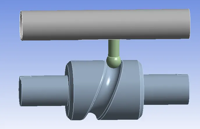
- In Space claim check the model for any dents or irregularities.
- The geometry looks good, exit the Spaceclaim.
- Then double click on Model. This will open Mechanical module.
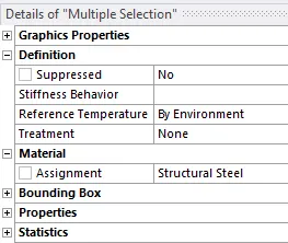
- Now, rename the geometry as Barrel, Barrel cam and Follower.
- Then assign Structural steel material to all the parts.
- Then go to CONTACTS > CONTACT > TYPE = FRICTIONALESS.
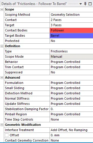
- Create contacts for Follower to Barrel and Follower to Barrel cam.
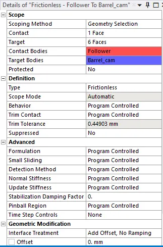
- This will define the contacts for both the parts.
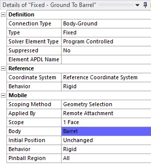
- CONNECTIONS > INSERT > JOINT LOAD > BODY-GROUND > TYPE = FIXED > SCOPE = BARREL FACE.
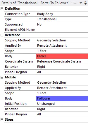
- CONNECTIONS > INSERT > JOINT LOAD > BODY-BODY > TYPE = TRANSLATIONAL > SCOPE = BARREL FACE > SCOPE = FOLLOWER.
- CONNECTIONS > INSERT > JOINT LOAD > BODY-GROUND > TYPE = REVOLUTE > SCOPE = BARREL CAM FACE.
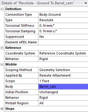
- This will define the Joint loads.
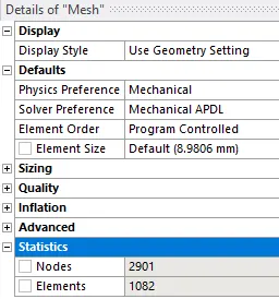
- Now, go to MESH > INSERT > SIZING > ELEMENT LENGTH = 3MM > SCOPE = CONTACT FACES > MESH > SIZING > ADAPTIVE SIZING = NO > GENERATE MESH.
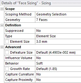
- The mesh will be generated on the model.
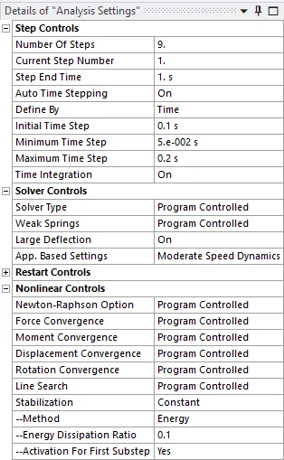
- Then go to STATIC STRUCTURAL > ANALYIS SETTINGS > NO OF STEPS = 9 > FOR STEP 1 > INITIAL TIME STEP = 0.1 > MAXIMUM TIME STEP = 5E-2 > MINIMUM TIME STEP = 0.2 > LARGE DEFLECTION = ON > WEAK SPRINGS = PROGRAM CONTROLLED > STABILIZATION = CONSTANT > ENERGY DISSIPATION RATIO = 0.1 > ACTIVATION FOR FIRST SUBSTEP = YES.
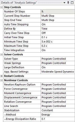
- Then go to STATIC STRUCTURAL > ANALYIS SETTINGS > NO OF STEPS = 9 > FOR STEPS 2-9 > INITIAL TIME STEP = 0.1 > MAXIMUM TIME STEP = 5E-2 > MINIMUM TIME STEP = 0.3 > LARGE DEFLECTION = ON > WEAK SPRINGS = PROGRAM CONTROLLED > STABILIZATION = CONSTANT > ENERGY DISSIPATION RATIO = 0.1 > ACTIVATION FOR FIRST SUBSTEP = YES.
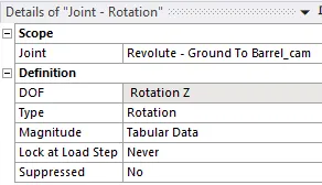
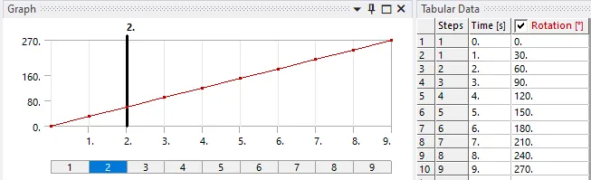
- Go to STATIC STRUCTURAL > INSERT > JOINT = REVOLUTE – GROUND TO BARREL > TYPE = ROTATION > MAGNITUDE = TABULAR DATA.
- Then, go to SOLUTION > INSERT > STRESS > STRAIN > DIRECTIONAL VELOCITY.
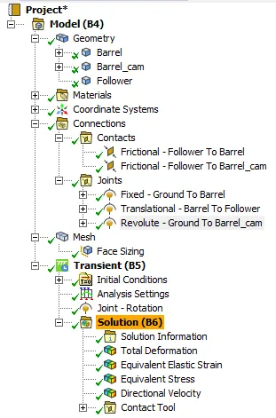
- This will set the output results.
- Then SOLUTION > SOLVE.
- Case 2 – Frictional – 0.1
- Create a duplicate project of the case 1.
- Then open Mechanical module.
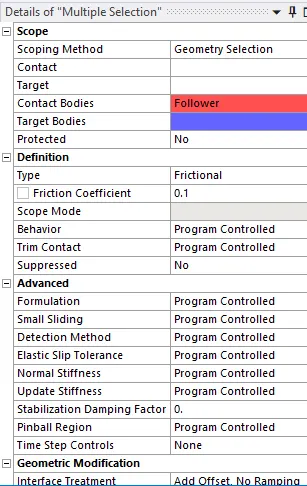
- In this case, change the CONTACT TYPE = FRICTIONAL > FRICTION FACTOR = 0.1.
- Go to SOLUTION and SOLVE.
- Case 3 – Frictional - 0.2
- Create a duplicate project of the case 1.
- Then open Mechanical module.
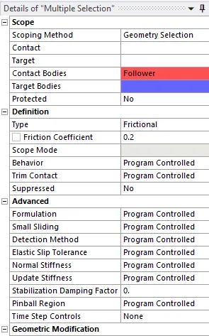
- In this case, change the CONTACT TYPE = FRICTIONAL > FRICTION FACTOR = 0.2.
- Go to SOLUTION and SOLVE.
RESULTS:
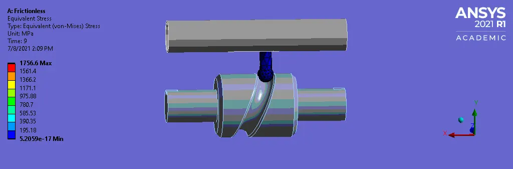
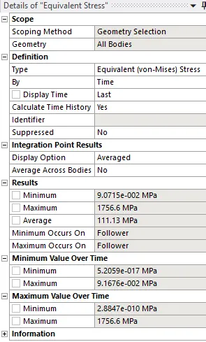
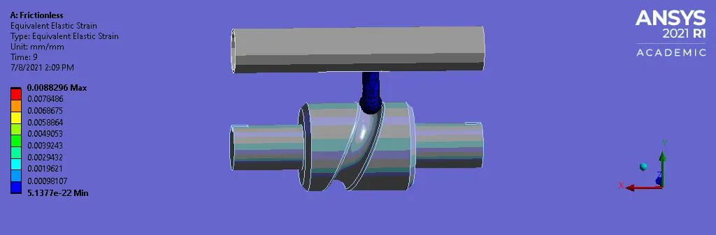
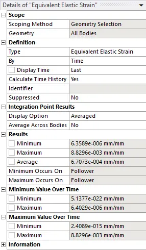
- Case 1 – Frictionless
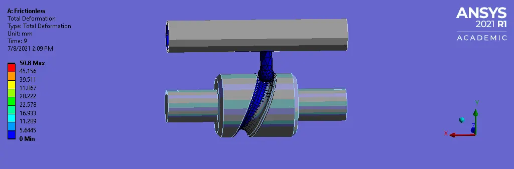
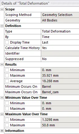
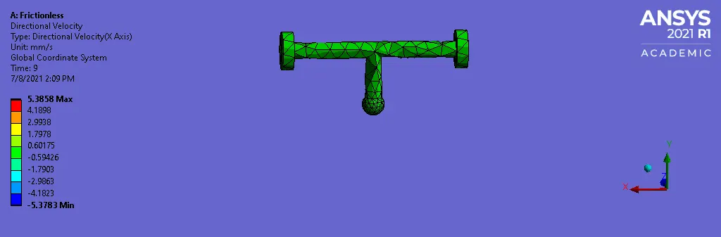
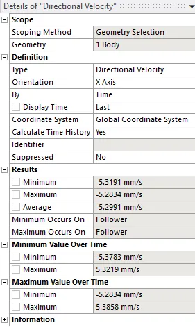
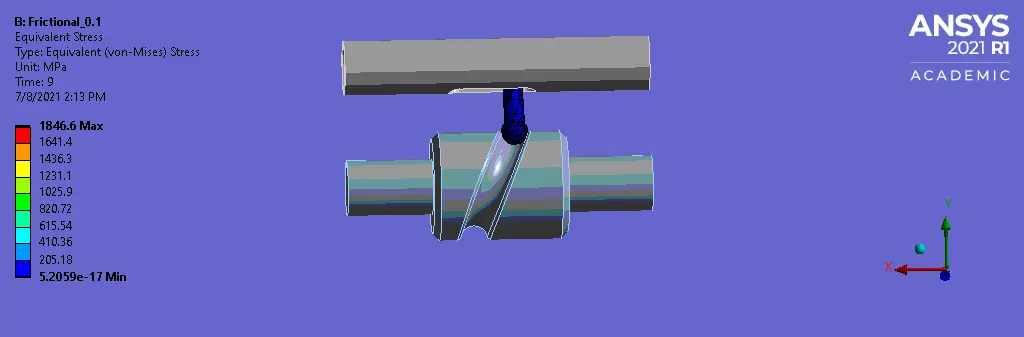
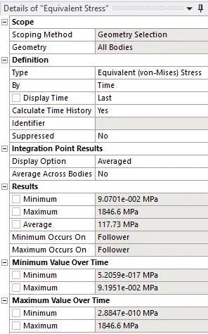
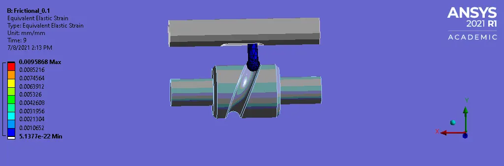
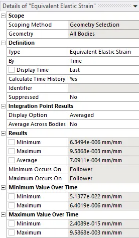
- Case 2 – Frictional – 0.1
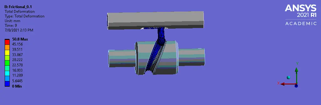
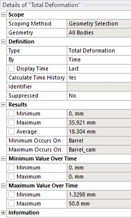
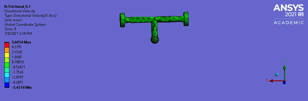
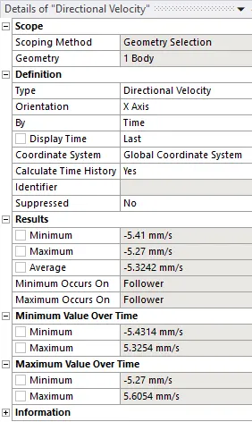
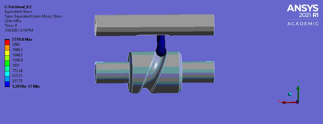
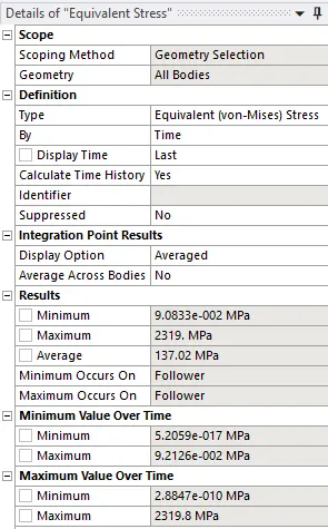
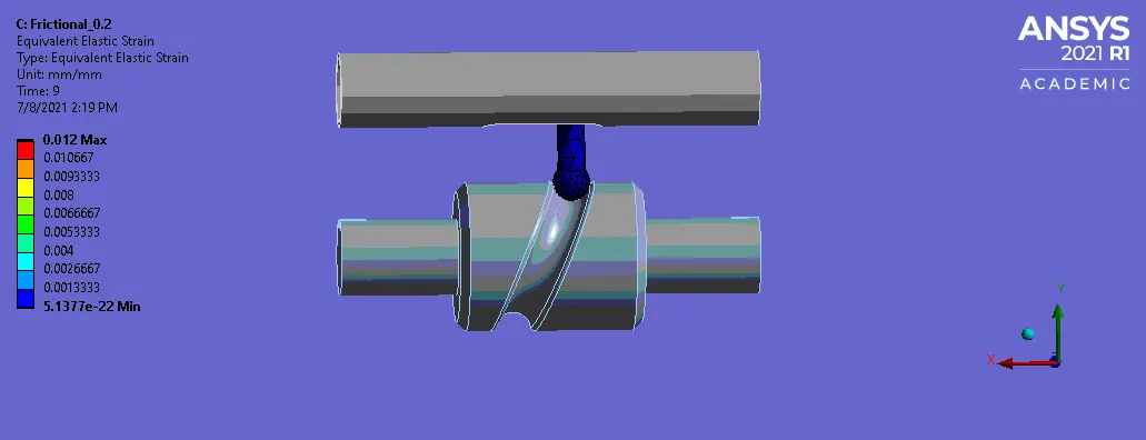
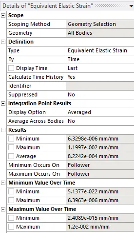
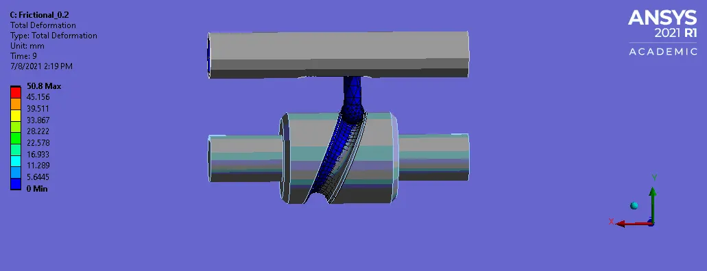
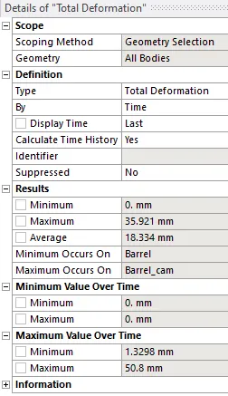
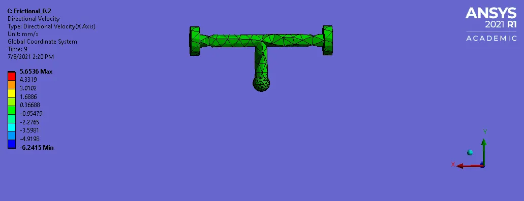
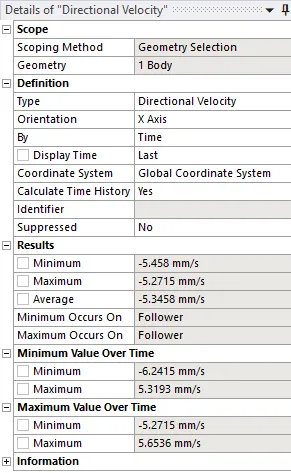
- Case 3 – Frictional - 0.2
COMPARISON TABLE:
| Stress (Mpa) | Strain | Deformation (mm) | Velocity (mm/s) | |
| Case 1 | 1756.6 | 8.8296e-3 | 35.921 | 5.2834 |
| Case 2 | 1846.5 | 9.5868e-3 | 35.921 | 5.27 |
| Case 3 | 2319 | 1.1997e-2 | 35.921 | 5.2715 |
- Here, we can observe that the stress developed in Frictionless is less than the stress developed in the Frictional contacts.
- The deformation is observed to be constant.
- There is also slight change in the velocity of the follower.
- The results vary as the contacts are changed to friction and also when the friction coefficient values is increased.
- As friction acts, more stress is developed and velocity of the follower is reduced as friction resists the movement of follower for some value.
LEARNING OUTCOMES:
- To setup transient structural analysis
- To assign material from the material library.
- To define contacts for the barrel, barrel cam and follower.
- To define joint loads.
- To define rotation for barrel cam.
- To deploy mesh on the geometry.
- To define output results.
CONCLUSION:
- By performing this project we conclude that the Transient analysis of Long piston and cam model is performed and the directional velocity .results are obtained.
MODEL LINK:
https://drive.google.com/file/d/1XSmzUrxqJwiuOdtSQnJxLoS7kYdQ7y61/view?usp=sharing