Week 7-Long Piston With Cam
- Objective: To perform transient analysis on a piston and cam mechanism model for the given cases:
- with Frictionless Contact
- with Frictional contact with μ =0.1
- with Frictional contact with μ =0.2
- Procedure:
Open the transient structural analysis system in the Project schematic. The material used for the analysis is structural steel which is available in the material library. Now proceed to import the geometry.
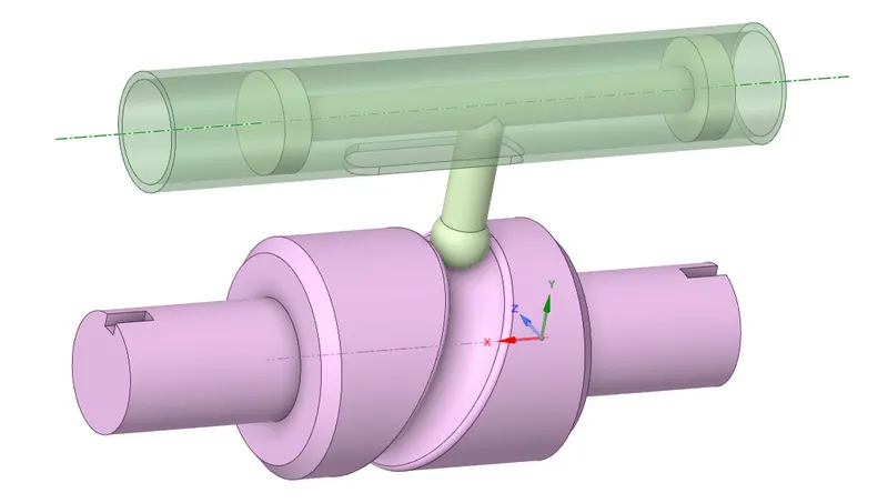
Import the Geometry. Open the Geometry in SpaceClaim. Ensure the geometry is properly imported by doing quick visual inspection. The geometry is properly imported as observed below:
Update and open the mechanical module. The stiffness behavior for the barrel and cam follower is set to rigid. This will consider them as point mass concentrated on body centre. Now define the contact
between the Follower and the Cam, and the Follower and the Barrel. Frictionless type of contact is defined.
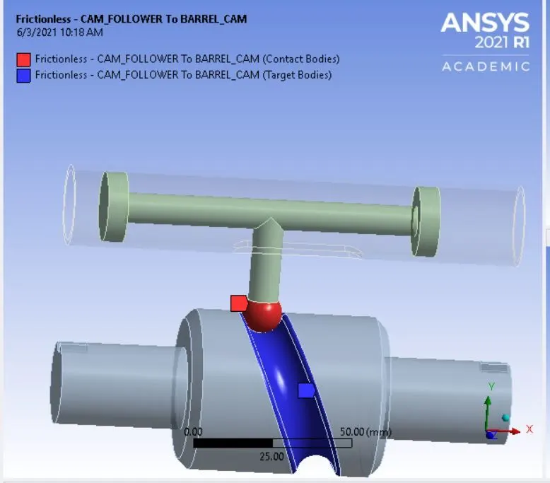
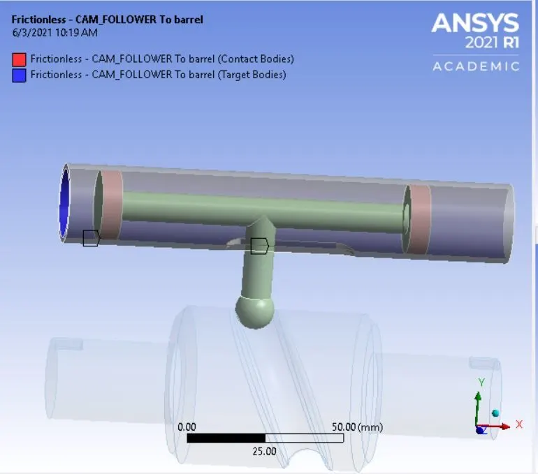
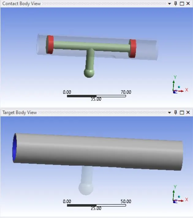
The cam is supposed to rotate so that the follower will translate accordingly in the fixed Barrel. Insert Fixed joint to fix the Barrel. Go to Connections >Insert > Joint. Select the Connection type as Body Ground
and type as Fixed. Select the outer surface of the barrel to fix it.
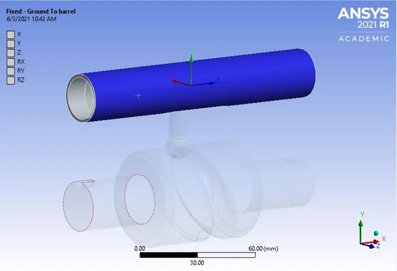
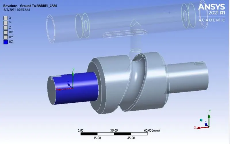
To rotate the cam, insert a revolute joint. Go to Connections > Insert > Joint. Select the Connection type as Body Ground and type as Revolute. Select the outer surface of the cam shown below:
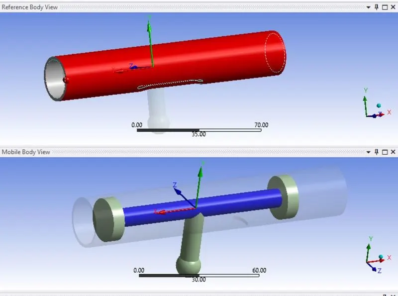
The follower is supposed to translate in the barrel as the Cam rotates. Insert Body-Body joint with type as Translation. Here, Barrel is the reference body in which the Follower will translate. In the reference
body, select the outer surface of the Barrel and in the mobile geometry scope, select the follower surface as shown below:
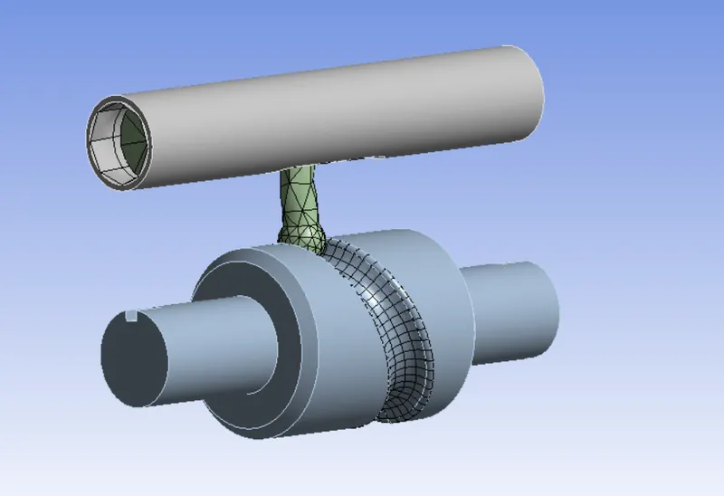
Mesh size of 3 mm is used in the contact region between the cam and the follower ball using mesh sizing.
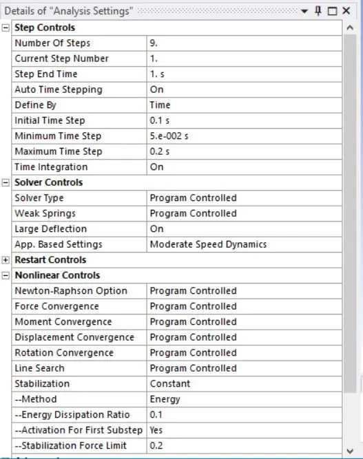
The analysis is to be completed in 9 steps. Go to Analysis settings and enter no of steps = 9. For the 1st time step, following settings are defined:
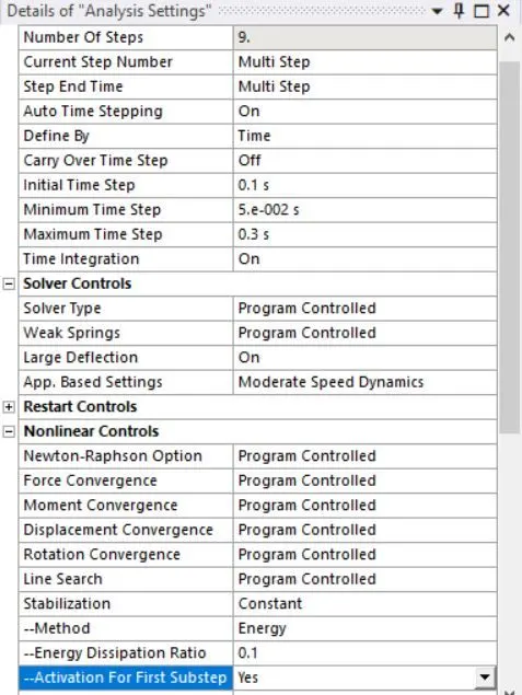
For the remaining time steps, following analysis settings is used:
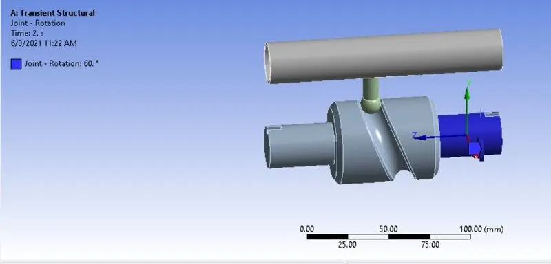
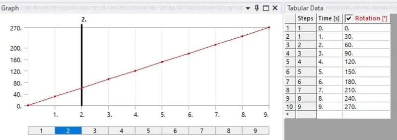
Now insert the joint load for rotation of the cam. Go to Transient > Insert > Joint load. Select the Body to Ground revolute joint. Select type as rotation and enter the magnitude in tabular form as shown below:
The case setup is now completed. List the required results, and run the simulation.
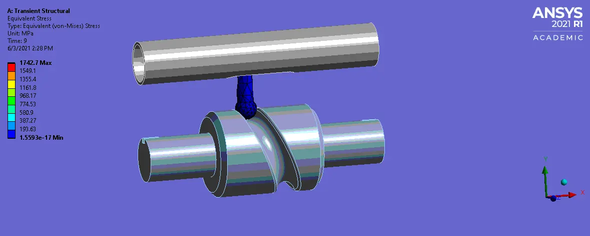
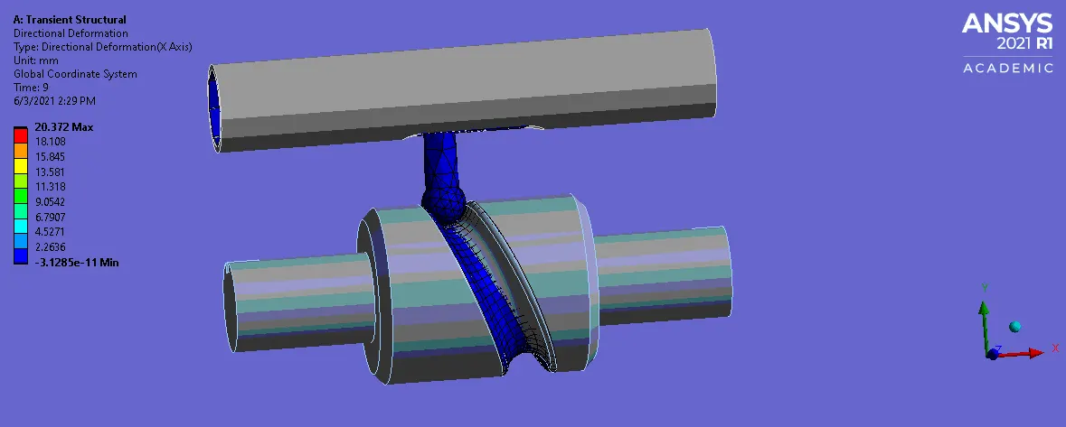
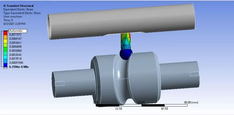
- Results: Case 1 with Frictionless contact:
Equivalent stress contour:
Total Deformation:
Equivalent Strain:
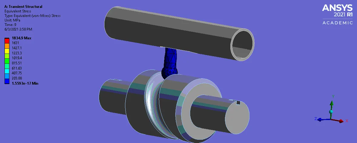
- Case 2: Frictional contact with μ =0.1
Stress in the follower:
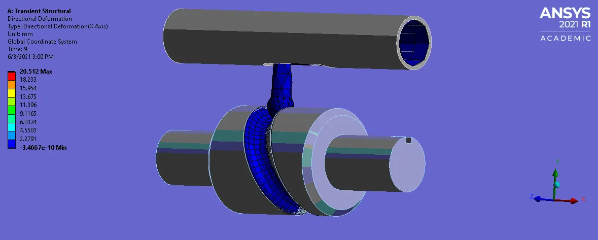
Total deformation:
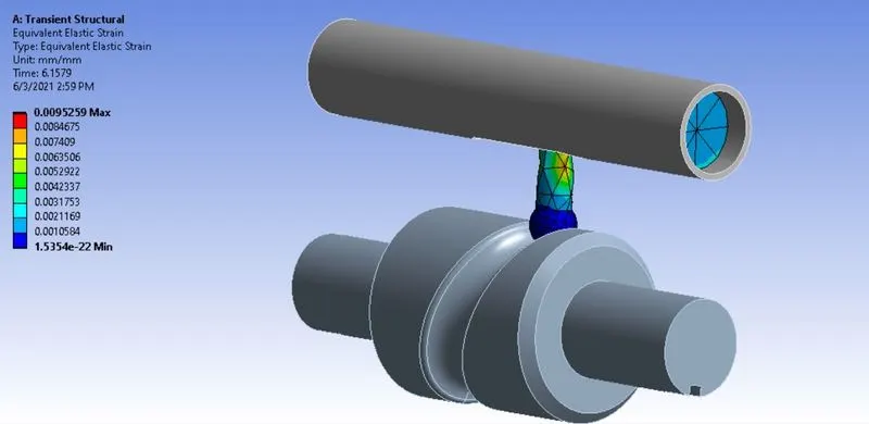
Equivalent strain:
- Case 3: Frictional contact with μ =0.2
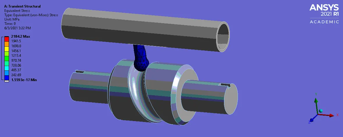
Stress in the follower:
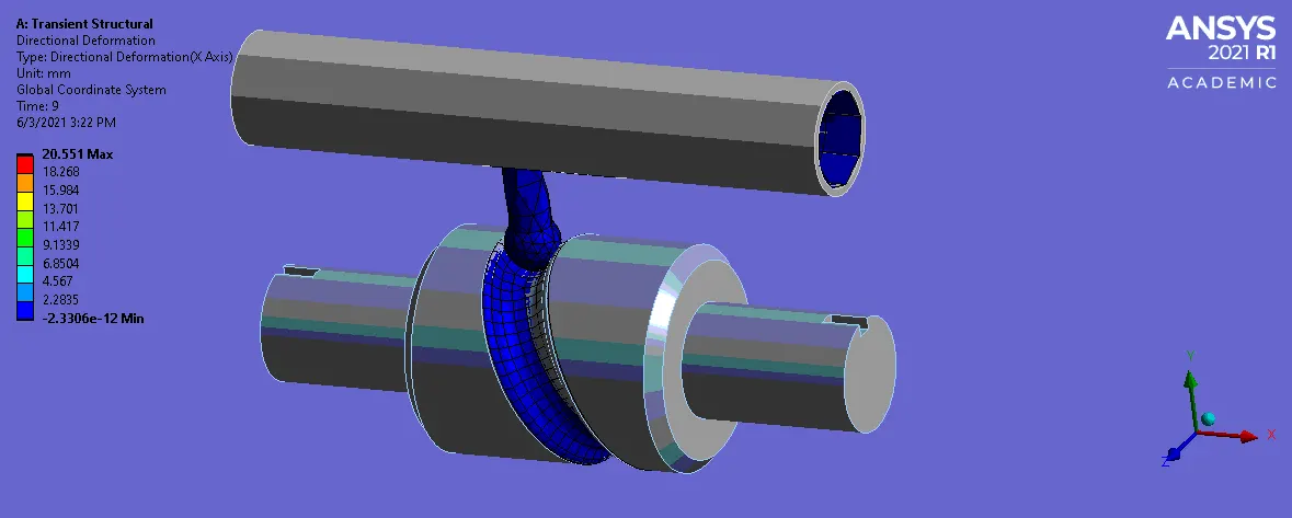
Total Deformation:
Equivalent strain:
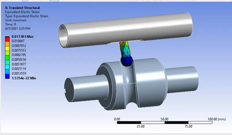

As seen above, the total deformation is almost same for all the cases. However, it is observed that the stress observed is least for the Frictionless contact. For Frictional Contact, as friction coefficient increases,
increase in Equivalent stress is observed. As friction coefficient increases, more force is required to move the follower, hence the increase in stress is observed.
- Conclusion: Thus the given challenge is successfully simulated and the results are compared.