Pedestrian Head Impact with Car's Hood using LS-DYNA
INTRODUCTION
Investigation of a pedestrian accident with a car is part of checking pedestrian safety. Experimentally, it is investigated by performing an accident onto an anthropomorphic test device (ATDs), also called a dummy, and seeing the scenario with 100s of cameras. Companies’ all-over the world follow global technical regulation (GTR) No. 9, to reduce the level of injury to the pedestrian during an accident. The level of injury to the pedestrian is checked by AIS (Abbreviated Injury Scale). It is a measurement tool or a coding system that represents the threat to life associated with the injury. The GTR 9 collects its information from numerous sources spread globally. According to it, a crash speed of 40 kmph covers more than 75% of total pedestrian injuries, in all regions. The International Harmonized Research Activities (IHRA) data indicated that bonnet contacts caused 41% of child head injuries of AIS2+ and 19% of the adult AIS2+ head injuries. The AIS2+ involves concussion with or without skull fracture, loss of vision, and/or cervical fracture.
In this work, a child head form model was taken as a model to check the severity of the accident on the head model. As a part of studying the software, the simulation was not directly solved using the head form model and the bonnet, instead, in the first case, a sphere model was impacted with a rigid wall, in the second case, the head form was impacted with the rigid wall, and in the third case, the head form was impacted with hood.
CASE 1: IMPACT OF A SPHERE WITH A RIGID WALL
In case 1, a sphere model was imported into the LS-Dyna GUI, and a rigid wall was created, to strike the sphere model against the rigid wall, as shown in the figure below.
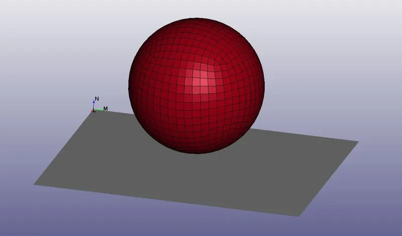
Figure 1: A sphere model, representing the head, against a rigid wall.
L. Vool et al. [2] have created a finite element model of the human head. They have collected the material data for the scalp, the skull, the brain, etc. It is observed that in many works, the hyperelastic material is used for material modeling for the head. However, it is also observed that the material is assumed isotropic in many works, and no clear data is yet available for material modeling of the head. To keep the work simple, at the initial stage, an elastic material (001_ELASTIC) was used with the value of young’s modulus, density, and Poisson’s Ratio as used in [2].
Young’s modulus = 6*10e6 kPa = 6000 MPa
Density = 1400 kg/m^3 = 0.0014 gm/mm^3
Poisson’s Ratio = 0.22
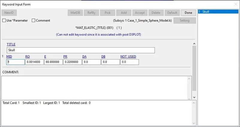
Figure 2: Material card for assigning the skull material data to the sphere model.
This is how a sphere model was used with the material of the skull applied to it. Then, a section card was also created to define the element as a shell with a thickness of 2 mm. After, creating the material card, and the section card, it was then assigned to the sphere model. A contact card was created to assign AUTOMATIC_SINGLE_SURFACE contact to the sphere model, as that was the only model in the GUI which could deform. To assign it, firstly, a node-set of the sphere model was created and then using Model and Part → Keyword Manager → All → CONTACT → AUTOMATIC_SINGLE_SURFACE, the contact card was created.
Now, according to GTR No.9, a crash speed of 40 kmph covers more than 75% of total pedestrian injuries, in all regions of the world. So, this velocity was considered in the complete work. To the sphere model, the initial velocity of 40 kmph, or 11.11 mm/s was applied, in the direction of the rigid wall.
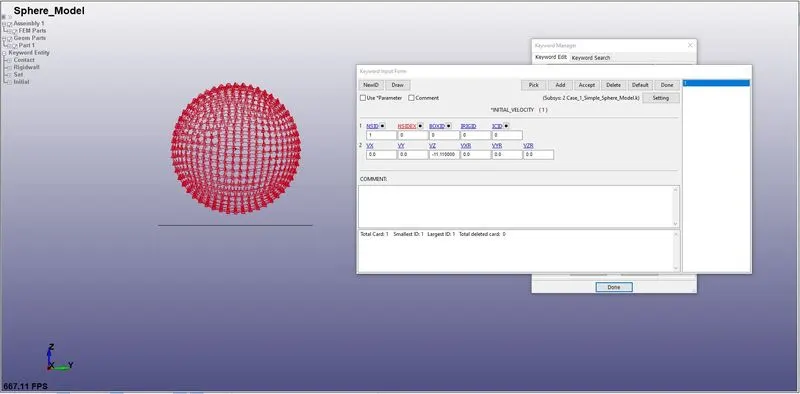
Figure 3: Initial Velocity of 11.11 mm/s applied to the sphere model.
After done with all the physics that was required to apply, then the solver setup was required. Using the CONTROL_TERMINATION card, the simulation was set up for 2 seconds. Using, DATABASE_BINARY_D3PLOT, the frames of resulting contours were called each 0.01 secs. Using DATABASE_HISTORY_NODE, some nodes were selected for getting the node history. Then, using DATABASE_ASCII_option, NODOUT was called to activate the DATABASE_NODE_HISTORY. Also using DATABASE_ASCII_option, GLSTAT and RCFORC were called to get the energy data and the contact force-related data, respectively.
Post-processing
The model was then solved, and the d3plot file was opened to check the contour. The below figure shows the isometric view of Von Mises contour of the sphere model at 3 ms.
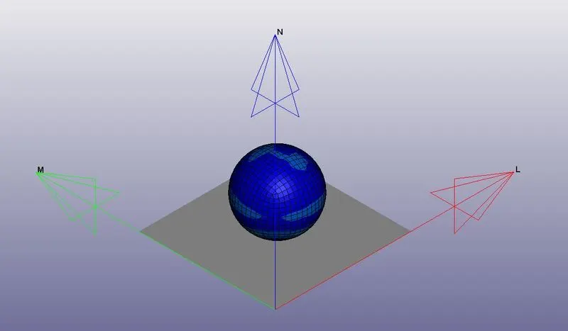
Figure 4(a): Isometric view of Von Mises contour of the sphere model.
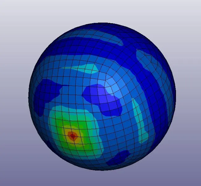
Figure 4(b): The bottom portion (in contact with the rigid wall) of the sphere model.
Now, the primary result that was required to check was the HIC (or Head Injury Coefficient/Criterion). HIC is a parameter used to measure the level at which the head could injure. It is derived from the acceleration data, for the short duration of time, when the acceleration is at its peak. Typically, the peak acceleration lasts for less than 36 ms. But in this case, the hic15 parameter was used to save time. The figure below shows the hic15 result. In this case, the hic was calculated for the particular node, however, when the actual head form model is taken into the simulating environment, the case is different. In that case, the hic is calculated on the accelerometer only.
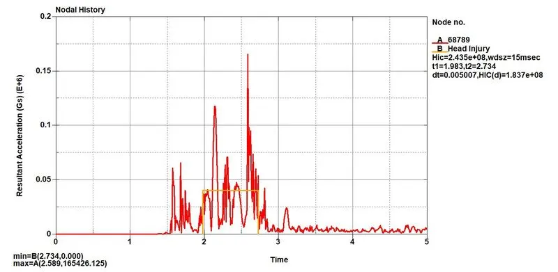
Figure 5: Resultant acceleration vs. time plot with HIC scale (unclear).
In the figure above, the HIC scale can be seen covering the area with an orange border. The difference between t2, & t1can be observed less than 15 ms. Figure 6 was obtained from the source [4]. (It may be subject to copyright). The HIC value is 2.435e+08. From the fig. 6, it can be seen that the probability of injury is very high. Thus, the sphere model can be assumed very risky against the strike.
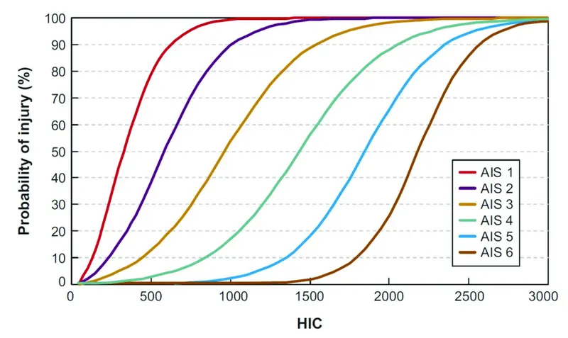
Figure 6: Probability of Injury (%) vs. HIC plot.[4]
CASE 2: IMPACT OF A HEADFORM WITH A RIGID WALL
In the second case, the child head form model was used. Also, it was rotated by 45 degrees. The head form model of the child was prepared by some organizations like Humanetics or LSTC. The changes in the model are not at all recommended. The model can only be referred to some problems. To rotate and refer to the model in this work, firstly, a .k file was created in which the *DEFINE_TRANSFORMATION card was included. This card is used to define the degree of rotation. The orientation of 45 degrees was given. It is because it is an observation of some organization that head hit the hood in 35-75 degrees of range of angle.
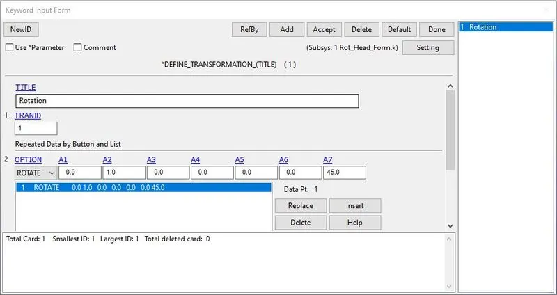
Figure 7: DEFINE_TRANSFORM card.
Now, to apply that rotation to the head form model, *INCLUDE_TRANSFORM card was used. In this card, the FILENAME is given as the name of the file name of the head form model, and TRANID is the card id of the transformation that was created just before. The TRANID can be seen in fig. 7. This is how, no modification is done in the original head form model, and just the orientation of it is changed in the separate file, in which it is referred.
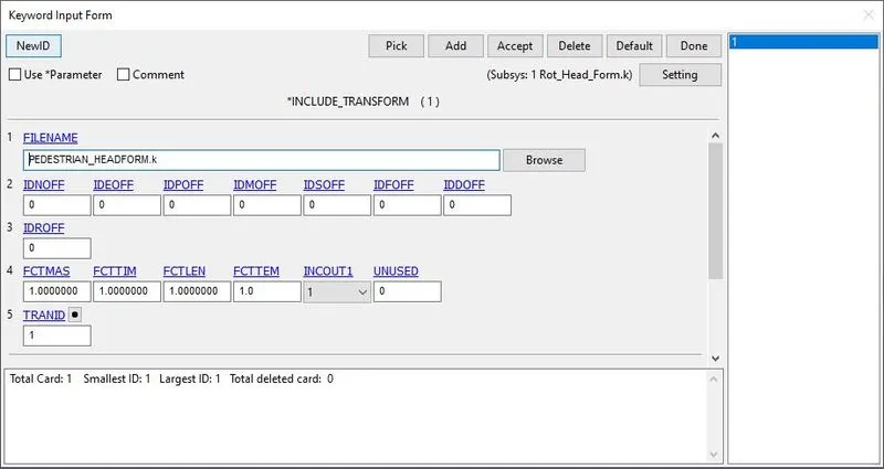
Figure 8: *INCLUDE_TRANSFORM card.
When another file was opened, in which the head form model was referred with 45 degrees of orientation, the oriented head form was found as shown in the figure below. As can be seen in the figure, the model is oriented by 45 degrees to the global XY plane.
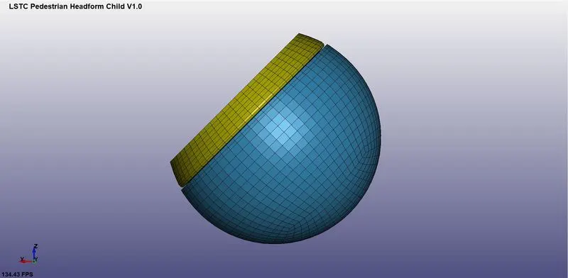
Figure 9: Head form model oriented in 45 degrees to the global XY plane.
It was required to simulate this model like a child's head hit the hood of a car during an accident, a rigid wall was required. In this second case, instead of a hood, a rigid wall was tried to understand the procedure of performing the simulation. A rigid wall was created perpendicular to the global z-axis.
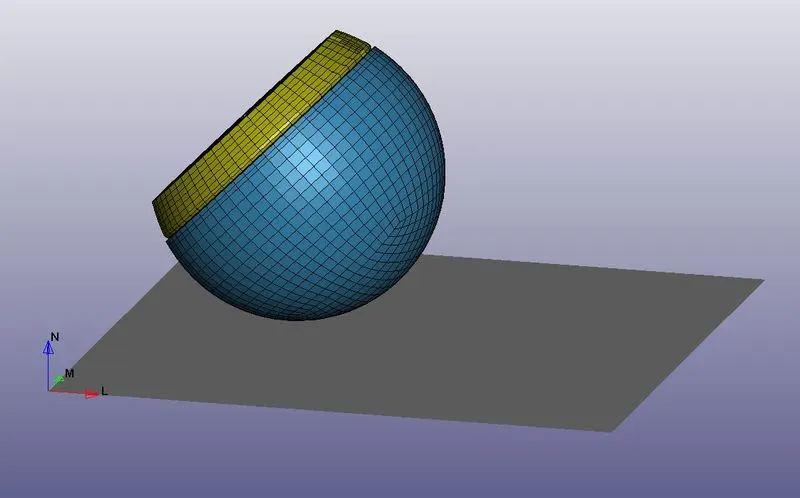
Figure 10: Head form model with the rigid wall against it.
The next essential part of preprocessing was to define the material, the section, and the contact. Now, as no modification is recommended with the head form model, all of these cards were defined by the provider itself.
Next, the initial velocity had to be given to the model. The linear velocity of 40 kmph or 11.11 mm/ms had to be given. But because the model was oriented at 45 degrees, the components of velocity were required. Thus, the velocity of 11.11*(cos45º) would act in both x- and z-axis.
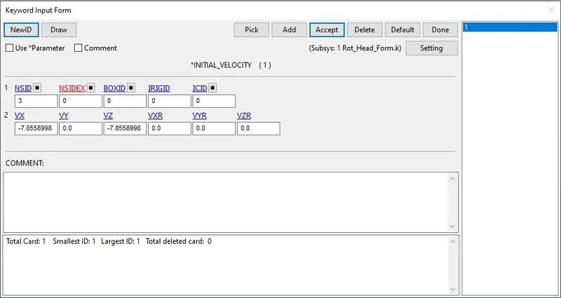
Figure 11: Initial velocity given to the head form model.
After creating the rigid wall, and defining the model with an initial velocity, *CONTROL_TERMINATION card was created to end the simulation at 5.5 ms. The binary d3plot file was requested. Along with it, using DATABASE_ASCII_option, GLSTAT, NODOUT, and RCFORC was also requested to get the energy data, node history, and the contact force data.
Post-processing
The figure below shows the Von Mises contour of the simulation when the head form model hit the rigid wall. The head form model can be clearly seen squeezed, due to an impact.
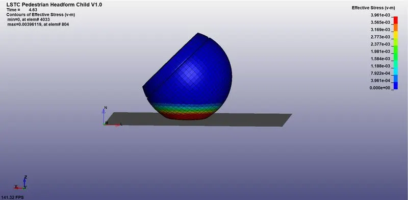
Figure 12: Von Mises contour of the head form model, when it hit the rigid wall.
The severity of the injury can better be illustrated by HIC. Thus, the resultant acceleration vs. time plot was drawn, to find out the HIC. In this case, unlike the first case, the acceleration is checked on the accelerometer only. Thus, the results below are the result obtained by the accelerometer tool.
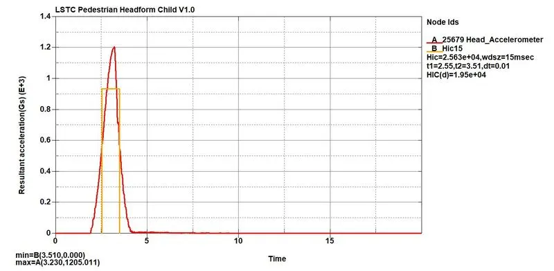
Figure 13: Resultant acceleration vs. time plot with HIC15, for case 2.
In fig. 13, the difference between t1 and t2 was 0.96 which is less than 15 ms. The HIC value can be seen as equal to 2.563E+04. It is a very huge value to consider. It indicates that there is a huge risk of severity of damage with AIS 6. But this shouldn’t happen in a real-time scenario, because, in practical cases, the hood of the car is deformable, and generally a free space is kept beneath it to let it deform. Thus, it contributes to absorbing the energy, and the severity of damage reduces.
It was also found that when the upper skin part was deformed by approx. 35 mm, the skull was not at all deformed. Only the scalp region was deformed, and thus the skull remained safe.
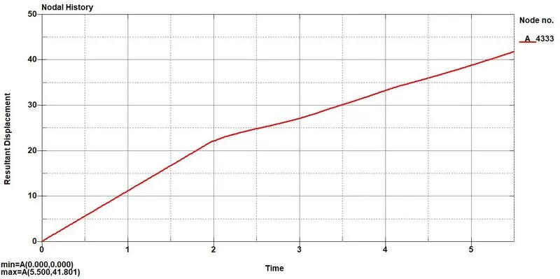
Figure 14: Resultant Displacement vs. time plot for the node in the deformed region.
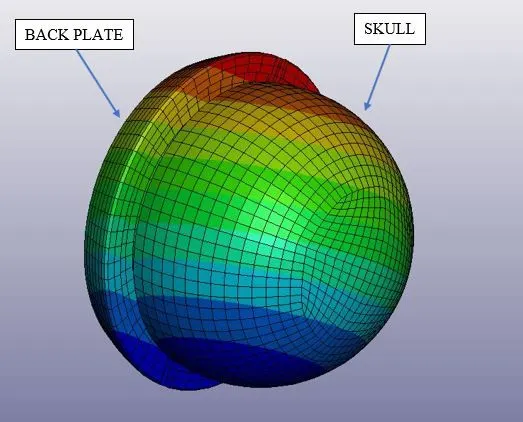
Figure 15: Skull part beneath the skin part.
CASE 3: IMPACT OF A HEADFORM WITH A HOOD OF A CAR
In case 3, again some more complexity had to include. Now, the head form model was to hit with the actual hood model. In case 2, the head form model was included in the simulation file, without disturbing the original file of the head form model, by using the syntax *DEFINE_TRANSFORMATION, and *INCLUDE_TRANSFORM, in the blank file. In case 3, the only change that had to do was that instead of a blank file, those two-syntax had to make use in the keyword file of the hood model. So, a hood model had to open, and similar to case 2, *DEFINE_TRANSFORMATION, and *INCLUDE_TRANSFORM had to include in it. These two cards can be seen in fig. 7, and fig. 8.
The file when saved (with a different name), closed, and re-opened, the head form was seen included in the file, appearing as shown in the figure below.
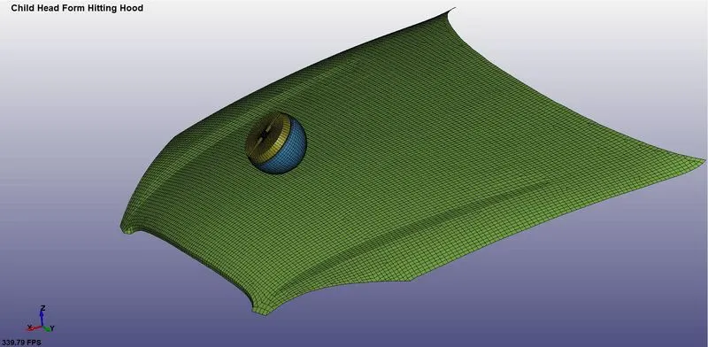
Figure 16: The child head form model file included with the hood model file.
The next essential is to define the material and the section. The head form model was already defined with the material, and the section, by the LSTC organization. So, only the model had to define with the material and the section. For the hood model, it was defined with the elastic-plastic card, with the property of aluminum material.
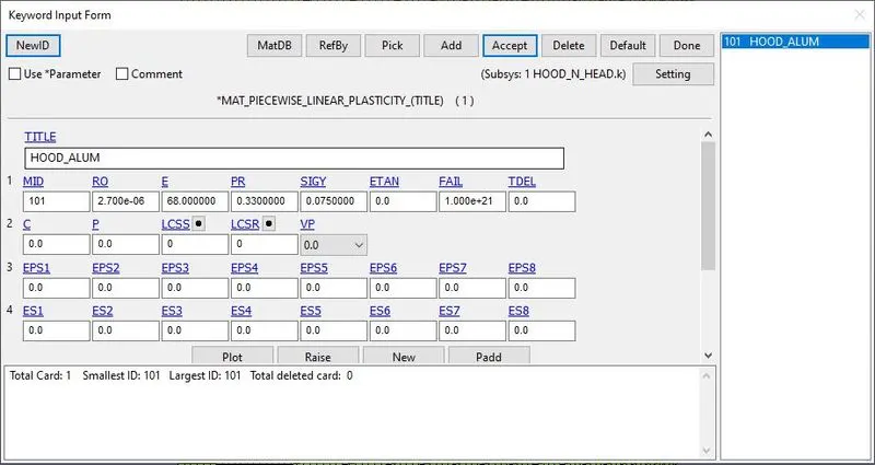
Figure 17: Elastic-plastic material card assigned to hood with the property of aluminum material.
Then, a section card was created for the hood model, and given it the thickness of 2 mm, with 5 integration points.
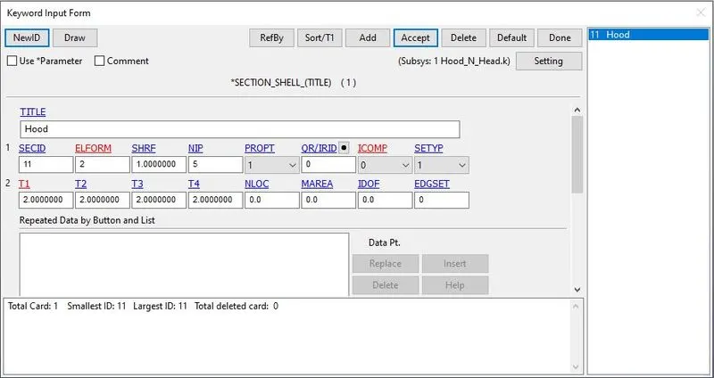
Figure 18: Section card for the hood.
When the head form model would hit the hood, two types of contacts would take place. One would be the contact of the head form model with the hood, and the other would be the contact of the head form with itself. The second contact i.e., the contact of the head form with itself, was taken care of by LSTC. The remaining was to create the AUTOMATIC_SURFACE_TO_SURFACE contact between the head form model, and the hood.
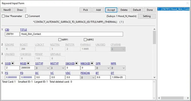
Figure 19: AUTOMATIC_SURFACE_TO_SURFACE contact for the hood and the skin of the head form model.
In the boundary condition, the initial velocity had to provide to the head form, similar to case 2. Thus, the velocity of 11.11*(cos45º) i.e., 7.856 mm/ms was given to it, in x-, and z-axes.
After creating the rigid wall, and defining the model with an initial velocity, *CONTROL_TERMINATION card was created to end the simulation at 5.5 ms. The binary d3plot file was requested. Along with it, using DATABASE_ASCII_option, GLSTAT, NODOUT, and RCFORC was also requested to get the energy data, node history, and the contact force data.
Post-processing
The figure below shows the Von Mises contour of the simulation when the head hit the hood at 4 msec. From fig. 20 (a), (b), and (c) it can be seen that, although there is some amount of stress on the head, it was only 3.779E-03 MPa at 12 msec after the head hit the hood. On the other side, the hood had maximum stress of 7.500E-02. Because the hood was defined with lightweight aluminum material, it helped in not letting the stress go into the head part, and it itself absorbed a large amount of energy. It also occurred like that because the head was a stiffer part than the hood.
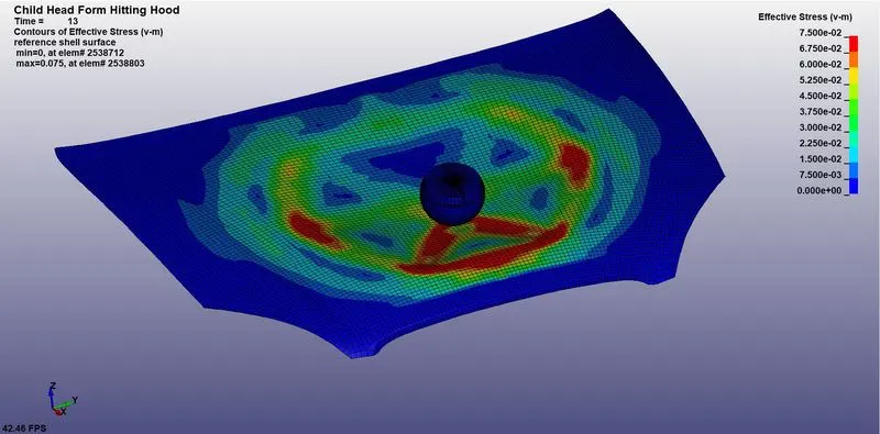
Figure 20(a): Von Mises contour of the simulation when the head hit the hood at 4 msec.
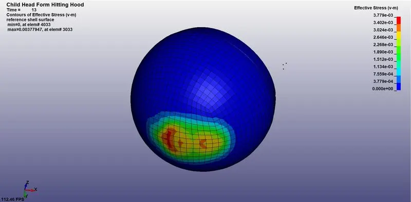
Figure 20(b): Von Mises contour of the head when it hit the hood at 4 msec.
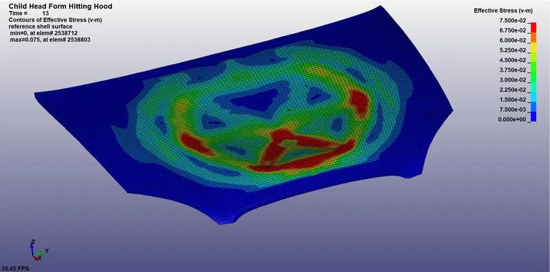
Figure 20(c): Von Mises contour of the hood when the head hit it at 4 msec.
The major concern in post-processing was to check the HIC. Thus, the resultant acceleration vs. time plot was drawn along with hic15. It appeared as shown below.
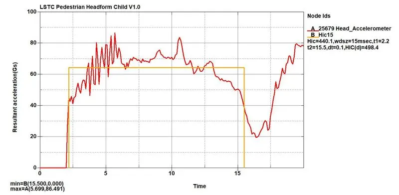
Figure 21: Resultant acceleration vs. time plot with HIC, for case 3.
In fig. 21, it can be clearly seen that the value of HIC on the accelerometer of the head was 440.1, which is very less than case 1, and case 2. It occurred because of the introduction of deformable parts i.e., hood, which helped in absorbing the most amount of energy. Referring to fig. 6, when this value is compared, it was found that, with 40 kmph of speed at 45º inclination, when the head of the child hit the cars aluminum hood, there is a 60% probability of damage with level AIS1, 20% probability of damage with level AIS2, 7-8% probability of damage with level AIS3, 2-3% probability of damage with level AIS4, and the level of damage with AIS 5, and AIS6 is negligible.
CONCLUSION
This work was explicitly carried out to learn the procedure of carrying out the head impact analysis. However, many conclusions can be drawn from this work. In case 1, the HIC was 2.435E+08, and in case 2 it was 2.563E+04. In both the cases, the similarity was that the rigid wall was used in both the cases, and the difference was that the sphere model of case 1 hit the rigid wall perpendicularly with 40 kmph of initial velocity, and in case 2, the head form model hit the rigid wall with an inclination of 45º at 40 kmph of the initial speed. Another difference was that in case 1, elastic material with skull material property was used, however, in case 2, the material for the head form model was pre-defined with rubber material. In both cases, due to the presence of the rigid wall, the HIC was very high. However, in case 2, when the rigid wall was replaced with the hood model with aluminum material property, the HIC was significantly reduced. And the clear conclusion could be drawn from the HIC value of the results. In case 3, it was found that the probability of severe damage to the head is quite less.
References
[1] https://unece.org/fileadmin/DAM/trans/main/wp29/wp29wgs/wp29gen/wp29registry/ECE-TRANS-180a9e.pdf
[2] Voo, L., Kumaresan, S., Pintar, F. A., Yoganandan, N., & Sances, A., 1996, Finite-element models of the human head, Medical & Biological Engineering & Computing, 34(5), 375–381.
[3] Falland-Cheung, L., Waddell, J. N., Chun Li, K., Tong, D., & Brunton, P., 2017, Investigation of the elastic modulus, tensile and flexural strength of five skull simulant materials for impact testing of a forensic skin/skull/brain model, Journal of the Mechanical Behavior of Biomedical Materials, 68, 303–307.
[4] Hayes, Wilson & Erickson, Mark & Power, Erik, Forensic Injury Biomechanics, 2007, Annual review of biomedical engineering, 9, 55-86. 10.1146/annurev.bioeng.9.060906.151946.