PROJECT-1 Head Impact (LS - DYNA)
HEAD IMPACT
AIM:
To perform the analysis of head impact and calculate the HIC (Head injury criteria/coefficient) Value:
Case 1 : Simple-head and rigid wall
Case 2: Head foam and rigid wall
Case 3: Head foam and meshed hood
INTRODUCTION
HEAD INJURY CRITERIA(HIC)
Efforts to decrease the losses in human lifes on the roads during fifties led to an increased research into the biomechanics of head impact. A break-through was made with the introduction of the Wayne State Tolerance Curve. This curve was interpreted and a weighted injury criterion was developed. This criterion was later transformed into the Head Injury Criterion (HIC) and used in a proposed legislation to improve the crashworthiness of cars. Although heavily criticized the HIC-criterion still is the most established method to assess head injury in automotive impact conditions.
When the vehicle is engineered, manufacturers must ensure that any vehicle variant selected by the testing body is able to meet the required safety criteria. Consequently, as it is impossible to compute all the occupant injury responses for all vehicle structure manufacturing tolerance variants, a more statistical approach is usually used in order to encompass all eventualities. Some OEMs use a 6-Sigma approach for their vehicle design targets and ensure that all internal certification tests lie within 3σ (standard deviations) of the legal target. These OEM internal targets are kept confidential and vary from one OEM to another.
To add to the challenge of optimizing vehicle safety structures, the computation does not often exactly predict the ‘exact physical’ crash test “values”. A vehicle impact usually involves high strains due to the speed of structural deformation as well as the large deformations related to the dissipation of kinetic energy. Impact events vary during the time domain, leading to the transfer of forces, structural displacements, and therefore energies through the structure. Some complexity is added by the fact that damage is generated during the event; components’ response is changing during the impact due to atomical changes caused by structural collapse. A typical example would be a metallic vehicle crush can that during the impact would start to plastically deform and catastrophically buckle leading to an uneven transfer of force inside the vehicle structure. This damage may also mean that some masses can detach having the effect of un-coupling some vehicle structural and ancillary masses during the accident, causing complex and unidentified outcomes. This example is common in vehicle impact scenarios; as such the problem that the engineers are faced with is a time-dependent nonlinear problem.
Consequently, other design and therefore optimization targets need to be set which should include the prediction “mismatch” between CAE and the corrected mean to the legal tests adjusted with the 6-sigma method. A hypothetical example is presented in below table to illustrate the difficulty in design optimization which starts by setting an adequate CAE target. This example is based on occupant head injury.
Table 1.3. A HIC Legal Target That Has Been Offset for Design and CAE (Hypothetical Example)
| Legal Requirement | 6-Sigma Method for Robust Vehicle Legal Delivery (Test) | CAE Design Target | |
|---|---|---|---|
| Head injury criteria (HIC) | 1000 | 800 |
750 |

Head injury criteria for free motion head form (HIC(d))
In the case of a surrogate head impactor, as in the case of the Interior Head Impact legislation (FMVSS201), HIC(d) is used and computed as Equation
HIC(d)=0.75446⋅HIC+166.4
CASE1: SIMPLE HEAD AND RIGID WALL
Procedure
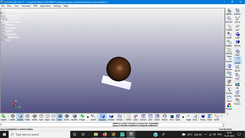
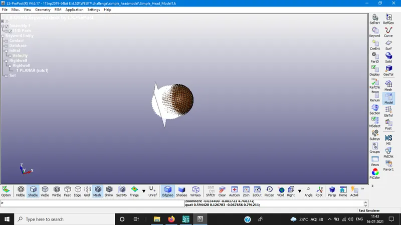
- The simple head is imported with pre-meshed elements.
- Rigid wall create opposite to the head model i.e., normal to the z-axis
SECTION:
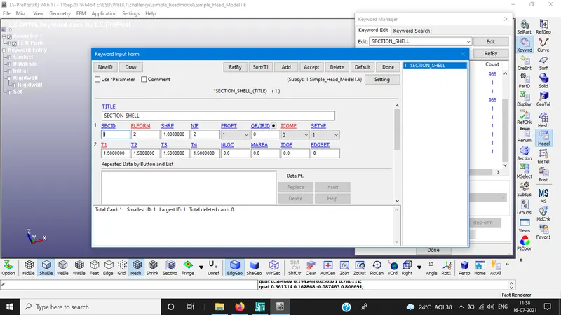
section creation defines section properties for the elements types.
Section ID is referred to part ID card
T1 thickness shell = 1.5mm
MATERIAL:
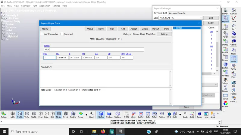
Material card is is used to define the model for the head foam.
BOUNDARY CONDITIONS:
Here initial velocity is assigned for head foam to impact the rigid wall
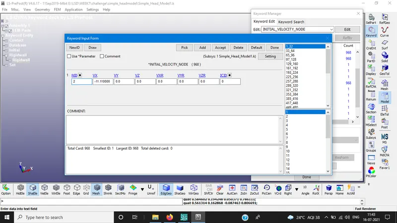
We assumed initial velocity is 40kmph(11.11mm/ms) in the negative X-axis towards the rigid wall.
CONTROL AND DATABASE CARDS:
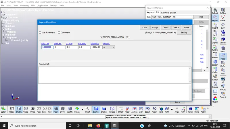
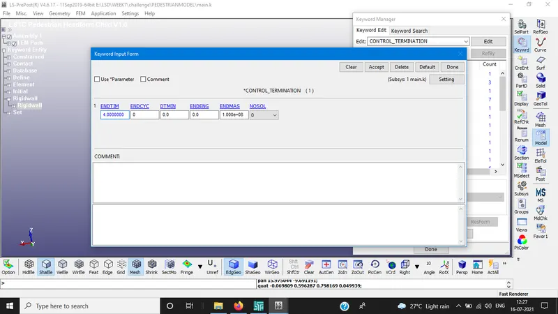
Control Termination is defined at(simulation ending time) 5ms.
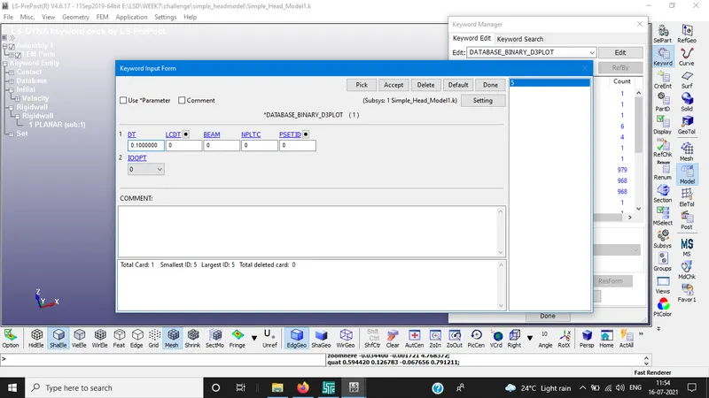
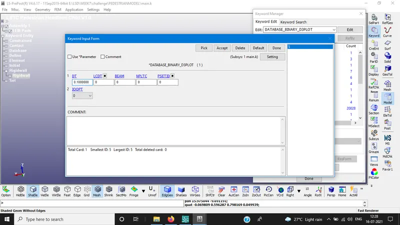
BINARY D3_PLOT: It defines the frequency at which animation file is created.
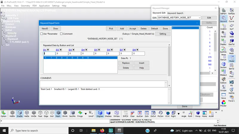
ASCII OPTIONS
GLSTAT, MATSUM, NODOUT, RWFORC are activated.
CONTACT CARD:
In order create a collision surface to surface is created between rigid wall and head foam.
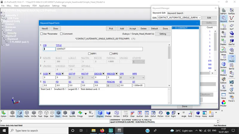
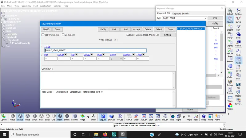
PART ID ASSIGNING
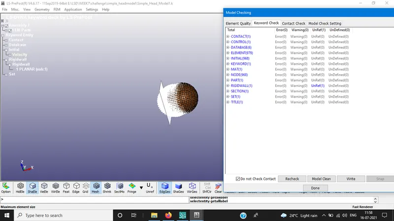
MODEL CHECK
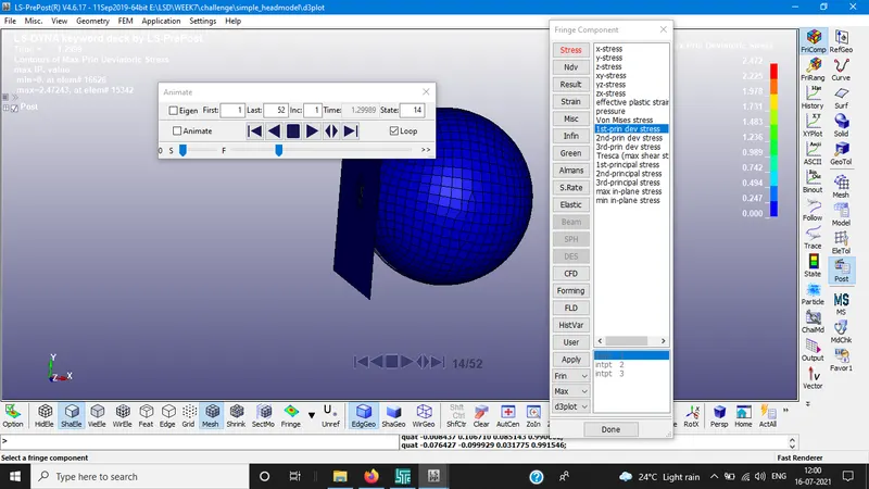
RESULTS
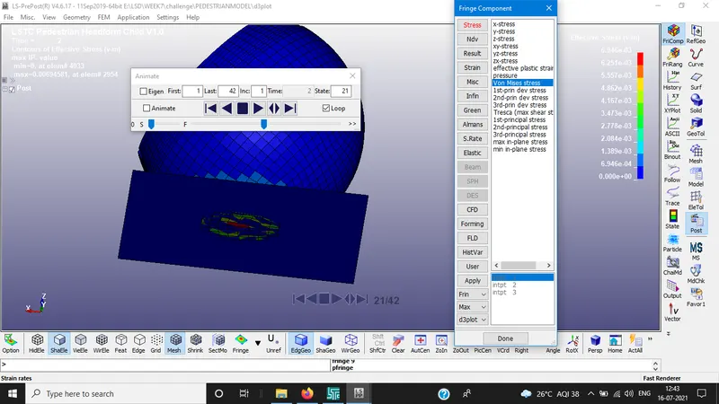
STRESS VALUE:
VON-MISES STRESS: 2.47Gpa
GLSTAT:
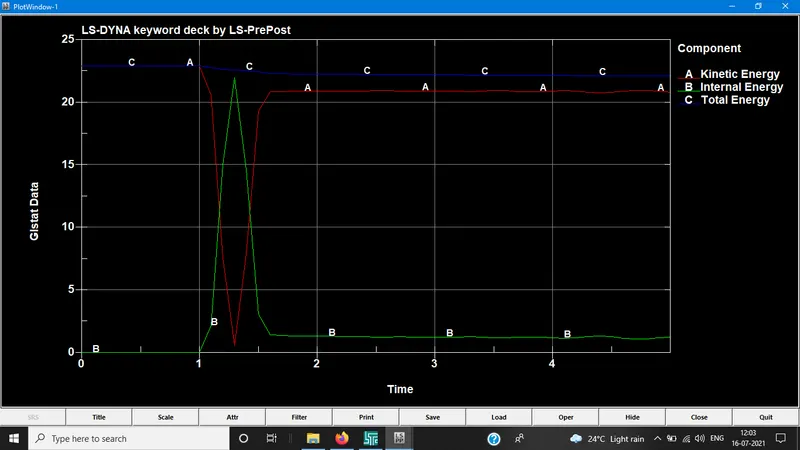
MATSUM:
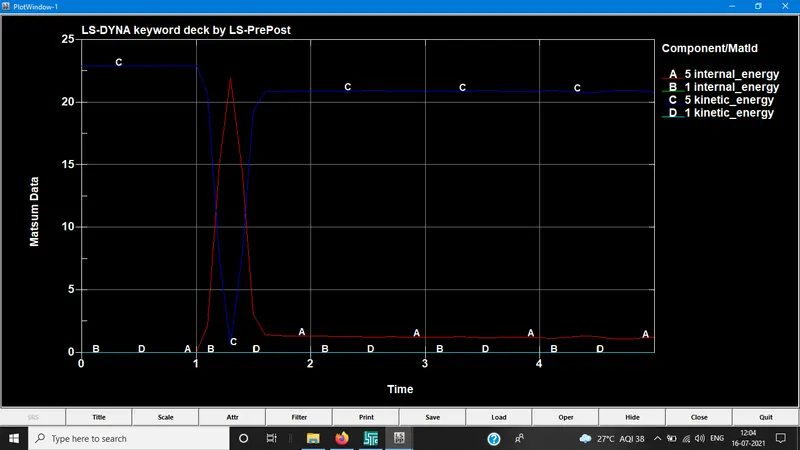
NODOUT:
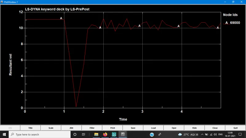
RWFORC
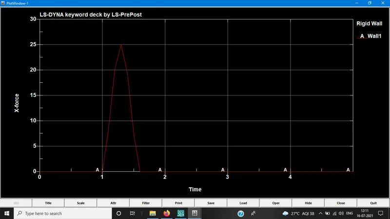
CASE2: CHILD HEAD FOAM AND RIGID WALL
The release angle of head is 50 degrees. The head foam velocity impact is at 11.11ms/ms(40Kmph).
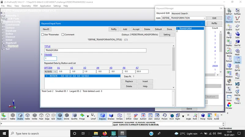
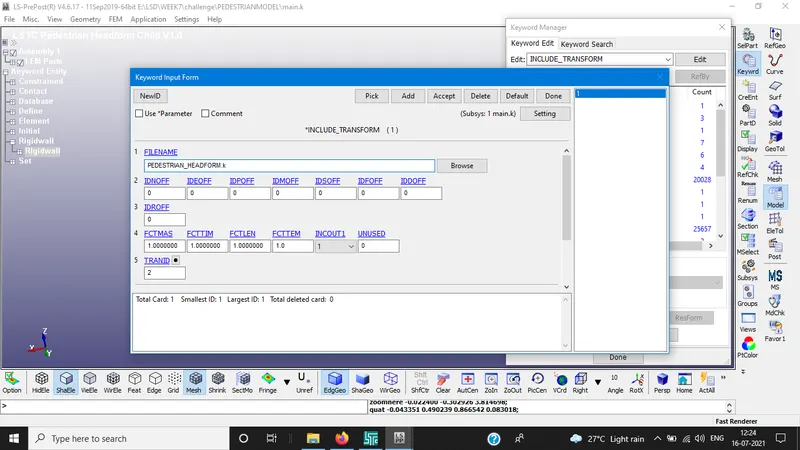
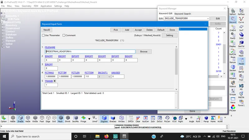
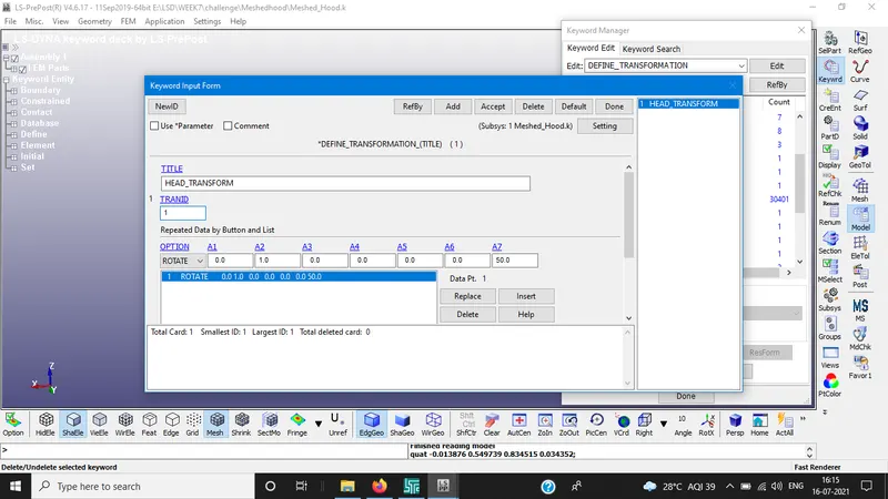
Since the transformation of the geometry is necessary to replicate the real impact situation. DEFINE_TRANSFORMATION is used to rotate the model around the Y-axis *INCLUDE_TRANSFORM card is necessary to complete the rotation procedure.
In this card, original gometry is called through filename and define transformation is carried out on that geometry. TRANS ID is set to 1 for the model. Both the input files should be in the same folder.
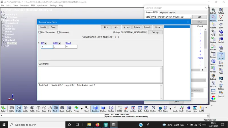
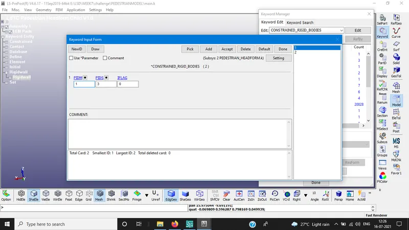
CONSTRAINED NODES:
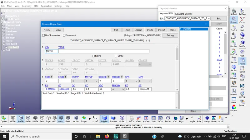
CONTACT CARD:
CONTROL TERMINATION:
DATABASE:
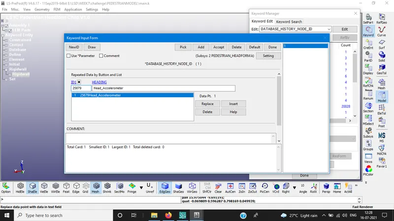
ASCII
GLSTAT, NODOUT, MATSUM and RWFORC are activated.
DEFINE CURVE:
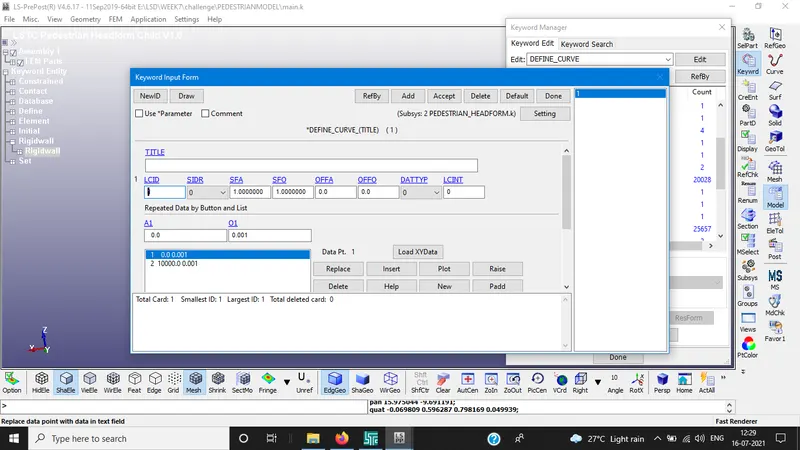
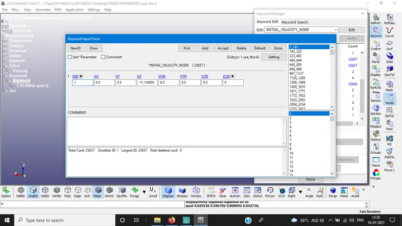
INITIAL VELOCITY:
Velocity applied at negative Z-axis with (11.11mm/ms).
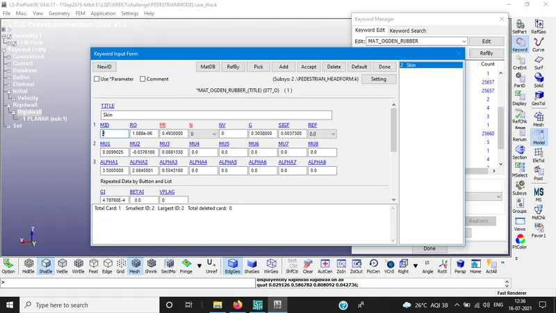
MATERIAL CARD:
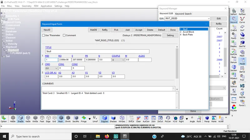
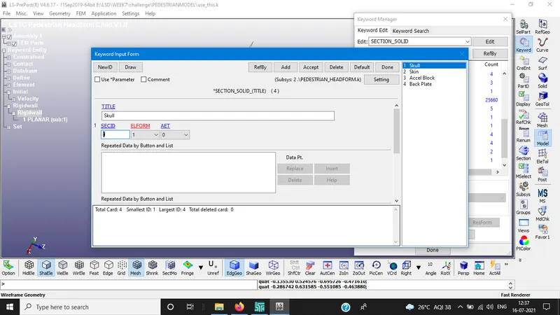
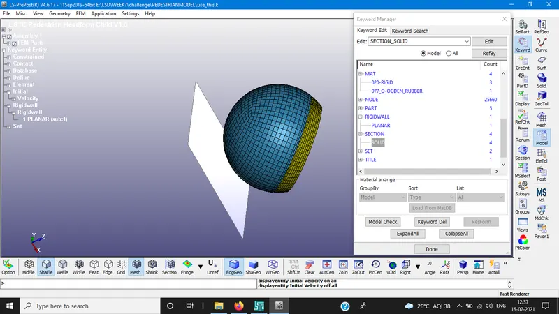
RIGIDWALL AND SECTION:
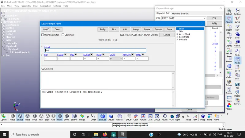
PART ID ASSIGNING:
RESULTS:
STRESS VALUE:
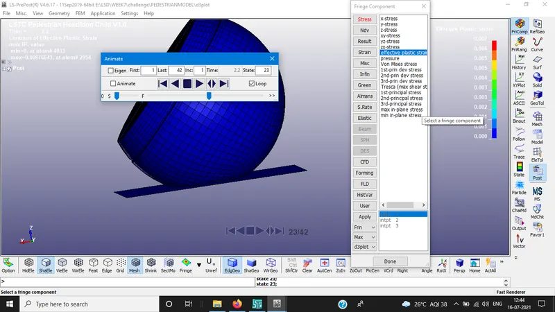
EFFECTIVE PLASTIC STRAIN:
HIC:
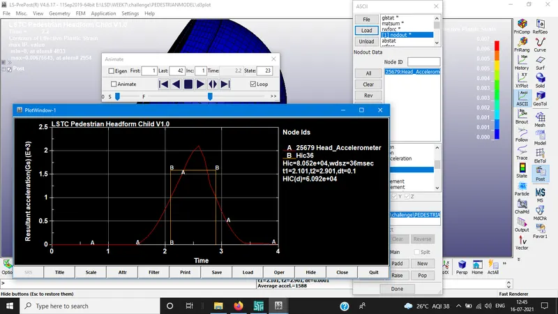
HIC-36 value for headfoam is measured from an accelerometer placed in geometry. From, the resultant accelaration increased then decreased after the impact.
HIC 8.052e+04
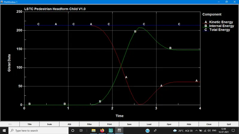
GLSTAT ENERGY GRAPH:
RWFORC: (Z-AXIS)
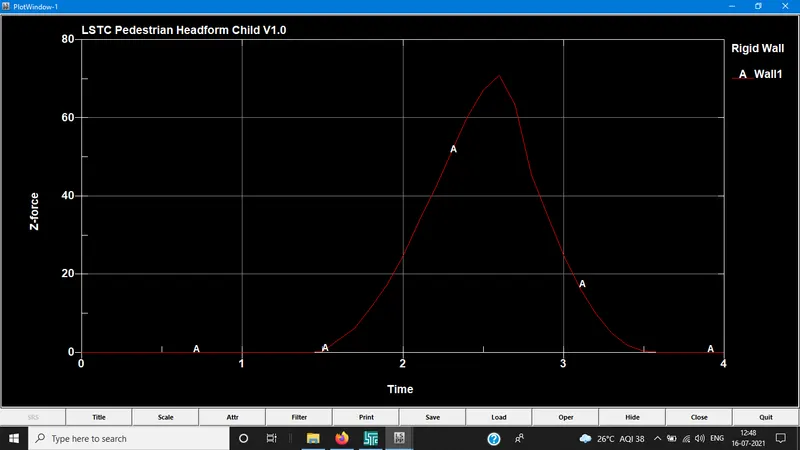
Energy plot for headfoam impact on rigid wall, the Kinetic energy decreases as internal energy increases at the impact since the head foam is modeled with hyper-elastic material there is gradual changes in energies during and after the impact. Compared to previous simple model some of the energy is absorbed in deformation caused.
CASE 3: CHILD HEAD FOAM AND HOOD COLLISION
The release angle of head is 50 degrees. The head foam velocity impact is at 11.11ms/ms(40Kmph).
Since the transformation of the geometry is necessary to replicate the real impact situation. DEFINE_TRANSFORMATION is used to rotate the model around the Y-axis *INCLUDE_TRANSFORM card is necessary to complete the rotation procedure.
In this card, original gometry is called through filename and define transformation is carried out on that geometry. TRANS ID is set to 1 for the model. Both the input files should be in the same folder.
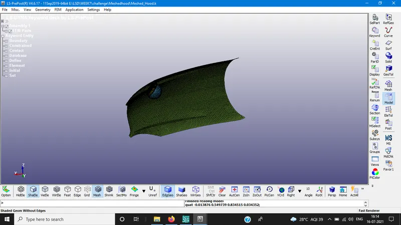
BOUNDARY CONDITIONS:
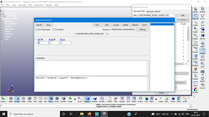
Select the edge elements of hood and create a node set . To the node set constrain the elements in all dof's i.e., creation of spc set.
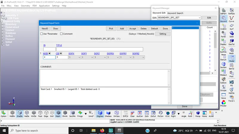
CONSTRAINED:
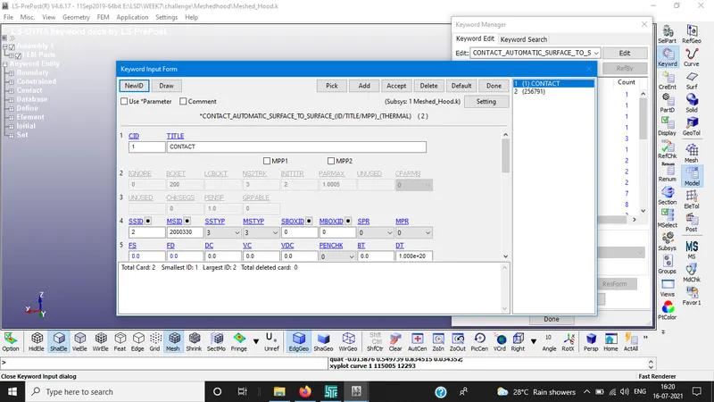
CONTACT:
Automatic surface to surface contact is assigned to the hood and head foam.
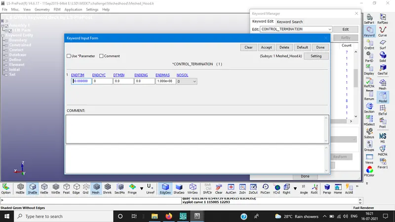
CONTROL TERMINATION
DATABASE CARDS:
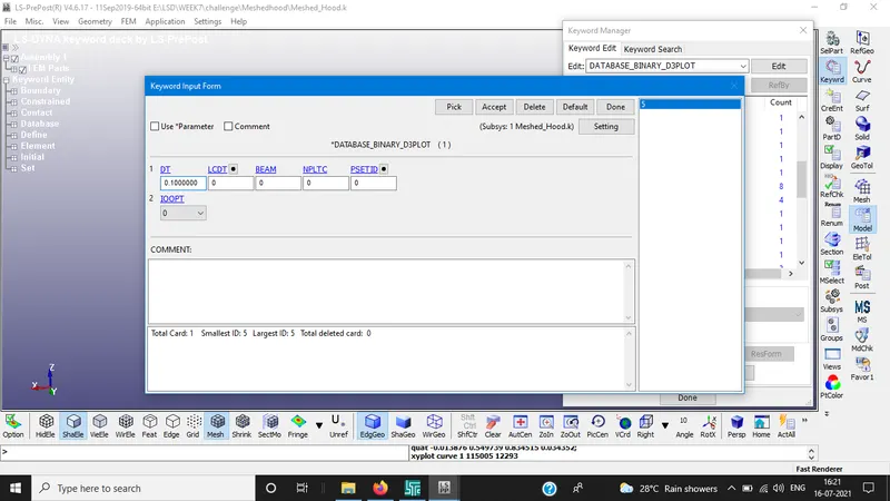
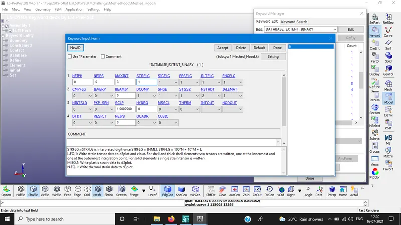
for the above STRFLG value is recorded as 1 because it saves the strain data to d3plot.
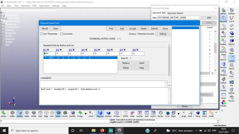
ASCII OUTPUTS
GLSTAT,MATSUM,NODOUT and RWFORC are activated.
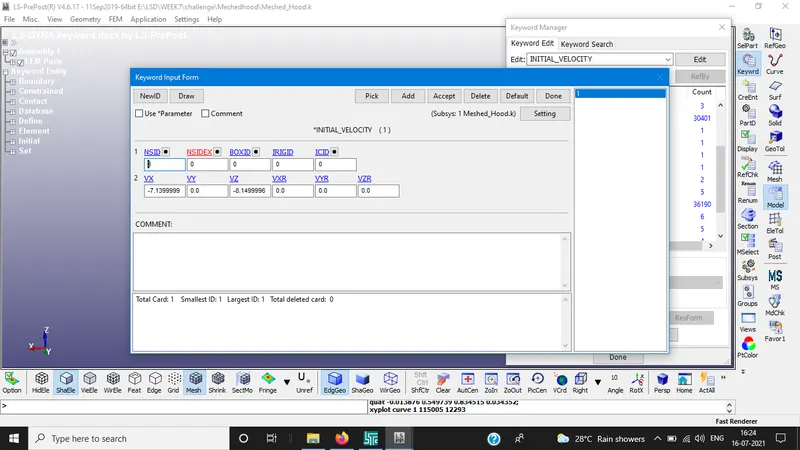
INITIAL VELOCITY:
Since the head foam is tilted at 50 degrees and the velocity value is given at negative X-axis and Z-axis. Though the values is 11.11mm/ms but the due to 50 degree angle right angle formula is applied so,
For Vx = COS(40) * 11.11 = 7.9
FOR Vz = SIN(40) * 11.11 = 8.1
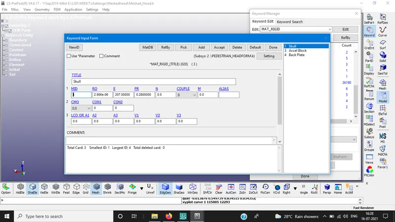
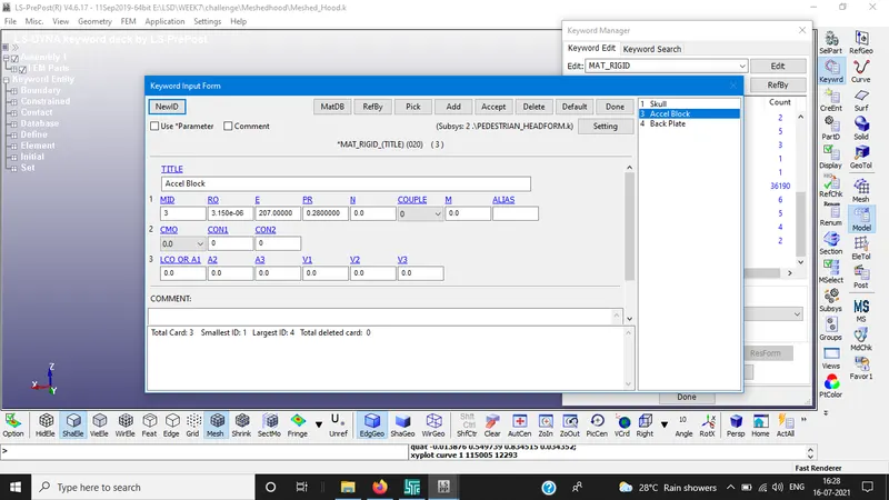
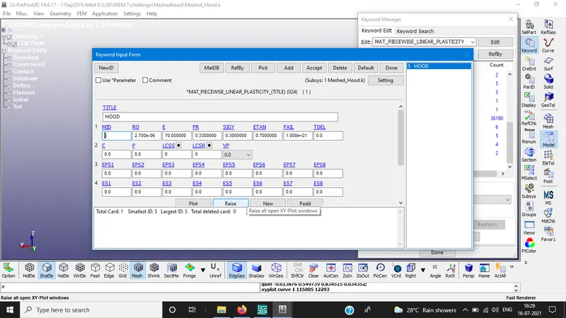
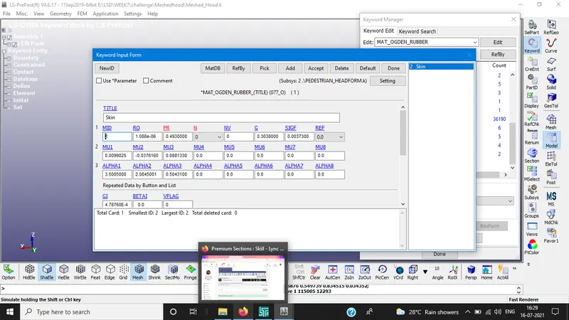
MATERIAL CARDS:
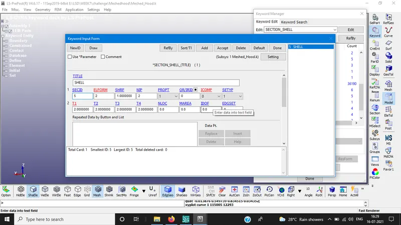
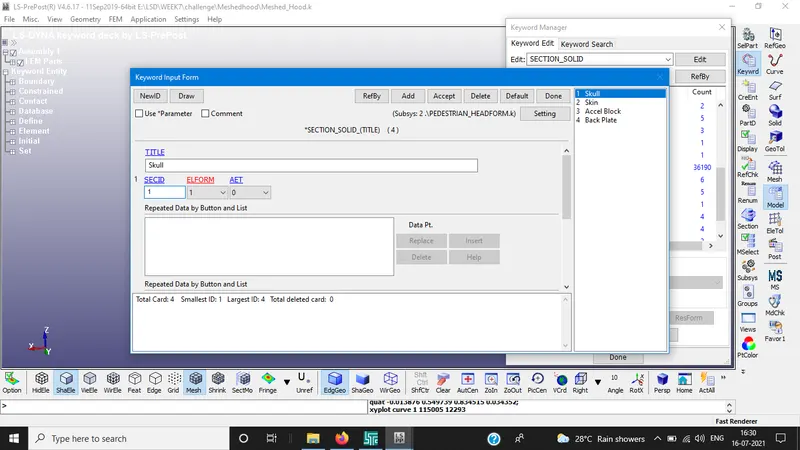
SECTION CARDS:
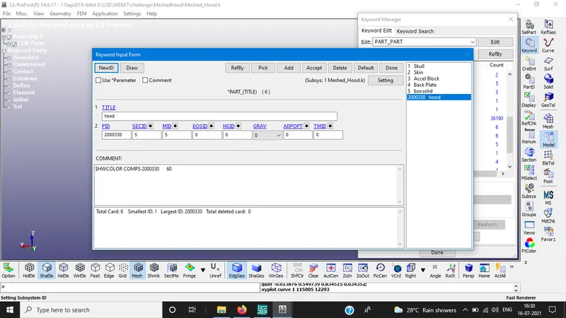
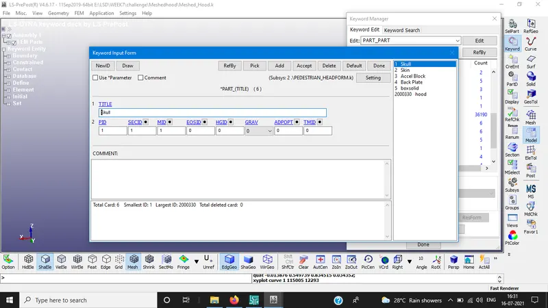
PART ID'S:
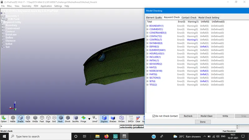
MODEL CHECK:
RESULTS:
STRESS VALUE: 30.3 Mpa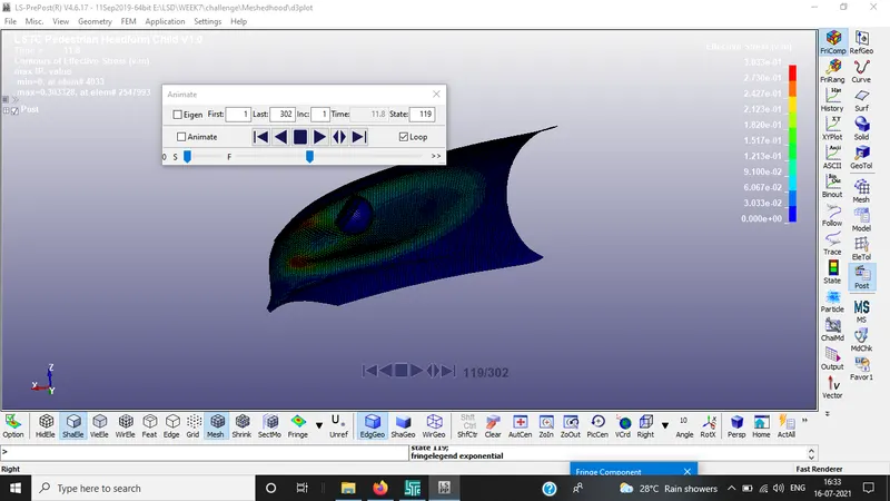
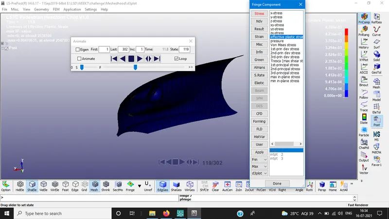
STRAIN RATE
HIC :
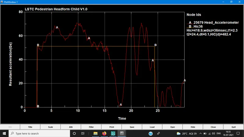
HIC: 418.9
GLSTAT ENERGY:
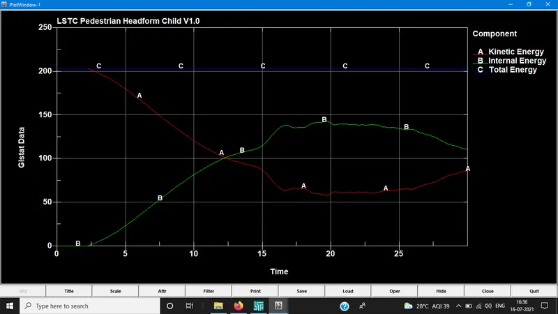
CONCLUSION:
CASE1 :
The simple head model was defined with MAT_Elastic material card which implies the material is pure elastic so, the max stress is only there in time of the impact there is no significant deformation in the simple head geometry.
CASE 2:
The standard model of the child head foam with exact material was applied, the rigid wall is undeformable so that stress is transferred to head and deforms the geometry of it severely HIC values are lower than case 1
CASE 3:
With standard head model but in this case it collisions with car bonnet to study the real time concept. Hood was defined with piece wise linear plasticity which is deformable so during impact the hood deforms significantly and reduce stress and strain on the head foam and thus reduces HIC value lower than case 2