Meshing on the suspension Assembly
PROJECT 2
MESHING ON THE SUSPENSION ASSEMBLY
AIM
For the given suspension assembly, check for the geometrical errors and mesh with the given element Quality criteria. After meshing the component the thickness has to be assigned for mid surfaces. Use tetra elements to model non-uniform thickness components. Also use appropriate connections to connect the component. At last perform Symmetry command to reflect the half finished model to the other side.
Quality Criteria for Surface Meshing of Tyre and Rim (Element type: Tria) :
|
S.No |
Quality Criteria |
Value |
|
1 |
Target/Average length |
6.5 |
|
2 |
Minimum Length |
5 |
|
3 |
Maximum Length |
10 |
|
4 |
Skewness |
45 |
Quality criteria for Surface Meshing of Non Uniform thickness components other than Tyre and Rim (Element type: Tria) :
|
S.No |
Quality Criteria |
Value |
|
1 |
Target length |
4 |
|
2 |
Minimum Length |
2 |
|
3 |
Maximum Length |
6 |
|
4 |
Skewness |
45 |
Quality Criteria for Volume meshing of all Non Uniform thickness components (Element type: Tetra Elements):
|
S.No |
Quality Criteria |
Value |
|
1 |
Tet-collapse |
0.2 |
Quality criteria for Mid surfacing of Uniform thickness part which has thickness less than 5 mm (Element type: Mixed elements) :
|
S.No |
Quality Criteria |
Value |
|
1 |
Target/Average length |
4 |
|
2 |
Minimum Length |
2 |
|
3 |
Maximum Length |
6 |
|
4 |
Aspect |
3 |
|
5 |
Warpage |
15 |
|
6 |
Skewness |
45 |
|
7 |
Jacobian |
0.7 |
|
8 |
Minimum Quad Angle |
45 |
|
9 |
Maximum Quad Angle |
135 |
|
10 |
Minimum Tria Angle |
30 |
|
11 |
Maximum Tria Angle |
120 |
WHAT IS SUSPENSION?
Car’s suspension system is a protective lattice of shock-absorbing components such as springs and dampers. Your car’s suspension helps ensure that your drive is safe and smooth by absorbing the energy from various road bumps and other kinetic impacts. Furthermore, it helps your tires stay in contact with the road by increasing tire friction.
Think of the suspension of your car as a kind of carriage on which the car’s main cabin sits. Your cabin is made more comfortable because it is sitting on the suspension, which is connected to the car’s wheels. The vehicle and its cabin are insulated against impacts that are common when driving, even on well-paved roads.
The main parts of a car’s suspension include:
- Springs, which help to control the height and load of the suspension and cabin.
- Shocks (also called dampers), which absorb and dampen various kinetic energy impulses that your tires transmit when they contact the road.
Your car’s suspension system also likely has an anti-sway bar. The anti-sway bar can help to shift the movement of your wheels relative to your steering wheel. It effectively stabilizes your car’s direction as it moves along the road.
Your car likely has a suspension system for both its front wheels and its back wheels. Suspension systems can be either independent or dependent:
- Independent suspension systems are used when your back or front wheels move independently of the front or rear axle, respectively.
- On the flip side, dependent suspension systems are used when wheel direction is bound by axle movement.
What Does a Suspension Do?
To fully understand what you’re suspension does, you have to grasp what would happen if your car didn’t have one.
When you drive on the road, your car’s tires naturally roll over various imperfections and bumps. Those bumps interact with your car’s wheels, applying force each time. The laws of physics dictate that every force exerted on an object has magnitude and direction.
When you encounter a bump on the road, it forces your wheel to move up and down at a perpendicular angle (vertically relative to the road’s surface). Of course, small bumps won’t transmit a lot of vertical kinetic energy to your car. But larger road bumps or surface imperfections can transfer quite a bit of energy.
It’s common sense; when your car’s wheels hit a bump, your car receives energy and jolts upward or downward.
If you didn’t have a suspension, all that energy would transmit into your car’s frame. That kind of energy transfer can make riding in a car uncomfortable at best. Furthermore, your car might hypothetically lose its grip on the road, causing the wheels to jump up, then slam back down on the road’s surface.
Your car’s suspension:
- absorbs the energy transferred through your car’s wheels
- helps your car cabin to ride atop the suspension relatively smoothly, even when riding on imperfect roads
The two core components mentioned above both play a vital role in this process. The shocks or dampers absorb the impulses, with kinetic energy traveling along the dampers instead of transmitting to your car’s cabin (to the same degree, at least).
Meanwhile, the springs attached to your suspension flex and expand to control the dissipation of that kinetic energy. They prevent your car’s suspension from bouncing up and down too much, as well.
Combined, both of these components keep your car’s ride feeling relatively level and even.
Why Is the Suspension So Important?
Each modern car is equipped with a suspension due to its benefits. For example:
- Suspension systems maximize the friction between your car's tires and the road. By maximizing friction, you can steer your vehicle with more stability and experience more comfortable handling. The more contact your tires have with the road, the safer and more securely you'll be able to drive.
- The suspension system of your car also provides added comfort. By limiting the kinetic energy transferred from road imperfections like bumps to your cabin, you’ll bounce up and down far less, and your passengers will also enjoy a smoother ride.
- Furthermore, suspension systems can help to increase the lifespan and durability of your car. Your vehicle’s components will be taxed much less over time by limiting how much energy is transferred from bumps and potholes in the road. Therefore, your car’s other components will last longer.
Ultimately, your car’s suspension system is just one of the many crucial components required to ensure a safe ride whenever you hop in your vehicle. Without suspensions, vehicles would be bumpy at best and, at worse, hazardous.
Make sure that you keep your suspension system in good condition by periodically taking your car in for an inspection with a certified mechanic. We strongly suggest taking your vehicle in for repairs if your ride ever becomes too bumpy or you suspect that your suspension is possibly wearing down.
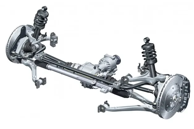
IMAGE OF SUSPENSION IN AUTOMOBILE
How Does Car Suspension provide Control
Before we can get into how suspensions provide control and types of suspension we need to study wheel alignment and how it helps the types of suspension.
Wheel Alignment
Its what the names say, its the position of wheels in relation to something. Something, in this case, is the steering axis. There are types of wheel alignments that help and hamper suspensions and we will learn them at length below.
Some terms that will be used in the upcoming blog and might need a bit of an explanation as to what they mean
- Steering Axis– Its the axis at which the wheel will rotate on.
- Scrub Radius– The distance a tire has to rotate to make a turn. The smaller the radius the fated the turning point.
Before we start wheel alignments and its types we need to study about Steering axis inclination and how it helps alignments of the wheel.
Steering Axis Inclination
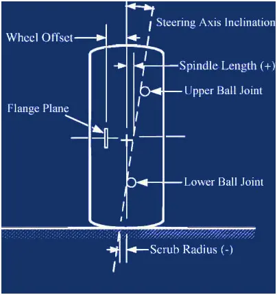
Steering axis Inclination | Car suspension explained
The Axis on which a wheel rotates is steering axis. Pretty straight forward on that. What about the inclination part though. You can see that none of the steering wheels is ever straight. This is to have an inclination. This along with a positive camber helps reduce the scrub radius which in turn reduces wear and tear of tires. This also reduces the effort on the wheels making the car do a little bit of a jump. What is a jump of the car and how does it help us?
When a tire is rotated on an incline it goes both in the direction of rotation and it also tends to go downwards. This causes the car to lift up slightly as the ground cant be pushed down any further. This happens only during a turn. This is the reason when you sometimes take your hands off your steering wheel after a turn your car goes back to its normal state which is driving straight forward. This allows wheels to instantly go back to driving straight giving the car a fast recovery time. You might now this phenomenon and it’s possible either you use it or someone you know does. Its when you take a large turn and when the car is accelerated the steering wheel automatically goes back into its normal state.
Steering Axis inclination is also a necessary component in almost all of the wheel alignments and is necessary to understand how rest of the wheel alignments work.
Camber
The angle made by the tire and the vertical axis of the car is called camber. In layman terms, if you look at the car from the front it’s the angle which you can see the tires coming outwards or going inwards. But you’ve never seen them go inwards or outwards right? Its because those angles are really small and are almost not visible. They still play a major role in the stability of the car and helping suspension. There are two types of camber, positive and negative. Positive is when the top of the wire is outwards making it so the inner portion is towards the car while the top is facing outwards. Negative camber means the top of the tire is inwards towards the car while the bottom is away from the car facing outwards. What is the use for positive and negative camber though?
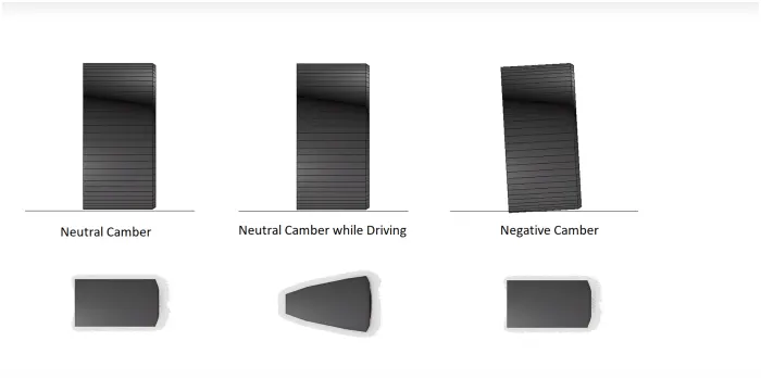
Negative and Neutral Camber
When you have a tire with no camber angle, on a straight line its contact shape will be a rectangle. Taking a turn, however, will make it so that the contact shape is still a polygon but has a smaller surface contact. The more spread across the outside of the wheel causes it to work more than the interior thus making the car have less grip while talking turns. To counter this camber is used.
Negative camber will make the turning patch a rectangle again but at the cost of the straight-line patch which will now become the polygon. This makes negative camber more useful in race cars as driving in a straight line is not as necessary as driving fast around corners where the races are usually decided.
Positive camber, on the other hand, is used in normal vehicles that don’t need to take sharp turns at high speed and are provided to give a comfortable driving experience.
Caster
Angle made by the steering axis with the vertical axis when looking at a car from sideways. Let’s expand on this a bit further. The vertical axis is a straight line that goes through the middle of the tire while the steering axis is inclined as we have read above thus making an angle with the vertical angle. Looking at the car from the side and when the steering axis is ‘behind’ the vertical axis its called a positive caster. We will not be discussing negative caster as there is no need for a negative caster angle. Do note that these angles are really small and most figures shown are an exaggeration to help you understand how these angles work.
When a turn is taken with a wheel having positive caster the tire will want to go back to its normal position which is prevented by the driver through applying force on the steering wheel. The moment steering wheel is left the car goes back to driving straight. It is really difficult to drive a car without a caster angle at high speeds as you’ll constantly need to move the steering wheel to counter the car tires moving into positions that you do not want because they are trying to go back to the centre position because of a steering axis inclination.
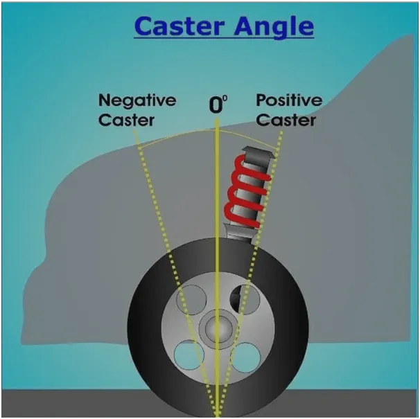
The caster angle also makes it so your tire always goes in the direction of the car. In short, when you are taking a turn instead of sliding sideways the tire will face the direction of the car. You can watch this in a shopping cart’s wheels or an office chair.
All this talk about the car going back to driving straight doesn’t seem something fancy and can be done normally by the driver. We will explain the point of having caster, camber and toe.
Toe-in and Toe-Out
For this wheel alignment to know the differences between the two of them you have to look at the car from above. If the front tires are further apart from the rear tires its called a toe out. Having the front wheels more inwards compared to the rear wheels makes it toe-in.
Toe-in is used in rear-wheel-drive and helps to keep the tires straight when a car is taking a corner. Toe-out being the opposite is used in front-wheel-drive to achieve the same result. Their working, however, is completely different. Toe-in uses the steering axis inclination. When the car is taking a corner it tends to roll, during this roll a toe-in will want to guy back to its original position due to steering axis inclination making it want to go back to its normal position (we discussed this earlier). This makes it so when a car is taking a turn the tires go along the direction of the corner instead of skidding across it reducing tire wear and giving suspension less work.
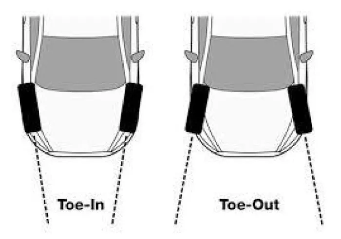
Toe-in and toe-out
Toe-out is used in front-wheel drives and is really necessary for taking turns and keeping the car driving straight. Under normal conditions due to steering axis inclination, the tires want to go inwards. So if the tires were at a neutral position meaning no toe-out it would result in an automatic toe-in which is not a good thing for a front-wheel drive. Why? Here’s why. Its because the front-wheel drive has a little understeer when taking a corner. If the car goes toe-in it will further add an understeering making it really difficult to take turns. A toe-out, however, counters both of these things by preventing the tires to go into toe in when driving straight and giving extra oversteer to counter the understeer of FWD.
As we are equipped with the knowledge of wheel alignment we can now tackle types of suspension. If you skipped this part and are now reading it again because of one the suspension types heavy focus on it, don’t worry we won’t judge.
Types Of Car Suspension
We will be discussing three types of suspension, a double-wishbone, MacPherson strut and solid axle suspension. All these suspensions have different advantages and are good in their respective uses.
Double Wishbone / Double-A Arm Suspension.
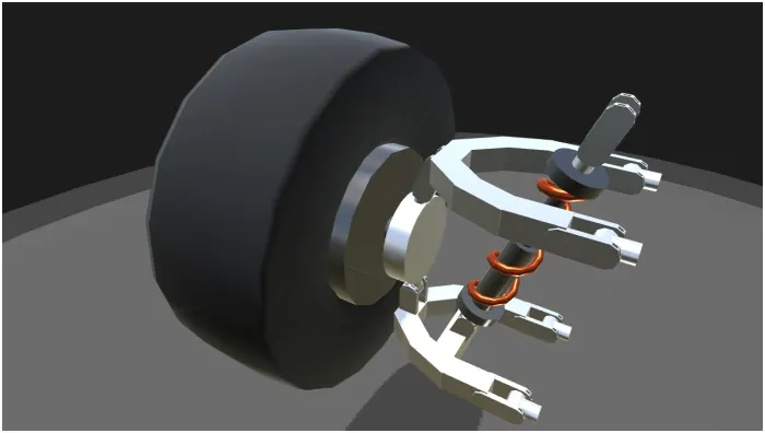
Double Wishbone Car Suspension
The image must have cleared any doubts about the name. It has two control arms in the shape of the letter A aptly named Double-A arm. For why its called wishbone because its the shape of a bone found in birds named wishbone hence the name. Let’s get into everything about a double-wishbone suspension.
Construction
The end of the A or the wishbone is connected to the frame while the top part of A is connected to the wheel. The end of A or the two ends are called control arms. They are uneven in size (it will be explained later why it is so). The struts go through the middle of the control arms. The material used for its construction is chromium-molybdenum steel. Lets clear the air over why it uses an uneven control rod before we get into the working of the double-wishbone suspension.
Why Does It Have Uneven Control Rods
One of the control arms is shorter in size, the top one to prevent tire wear. If both the control rods will be equal there will be positive camber on the side of the opposite side of the turn. We will take an example to help you understand this a bit better without one it barely makes any sense.
Take a car which is going to turn left, centrifugal force states that the car body roll towards the right a bit. When we take turns this happens to our cars too but they don’t overturn due to physics. They do cause some problems for our tires though. In the case of a left turn, the right front tires will face more tear than the left one. We know its a bit confusing to explain it with words but well try to elaborate nonetheless. When you have positive camber on the right-side tire, the right tire will be on the ground while the left tire will be floating a little bit. This will put a lot of work on the right tire causing more tear to it.
To prevent this, engineers used the knowledge of camber and changed the size of the control rods. Making the control rods shorter will change the camber angle. This will cause the right tire to get a negative camber and left tire to get a positive one causing the left tire to make contact with the surface and right tire getting a neutral camber overall when the car turns thus causing both tires to have contact with the ground.
Advantages Of A Double Wishbone
- The advantage of a double-wishbone suspension system is that the sharper the turn of the car the more control it will provide. This ensures control in any corner scenario. Not all suspension can do this task thus making double-wishbone a really strong suspension system in faster cars.
- Due to the freedom of movement of the control arms, a car with the double-wishbone suspension system can go through large holes or bumps in the road and it will still cushion the blow. As the arms can move a lot they will negate the forces. other suspension systems do not have this big of a deflection capability. It is also a good pick for offroading vehicles.
- Double wishbone is versatile in the way that you position the strut anywhere on it. There is no hard rule about it being in the middle of the wishbone or on top of it. It all depends on the vehicle if it has enough space or not.
Disadvantages Of A Double Wishbone
- Because the world is no utopia, this very thing has a good and a bad of it. The bad of a double-wishbone is that it is costly. Compared to other alternatives, a double-wishbone is costly and it is worth the money. More affordable cars thus, for this reason, don’t use this to keep the car budget-friendly.
- Double wishbone has a lot of parts involved. The more parts an object has the more possibility of it failing as even a small part that doesn’t work will cause an issue. It doesn’t mean wishbone keeps on failing every single chance it gets. Its just probability that it might fail more than others. More parts also mean more work required to get any fault corrected.
- Double wishbone is still one of the best suspension systems out there. Let’s discuss the rest of the suspension system and see why they are strong in their respective areas.
MacPherson Struts
Made by the man named Earle S. MacPherson in the year 1945 MacPherson struts still find use in cars that want a reliable yet cheap suspension system lets learn about this suspension system from its construction to its advantage below.
Construction
The MacPherson strut uses a single wishbone control arm which connects the car to the wheel hub. The wheel hub in this suspension is the most important pivot point as every part of the MacPherson strut connects to it. A shock absorber/damper with a spring or in other words a strut is attached from one end to a wheel hub and from the other end to the car body. This is what makes it unique in its own way as it is the only suspension system that has the strut directly connect to the body. In double-wishbone, it was connected to the control arms in a multitude of ways but not directly to the car body. The steering link connects to the hub at the same point where the strut connects making allowing the MacPherson strut to be considered as a steering axis. There is a huge gap left in the middle of the wheel hub making it really good for FWD.
Use In A Front Wheel Drive
As we discussed in the construction part, there is space left in the middle of the wheel hub which can be used in case of an FWD. this space is used to fix the driveshaft in making this suspension really good for FWD. something like a double-wishbone will not be able to accommodate the driveshaft correctly and would need adjustments.
Advantages Of A MacPherson Strut
- MacPherson strut has it’s good and bad. One of the goods we just discussed above that being the ability to have a driveshaft in front-wheel without any changes necessary.
- MacPherson strut is one of the cheapest suspension available. On top of costing less, it is also lighter than other options making it a bit more fuel-efficient even though a few kilos mean nothing in the shorter but every gram helps.
- Due to being cheap, most entry-level cars use it which allows them to stay in budget and stay affordable to the masses. And being lighter structure changes are not necessary to accommodate the suspension allowing for decently strong structure thus making the cheaper cars stay in the budget again.
- Being narrower than a Double wishbone system, MacPherson strut can be placed in a smaller place allowing the car to use the rest of the space for something else. It also uses fewer parts than a double-wishbone making it less likely to get a fault while working.
Disadvantages Of A MacPherson Strut
- The biggest disadvantage of a MacPherson strut is the lack of camber gain. In the case of a double-wishbone arm, the more the car rolled the more camber gain was present. This is not the case in MacPherson strut. What this means that it will have less control on sharp turns at high speed as compared to a double-wishbone suspension system. This makes it unusable on high trim cars that flex on the ability to have really high speeds and good cornering.
- The reason for MacPherson strut not having a camber gain is because of the strut being mounted to the body. This restricts the movement of the strut and allows for no camber gain.
- MacPherson strut is mounted on the body and thus needs a unibody construction. A body on frame design will not be rigid enough to withstand the MacPherson strut and thus will not work. It is not that big of an issue anymore as most cars use unibody anyways so the use of MacPherson strut doesn’t hamper any designs and plans. This, however, means that the force and needs to be taken by the unibody making it a bit less effective than a double-wishbone as due to its good freedom of movement it can overcome most deflections, unlike MacPherson struts which are limited and cant handle large bumps and potholes in the road.
This covers the MacPherson strut and now we are left with one suspension system, Solid Axle Suspensions.
Solid Axle Car Suspension
Mainly used for trucks and other heavy-duty vehicles, solid-axle suspensions are placed on the back of a vehicle. The entire body weight is balanced on the suspension system. These are heavy-duty and can withstand a lot of weight. There three multiple ways to use a solid axle suspension which will be discussed now.
Types Of Solid Axle Suspensions
The types are defined by what components they use. We will discuss three types of solid-axle suspension and look into their construction, advantages and disadvantages. It is to be noted that these types are used alongside the solid axle suspension and are not a suspension on their own.
Leaf Springs
Most commonly seen in older trucks and buses, leaf springs are one of the three systems that are attached to a solid axle hence named a solid-axle suspension. They are quite cheap to make and are decent at best.
Construction
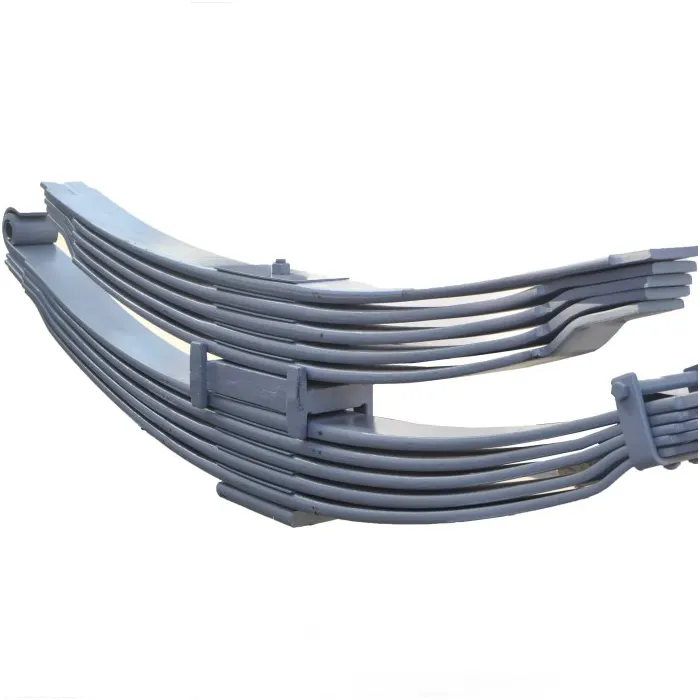
Leaf Springs | Car Suspension Explained
The leaf springs are made up with a number of plates which start long and keeps on getting shorter. Rebound clips are used to clamp these plates together. The longest leaf or plate is called the master leaf while the remaining are called graduated leaves. This entire spring is then attached to a solid axle using a central clamp and U-bolts. Leaf springs are attached parallel to the ground on rear tires to get the maximum possible work done. Materials used for the construction are usually 50cr1, 50 c11 V23 and 55 Si2 Mn90. if you have never heard those names earlier it’s fine we haven’t either. These are names of the alloys and are common knowledge to manufacturers.
Advantages
- Leaf Springs are cheap to manufacture and to use making them cost-efficient. There are also not that complex and thus don’t require a lot of manpower to create.
- These are also really durable and strong and can withstand a lot of punishment and last really long.
Disadvantage
- The work that leaf springs are supposed to do is to negate any and all horizontal movement. It, however, is not that good at it. It’s not like leaf spring suspensions are bad per se but there are other options that are better and better. Also, note that leaf springs cannot be used with another suspension link that we will discuss below making them a lone wolf.
- Leaf springs have a lot of unsprung weight with them which doesn’t really make them ideal for being used for suspension either.
Now we move to the second type of Solid axle suspension the trailing control arm.
Trailing Control Arm
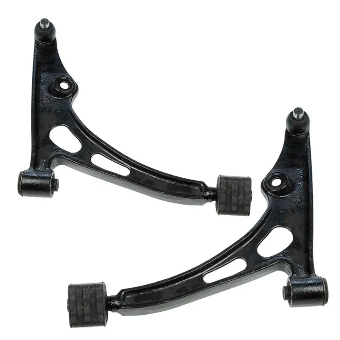
Trailing control arms
The biggest issue with a solid axle is that there is nothing to stop side to side or forward and backward movement. Leaf springs are used to stop the movements but only the top and bottom ones and it is not good at it either. In comes trailing control arm which can prevent forward motion and side to side motions.
Construction
There is not much in terms of construction for it as its just two additional control arms. Trailing control arms are attached to the chassis and the solid axle. They are made up of wall cold rolled steel tubing offering more strength. These arms can be adjusted according to requirements and don’t even need to be taken off the car to get an adjustment done.
Advantages
- Trailing control arms negate any and all the motion that the solid axle experiences. This includes side to side movement and forward movement by locking down the axle using the control rods.
- Similar to leaf springs trailing control arms are also really strong and durable.
- It can be paired with a Panhard Rod and thus negating one of its disadvantages.
Disadvantages
- It cannot stop lateral movement at all and may cause issues with it. Any vehicle that will go through a more vertical movement cannot use this system.
- Other disadvantages carried over from leaf are a lot of unsprung weight making it unpredictable.
- If a vehicle needs to prevent lateral motion they employ the use of the next system. The Panhard rod
Panhard Rod
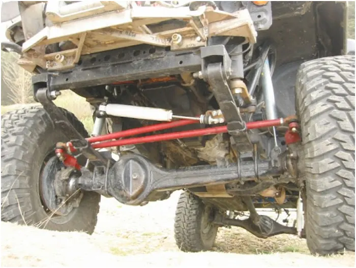
Panhard Rod and Solid Axle | Car Suspension Explained
The third type of system the Panhard Rod suspension links main work is to stop lateral (side to side) motion. It was invented in the early twenties by the Panhard automobile company of France and still sees work to this day.
Construction
Panhard Rod is simple in terms of how it is constructed. It has a rigid bar running sideways and on the same plan as the axle. The ends are connected to the chassis and solid axle from one end each. The ends are attached on pivots and this causes it to move upwards and downwards.
Advantages
- Panhard rods being really simplistic in design doesn’t require a lot of money to build and doesn’t need spending a good amount of cash to fix them.
- The fact that they can be paired with a trailing control arm suspension link allows them to negate one of their disadvantages.
Disadvantage
- Panhard rods cannot be used on smaller vehicles as the smaller the radius the more sideways movement will go through it.
- When using Panhard rods the axle needs to move in an arc along with the body else the
- Panhard rods will not work and negate all of its advantages.
Now that all the types of suspensions are done and we now know how they each help in their own ways to help keep contact with the ground we know need to know how suspensions do the final thing that they are supposed to do, Control of the car.
How Does Suspension Provide Control?
The control is just a bonus thing suspensions do because of keeping tire contact on the ground at all times. This is because keeping the tire on the ground at all times actually amounts to having control on the car anyways.
As we studied above every car suspension provide comfort and makes sure that all the tire are equally on the ground and not being uneven causing tire wear and less contact on the ground. Having this contact on the ground means more surface area which in turns more control over the car and its movement as bigger the surface area of something they easier it is for it to keep balance. This can be explained using the centre of mass.
Physics states that an object always has all of its mass on a point and not evenly distributed like we usually think it is. Sounds absolute lies right? You can try this with a small 15cm scale or a normal pencil. Try to balance them on your finger and you will notice a point where you can balance them without it falling. For a 15cm scale, it is around the 7cm mark.
What it means that the bigger the contact patch the easier it will be to balance the car. And the bigger patch is provided by the various suspension systems
As we have discussed how a suspension works and other related topics. Now, considering the given model which is front suspension with steering wheel rod has to be meshed according to the given parameters and give proper connections.
RIM
Since there are multiple parts we’ll go component by component.
For the Rim check the geometrical errors to before meshing .
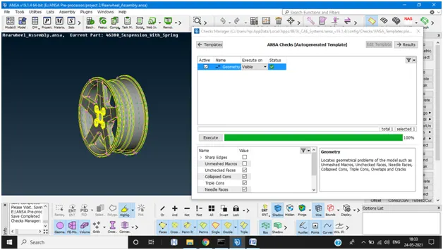
As we can see that RIM has no geometrical errors
Since the assembly is about the tria and tetrahedral meshing there is no of extracting the mid surface expect for the surface which are less than 5mm thickness.
Now, perform the tria meshing to all the surfaces. Before meshing the set the mesh quality as trias and mention element lengths.
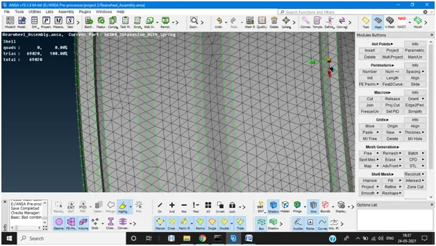
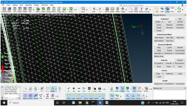
We acquired possible mesh flow given by ANSA. Now convert the shell mesh to solid mesh by Volume option. For the volume mesh check for the Tet collapse in our scenario it should be 0.2
- For the Volume mesh first define the shell elements in to volumes to go through Volume mesh>Define>manual>select the volumes>click ok.
- Now set separate PID for the solid mesh and mesh with the Tetra Rapid elements
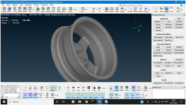
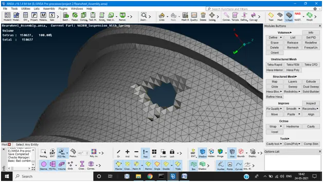
Above images are solid meshed surfaces
TYRE
Similar procedure is repeated for the tyre as first check the geometrical errors then do the shell meshing.
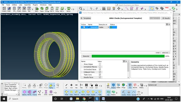
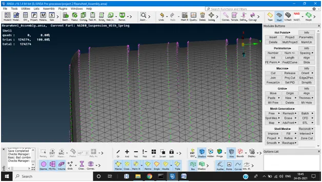
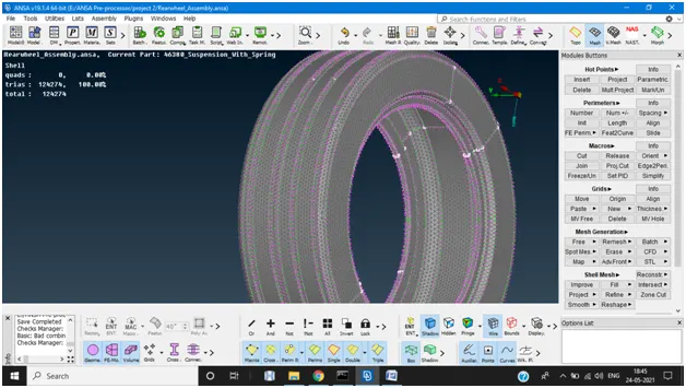
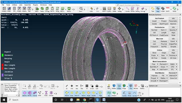
Above images represent the shell mesh of tyre
Now define it as volumes and mesh the volumes into tetrahedral elements.
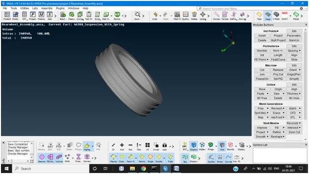
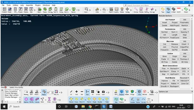
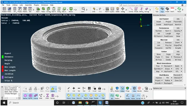
Creating a PBAR elements for the suspension spring
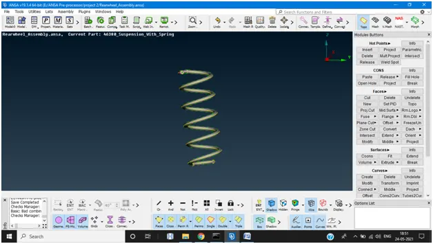
Now Using middle option in curves create curve for the spring
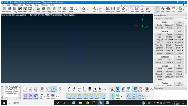
- Create a COG point for the curve to define the orientation (Topo>points>ON COG)
- Now to go to Nastran deck Elements > CBAR>Change the selection to curve box>select the curve and give the middle mouse click> select the orientation node> specify element as 3mm
- After that define a PID by creating new.
- Define area by giving radius of spring(give as radius 5)
- After that, assign the cross sectional radius of the element it will calculate and create the 1D elements
- For the representation 1D bar elements check the box of 1D detailed representation with solid in quality parameters.
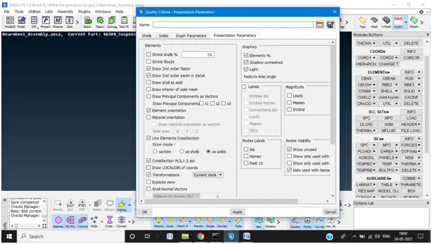
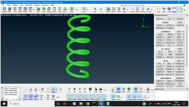
Above Image represents 1D bar elements
As mentioned that surfaces which are less than 5mm thickness should be meshed with mixed elements and assign thickness to the elements. Below are surfaces that are part of the suspension which has 3mm thickness.
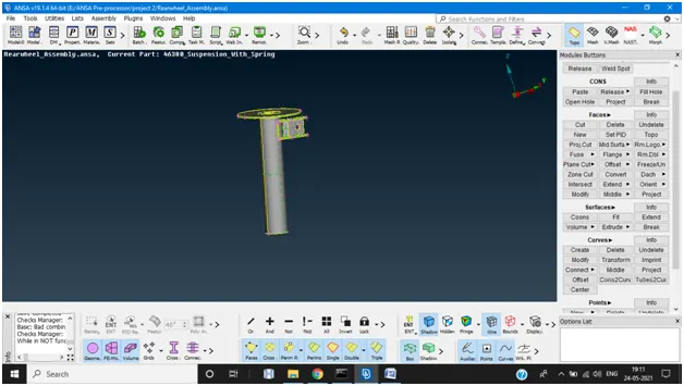
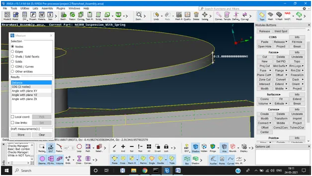
- For the above the surfaces extract the mid surface by offset option.
- TOPO>offset>select the one side of surface> mention the value> click ok
- Repeat the same process for the whole area
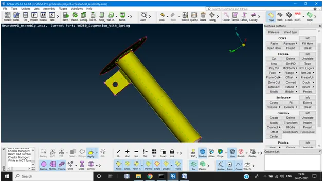
Above image is the extracted mid surface
- Now shell meshing should be performed on the surfaces with given quality criteria
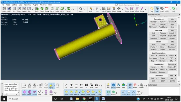
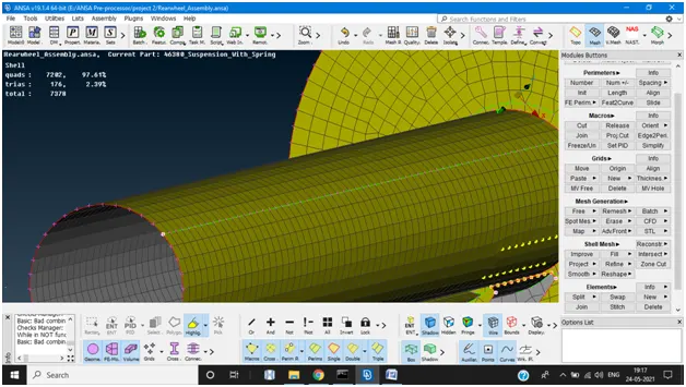
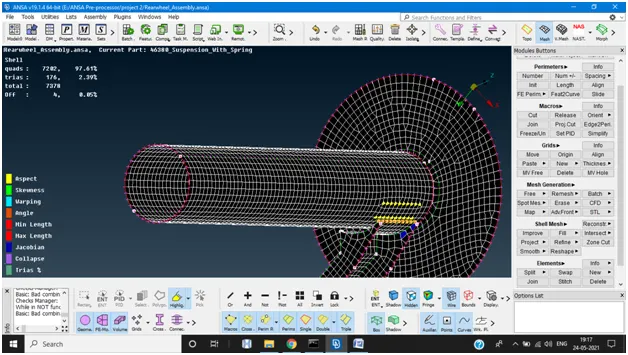
Above images represent shell meshing
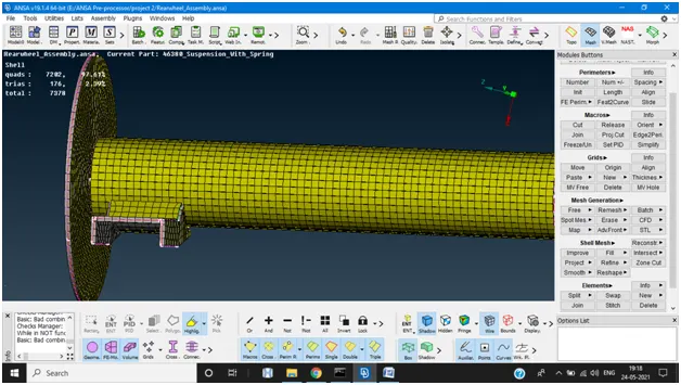
Above image represents that thickness is assigned to it
NOTE: For the component surface creating separate PID’s is prominent in model.
SUSPENSION ASSEMBLY (Tria elements)
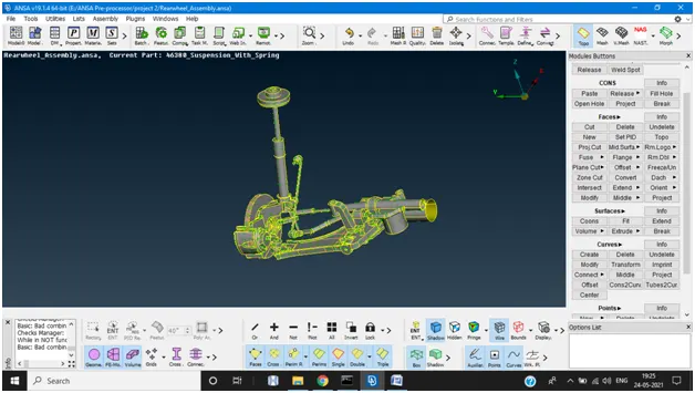
Above image represent rest of the assembly
- Since there are multiple parts create a separate PID for the meshing purpose
- For that use !not to create PID.
- After creating different PID’s perform tria mesh on each part as per given quality parameters
- After the completion of shell meshing on all parts check for the failed elements if any try to eliminate them by using split , swap and reconstruction of the elements.
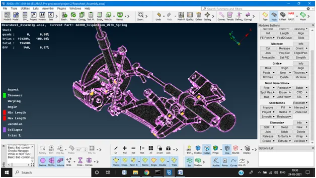
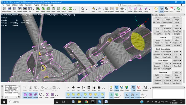
Above images represents shell meshing and assembled of all parts
In the same way as we did for the tyre and rim convert the shell elements into the tetra elements for all the parts
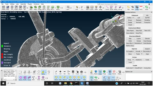
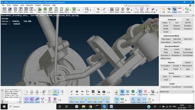
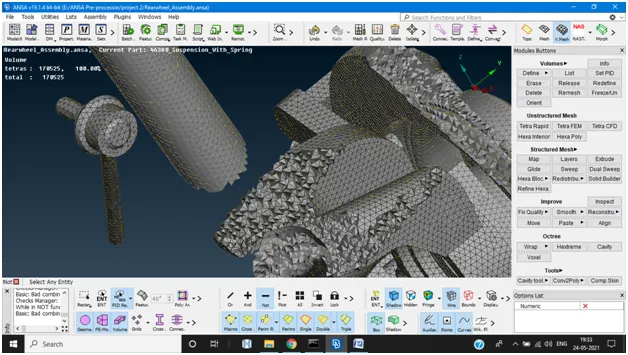
- Above images represent the solid meshing with no failure elements.
Now that we have completed whole meshing process giving appropriate connections to the model is most important.
Connections
For the whole suspension assembly I’ve learnt two types of connections are needed
- Bolt
- Seam weld
Bolt
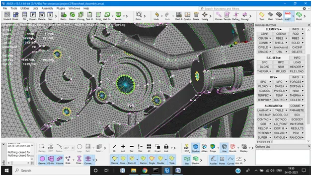
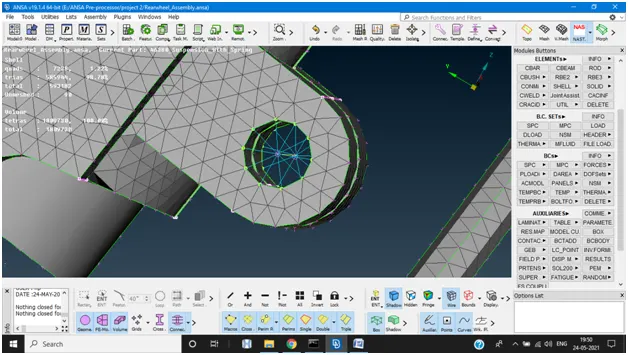
- As we have meshed most of the surfaces with tria elements cluster RBE2 elements connectors are used instead of the connection manager
- First we have create a midpoint by POINTS>on COG>select the loop > click ok
- Create the 3D points wherever it is necessary
- Now convert 3D points to bolts.
- Now go to nastran>RBE2>many elements>select the elements>click the middle mouse for 3times.
- After creating cluster RBE2 select the 2-node to connect the two cluster rbe2 elements which represent as bolt connections
Below are some images which represents bolt connections
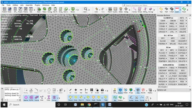
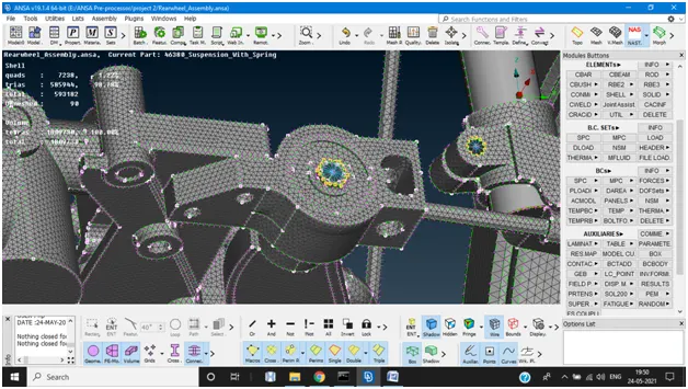
SEAM WELD
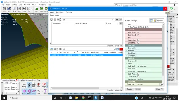
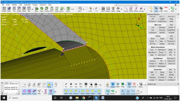
- Since the seam connection is performed on the 2d shell meshing connection manager is used to create the seam line
- First create a curve by using Fea2curve option in mesh deck
- Now convert the curve to seam line
- Click on the connection manager select seam line and click ok
- Now assign PID for the p1 and p2. To assign right click to modify> press F1 > click the part and enter
- Since the elements are parallel select the overlap shell
- Give search distance which should be the target element length
- Assign weld ID (shift+?) create new Id and enter
- Click on the Apply and realise to create a seam weld connection
Below is the image of seam weld
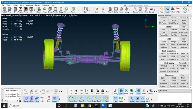
After the completion of connections mirror the whole assembly along with the connections and meshed surface using transform option.
Transform> select the total entities> symmetry (3 points mirror plane)>select 3 points >click ok and finish.
Below is the image of a whole assembly mirrored on other side of the plane
LEARNING OUTCOMES AND CONCLUSION
For the given assembly I’ve learnt how to perform the 3D meshing for the complex parts. This gave me a immense knowledge about the tool and its applications. And also, connections on where to apply them depending upon the model and its requirements.
NOTE
Hello,
Sorry for the inconvenience
Due to the large size of file website unable to upload. I am pasting the drive link please look into it.
Regards