Week-7 Head Impact
Aim:- To perform the head impact simulation and calculate the head impact criterion (HIC) value for the following cases.
Objective:- To perform the head impact analysis and calculate the HIC value for the following cases.
- simple head model and rigid wall
- child head foam and rigid wall
- child head foam and hood
Head Impact:
- About 14% of all road fatality in Europe are pedestrians, with children and the elderly being at the greatest risk. Pedestrian comprises one of the main categories of vulnerable road user which also include cyclist and motorcyclists.
- Most Pedestrian accidents occur within city areas where the speed are moderate. The head, the lower body and the legs are the most frequent injured body regions. To estimate the potential risk of Head injury in the event of Vehicle striking an adult or a child, a series of impact test is carried out at 40kmph using an adult r child Head form impactor. Impact sites are then assessed and the protection offered is rated as good, adequate, weak, marginal and poor.
- The procedure promotes energy absorbing structures, deformation clearance and deployable protection system such as popup bonnets and external airbags.
- Studies shows that the major source of child and adult pedestrian HEAD injuries is the top surface of the Bonnet of the striking vehicle. The Bonnet would be impacted with a head-form at 35 to 40kmph. The Bonnet would be divided into a “Child Head-from Test area and an “Adult Head-Form test area”. The child Head-Form test area is the area of the Bonnet that is likely to be impacted by the Head of a midsize adult male pedestrian is likely to impact. An adult head-form test area corresponds to the area of Bonnet that Head of a mid-size adult male pedestrian is likely to impact. An adult head-form is used to test the Bonnet I the latter area.
Child Head Impact:
- Car-pedestrian accidents accounts for a considerable number of automobile accident in industrialized countries. Head injury continue to be more concern with Automobile impacts, because Head is the most seriously sensitive part and injured in many collisions including in pedestrian vehicle collision. To reduce the severity of such injuries international safety committee have proposed system test in which head-form impactor are impacted upon the car hood.
Pedestrian Protection Test procedure as per AIS 100
- Currently in India, Automotive Indian Standard (AIS) 100, Amendment 1 is used to evaluate the performance of vehicle against pedestrian safety. This standard has been harmonized from the international evaluation Standard Global Technical Regulation No. 9 (GTR9), whose purpose is to bring about an improvement in the construction of the front of the vehicles and in particular those area which have been most frequently identified as causing injury when in collision with a pedestrian or other vulnerable road user. The tests required are focused on those elements of the child and adult body most frequently identified as sustaining an injury, i.e. the adult head and leg and the child’s. To achieved the required improvements in the construction of vehicles, the test are designed in such a way that they will represent the real world accident scenario.
- The different impactor used in predicting the performance against pedestrian safety are the lower leg form and upper leg form impactors (representative of the adult leg) and the adult an Child Head form impactors (representative of the adult head and the child’s head).
- Head injury is a more life-threatening and most common cause of pedestrian deaths in pedestrian to vehicle collision, it was decided to focus on these impactors and test procedures as part of this study.
Warp Around Distance (WAD):
- When car hits the pedestrian, the whole human body warps around the front shape of the car, and the head impacts on the bonnet or the windscreen. The distance at which the head impacts on the car from the ground is mentioned as Warp Around Distance (WAD). To be specify the Warp-around distance is a measurement of the distance from the ground to the Head impact zone over the outer surface of the car. The warp around distance is measured longitudinally in the center of the vehicle from the ground.
- The severity of the injury caused by the frontal crash depends upon the type and shape of the vehicle, the speed of the vehicle, and the movement of the pedestrian relative to the vehicle. In addition to these parameters, Warp around distance (WAD), plays a major role in the safety measure of the pedestrian.
- During the crash analysis, based on the Warp Around Distance (WAD), two test areas will be created namely the child impact zone and the Adult Impact Zone. The Child head impact zone is between 1000 to 1700 mm WAD and the adult head impact zone ranges between 1700 to 2100 mm WAD.
Test Areas:
- The Bonnet top is an area bounded by reference lines corresponding to the bonnet leading edge, the sides of the vehicle, and the rear of the bonnet. The GTR divides the bonnet top into test area using a parameter is called the “warp around distance” (WAD). The WAD is the distance from a point on the ground directly below the bumper’s leading edge to a designated point on the bonnet, as measured with flexible device, such as cloth tape measures. A WAD of a specified distance, measured as describe in the GTR, defines points on the vehicle’s bonnet from which test area can be determined.
- The WAD is a good indicator of where head impacts are likely to occur the bonnet. Head impact locations on the bonnet are largely explained by the standing height of the pedestrian and the frontal geometry of the striking vehicle. The WAD measurement is based on both pedestrian height and vehicle configuration, By use of the WAD, it can reasonably be estimated where on vehicle a child or adult pedestrian’s head may impact.
Head injury criteria(HIC)
- The HIC is a measure of the likelihood of head injury arising from an impact at a HIC of 1000, there is an 18% probability of a severe head injury, a 55% probability of a serious injury, and a 90% probability of a moderate head injury to the average adult.
- The head foam impactors are used to test the behavior on vehicle structures such as the hood. In a pedestrian-vehicle impact, the kinematics and severity of pedestrian injuries are affected by the impact locations on the vehicle and body velocities after effects. This project aims to analyze the pedestrian kinematics in a pedestrian-car accident scenario and determine head injury criteria from the head resultant acceleration, from head impacts on the vehicle hood.
- The equation used to measure the head injury of the whole model for the pedestrian head impact was HIC. It has been used to predict the risk of the engine hood to a pedestrian during the collision.
- HIC is calculated according to the below equation.
- a: the resultant acceleration
- t1,t2: two times instants
Note:
for example at HIC=650,
90% probability of level 1
55% of level 2,
20% of level 3,
5% of level 4,
Abbreviated injury scale
level 1 - slight damage to the brain with headache, dizziness, no loss of consciousness confusion.
level 2- concussion with or without skull fracture, less than 15 minutes of unconsciousness, detached retina, face and nose fracture.
level 3- concussion with or without skull fracture for more than 15 minutes of unconsciousness without severe neurological damage, multiple skull fractures, loss of vision, multiple face fractures, cervical fracture without damage to the spine.
level 4- Multiple skull fractures with severe neurological damage.
level 5- concussion with or without skull fracture more than 12 hours of unconsciousness hemorrhage in the skull and critical neurological condition.
level 6- death of cervical fracture with damage to the spine.
Procedure
Note: The analysis uses a kg/mm/ms unit system.
Cases1:- Simple head model
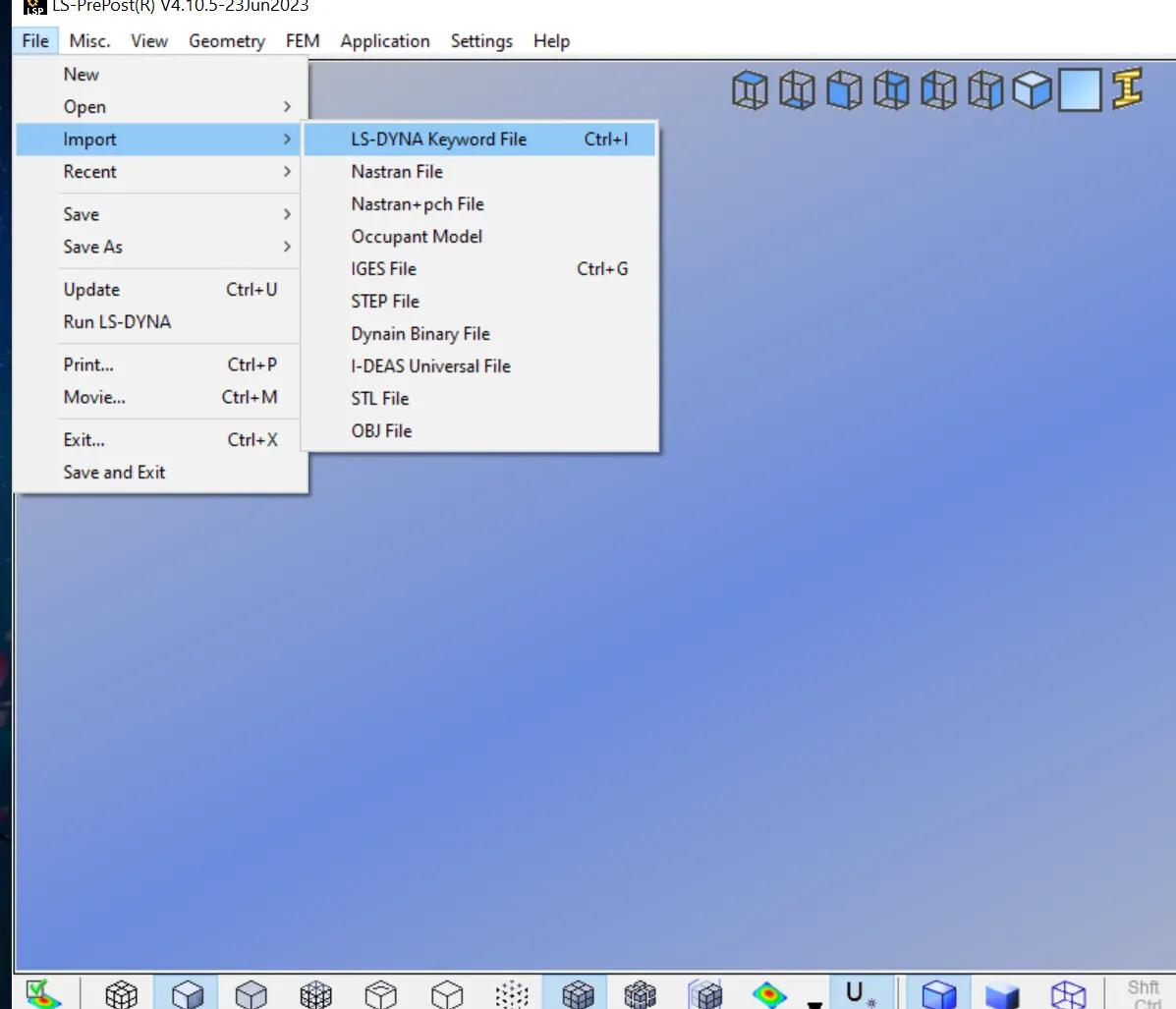
- First we open the .k file in the ls-pre post, using the option file>import>Ls-Dyna keyword file as shown below.
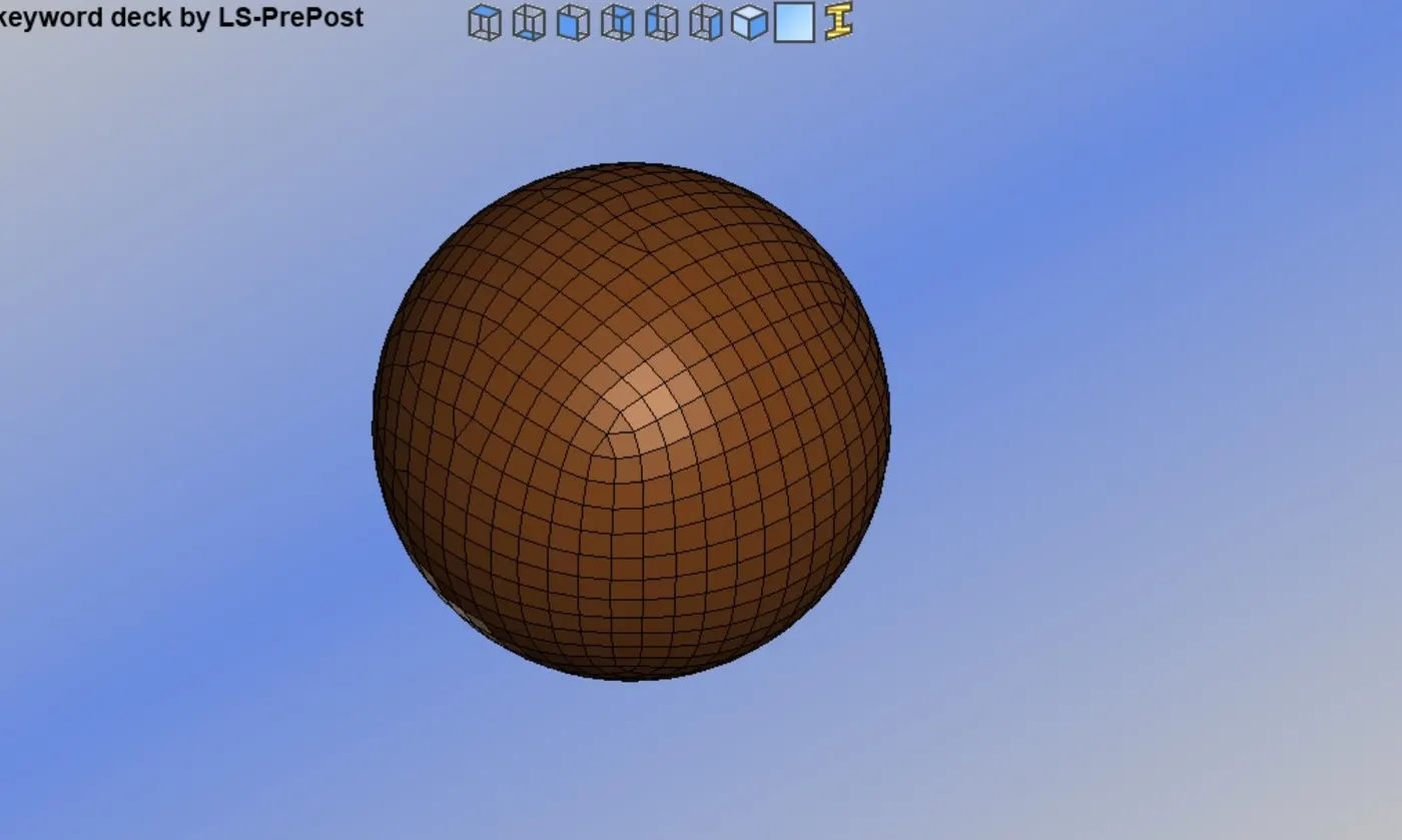
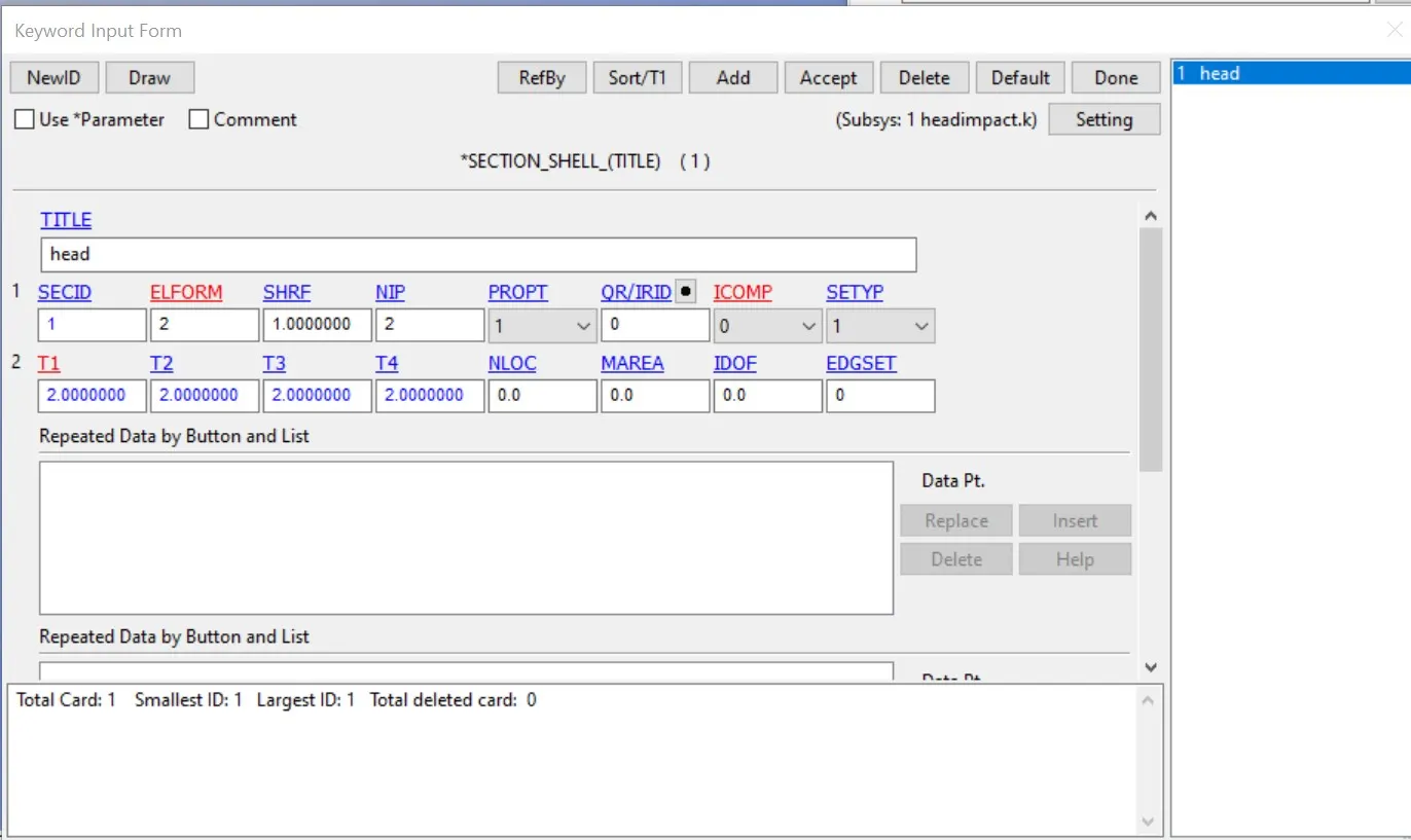
- Now we start with the section card, to create a section card from keyword>all>section>shell>here we will input id, elform type as shown below.
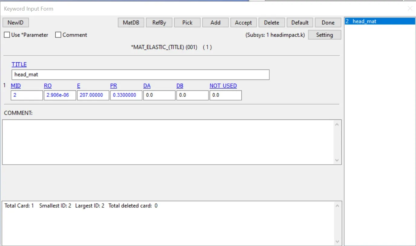
- Now we will create the mat card for it.
- Finally we have to assign the section and material to the part.
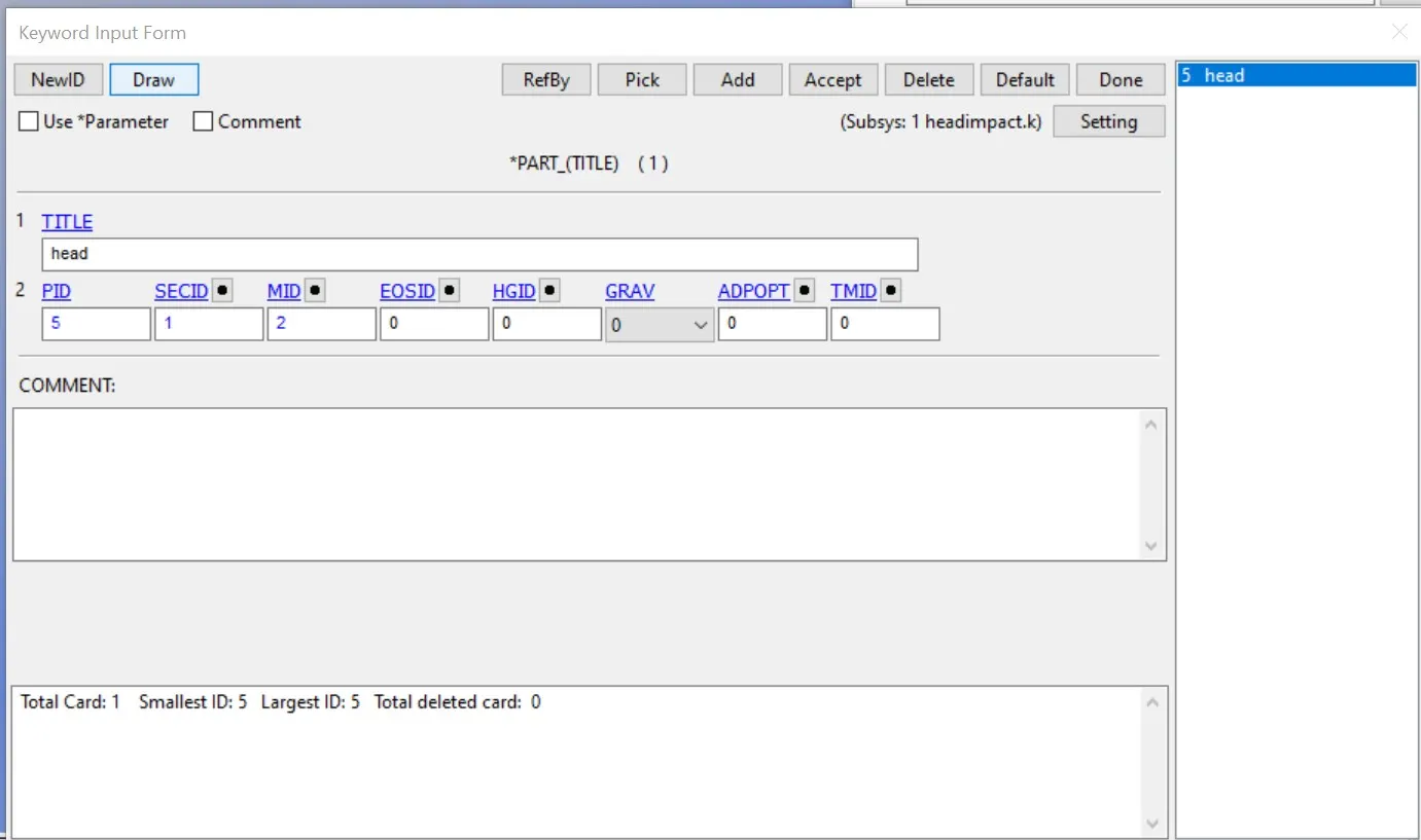
- Now we must create the rigid wall to impact the head model.
- To create the rigid wall go the created entity >rigid wall >select planer >goe-vector> 1n+nl.
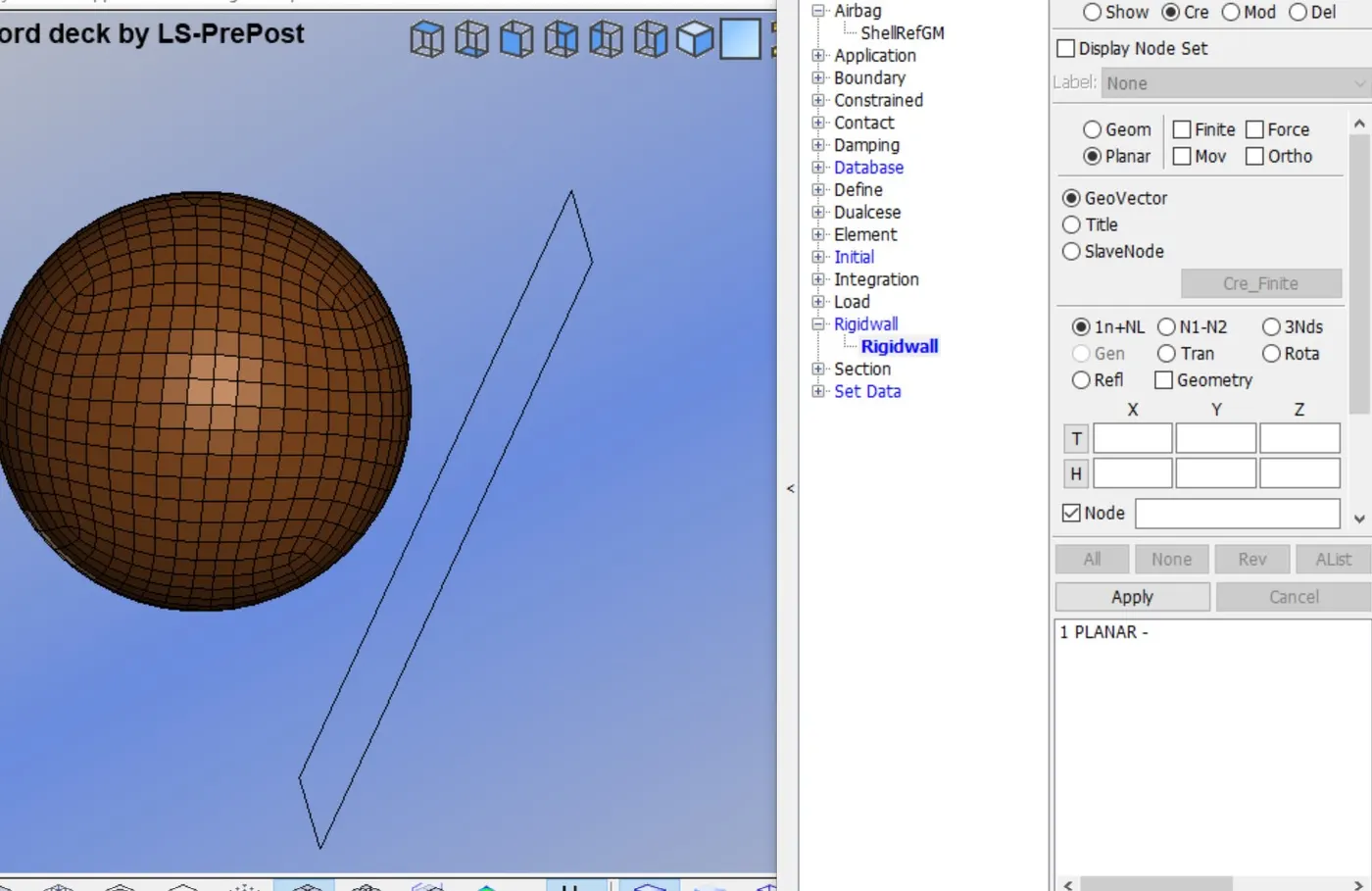
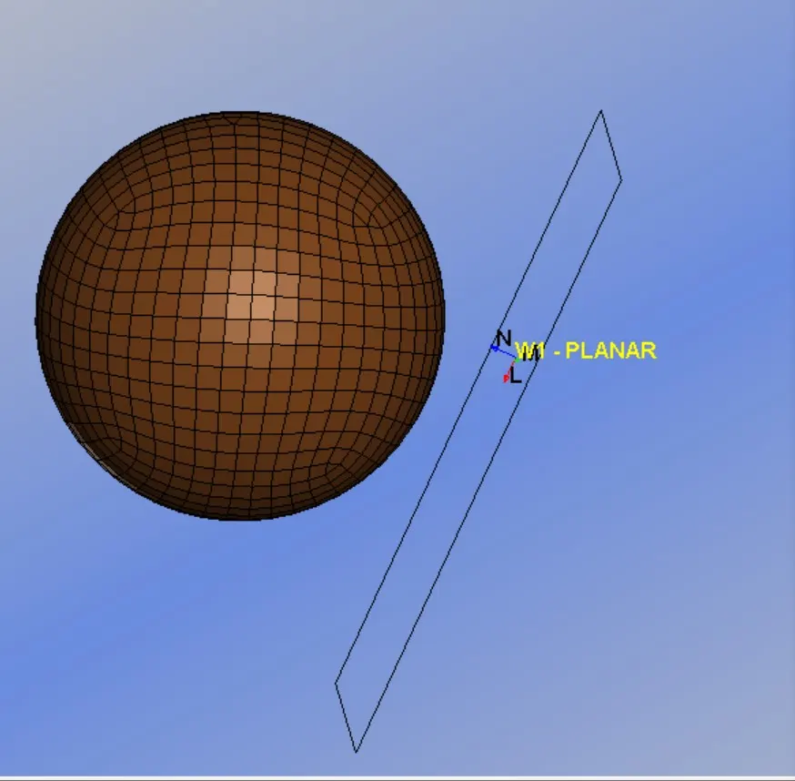
- now translate and rotate the rigid wall to some distance of 20mm in the direction of the velocity of the head model.
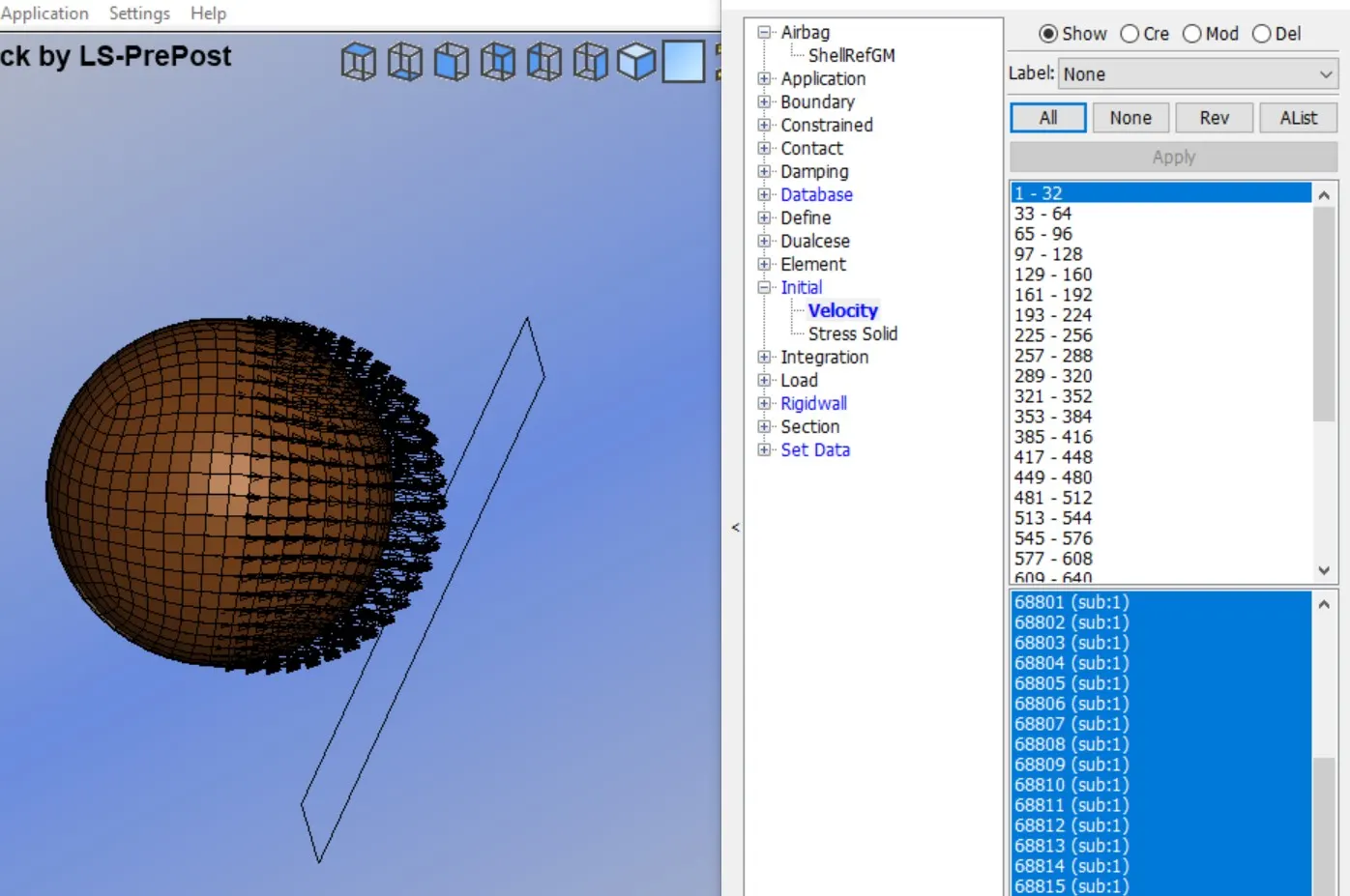
- The initial velocity is defined as the simple head foam to impact the rigid wall, we assume in this case the initial velocity is 40kmph i.e. -11.11mm/ms in the negative x-axis which is toward the rigid wall.
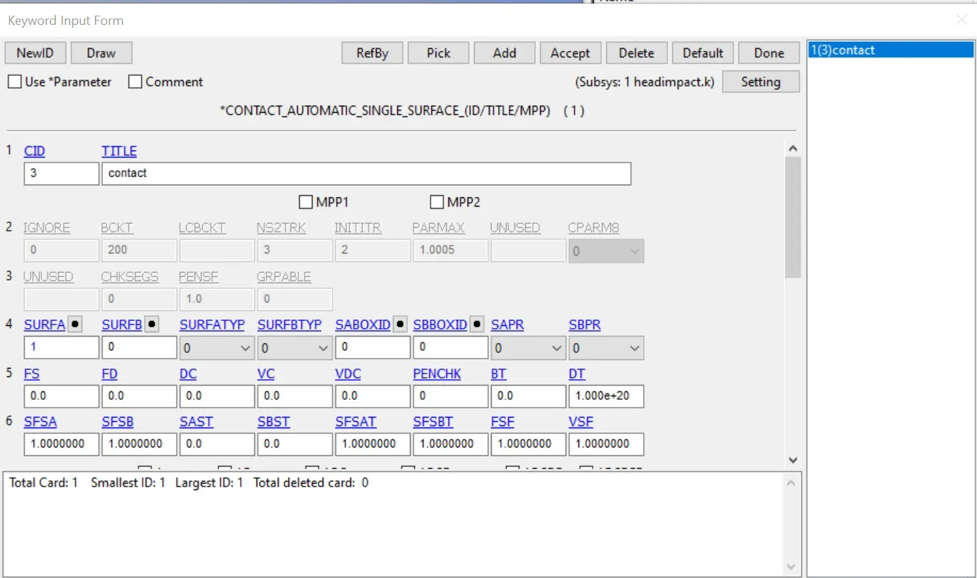
- Now we create the contact for the head, AUTOMATIC_SINGLE_SURFACE contact, here we have only selected the slave node no master will be present.
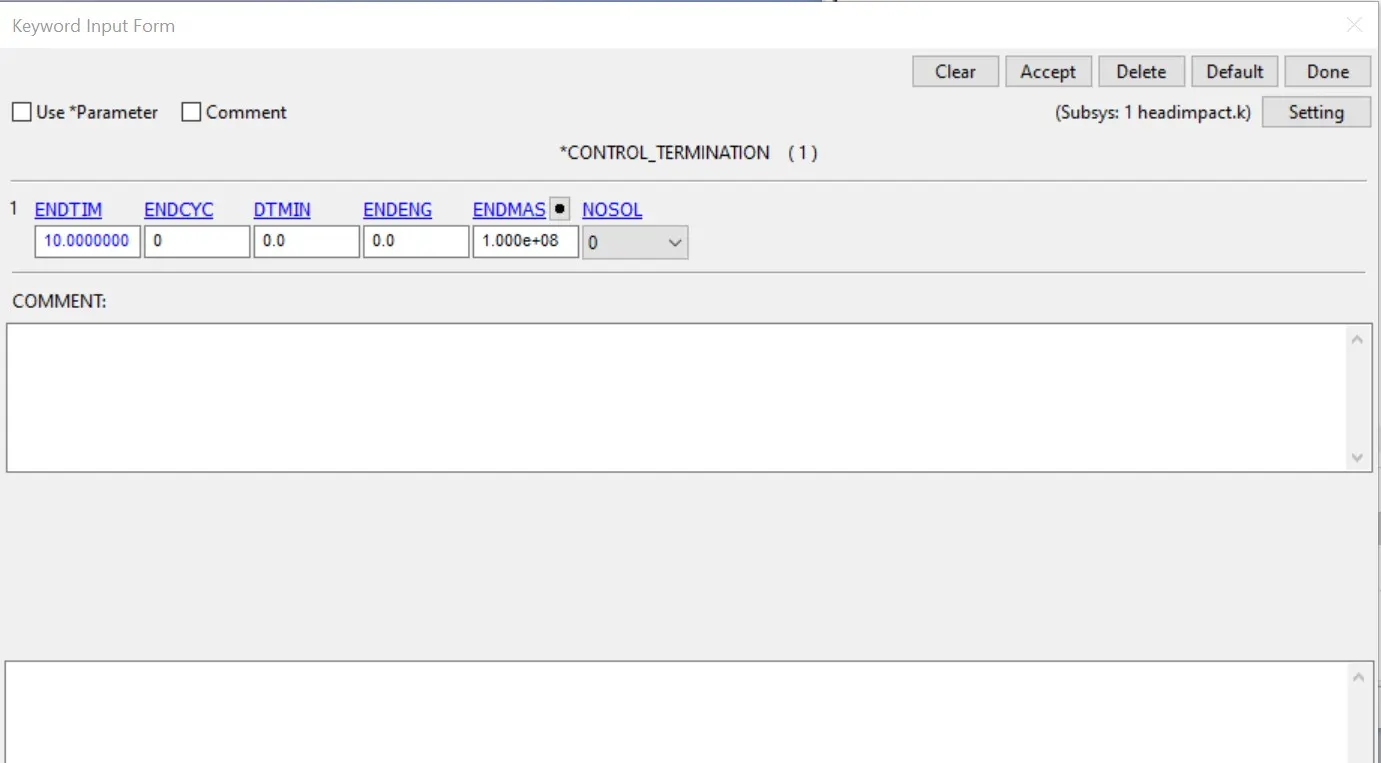
- Now we have to create the control cards for finalisation of output.
- first we will create a control_termination card.
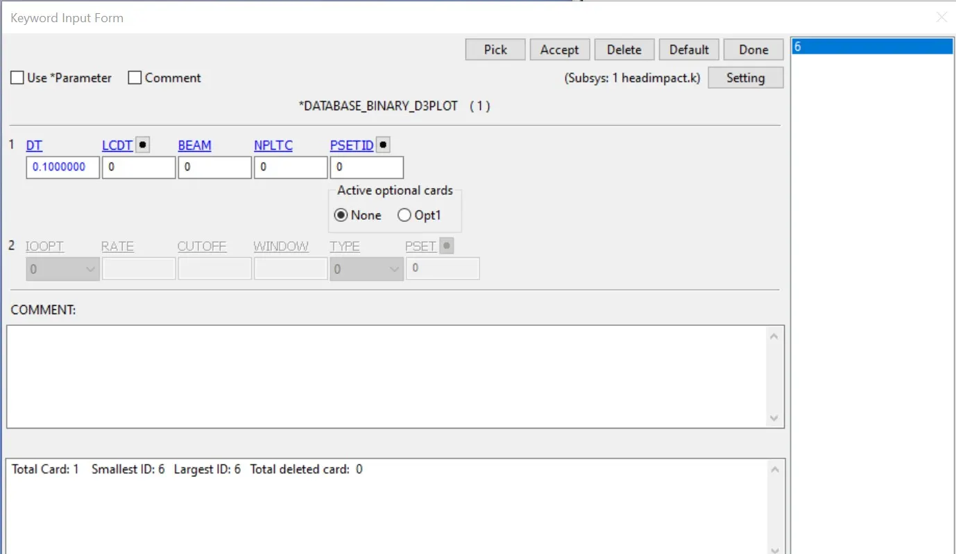
- Then we will create the database file.
- Binary_d3plot- it defines the frequency at which the animation file is to be created and is set to 0.1ms.
- database_history_nodes- A node on the right face of the head were defined to measure the acceleration and calculate the HIC value.
- Now we will create the ASCII file.
The output request is in ASCII format, The following keywords are activated.
- GLSTAT-Global data
- MATSUM-Material energies data
- NODOUT-Nodal point data
- RWFORC-Rigid wall force
- RCFORC-Resultant interface forces
- Now we will check the model and then head for simulation.
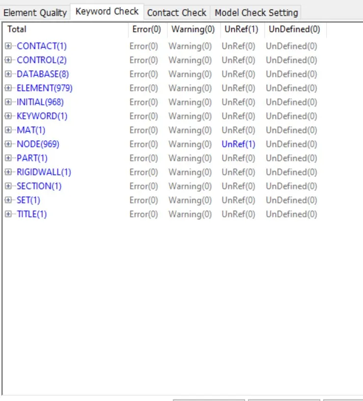
- since there is no error we can proceed to save and run the keyword file.
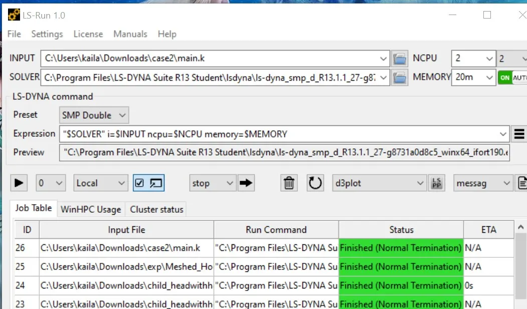
- As the simulation ended with normal termination. therefore, the model is simulated successfully.
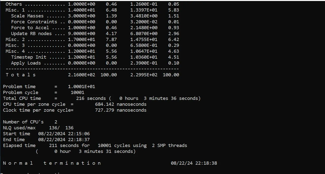
- Now open binary d3plot file in the ls-pre post.
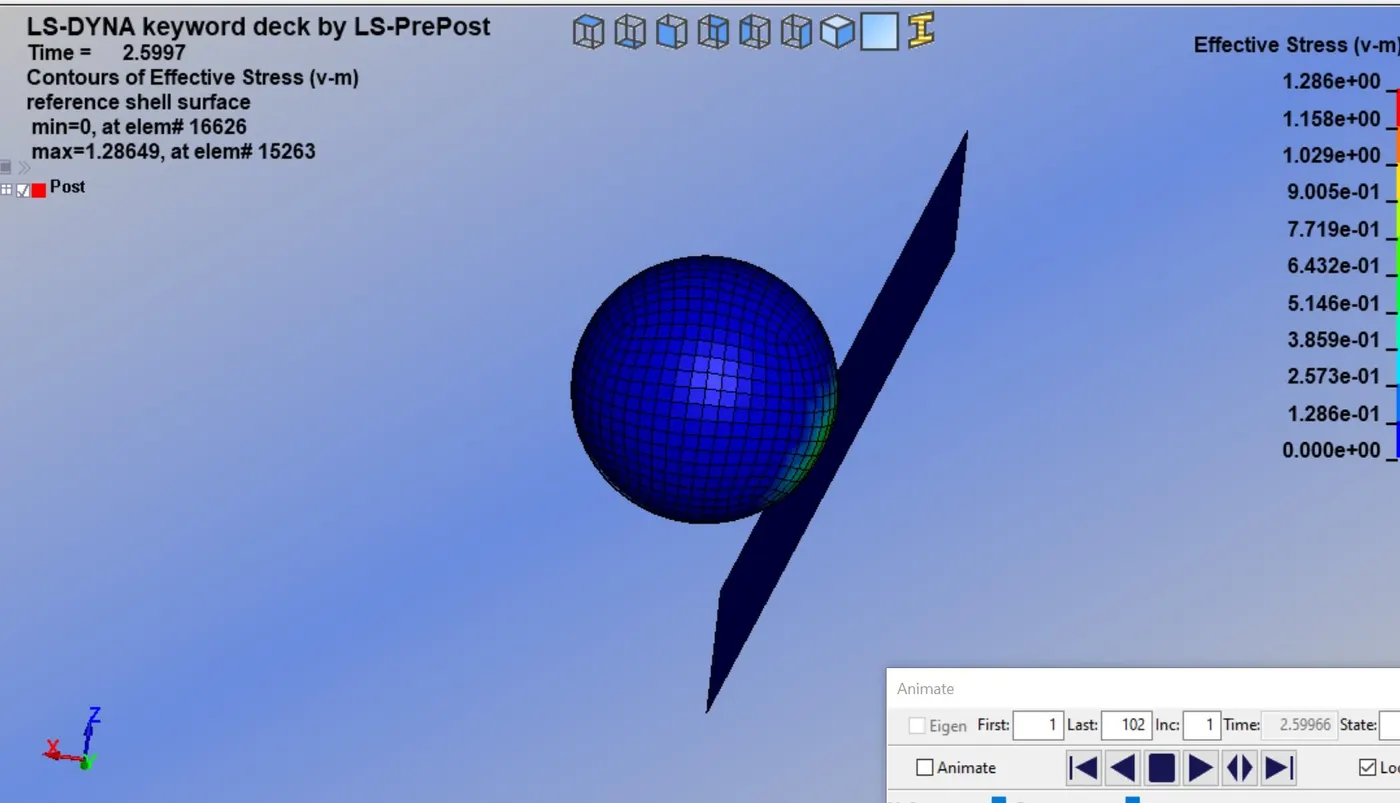
- maximum effective stress
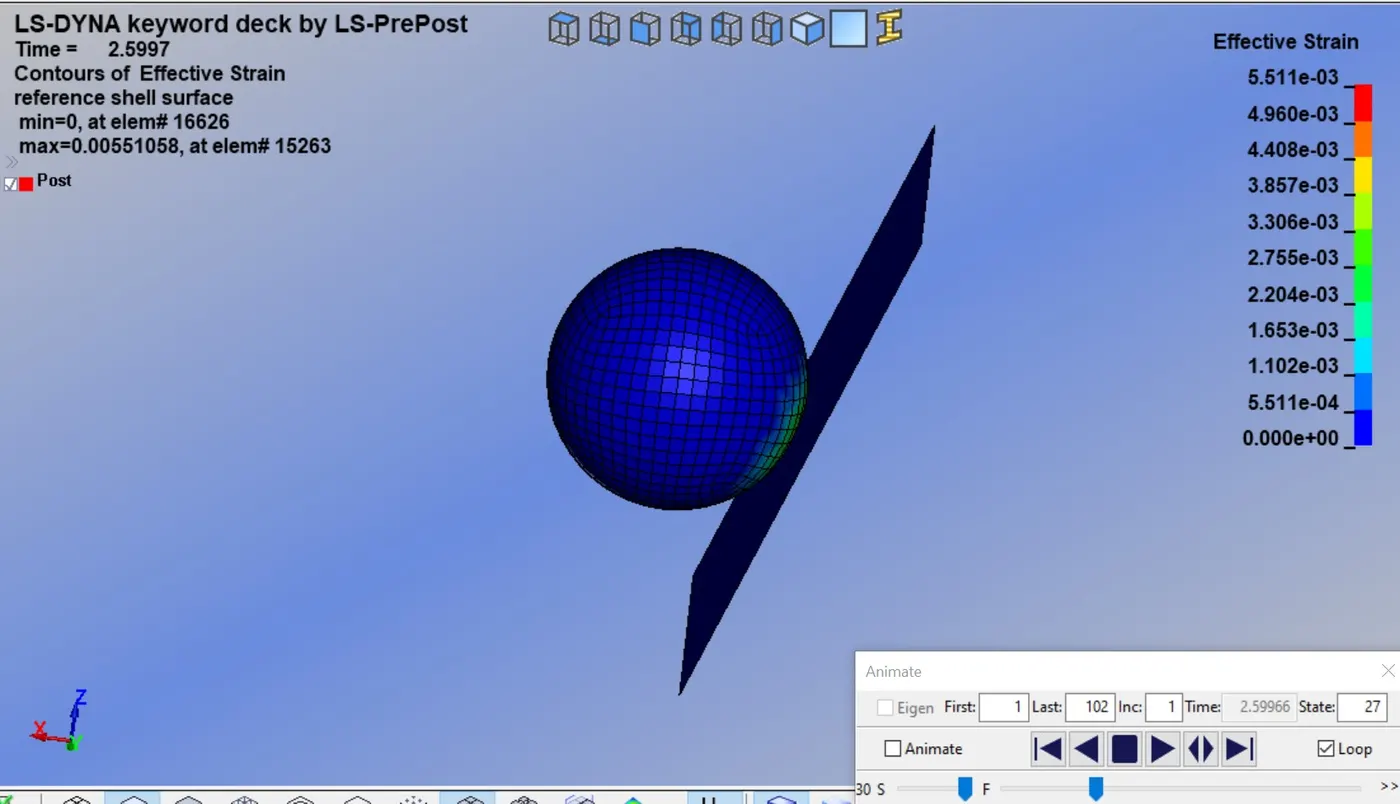
- maximum effective strain
- Energies graph
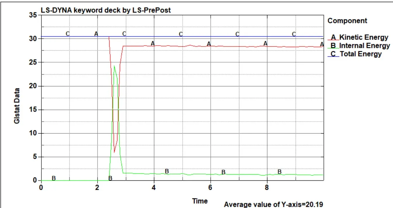
- In the above graph, we can see the kinetic energy decrease and internal energy increase at the instate of impact and they both meet around 15.15ms. This is due to the reduction of the velocity during impact. The simple head geometry brings elastic material, which bounces back without major loss of energy and attains velocity in other direction. This causes an increase in kinetic energy and a decrease in internal energy further and again they meet at around 15.10ms. The internal energy and kinetic energy remain constant.
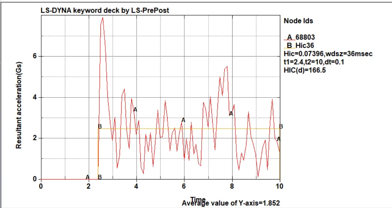
- Acceleration plot of the head test.
Case2:- child head-foam and rigid wall
The test setup is according to AIS 100. The release angle is 50 for the child's head foam. The child head foam velocity at impact is 11.11mm/ms (40km/h) for head foam. Here in this case impact point on the rigid wall instead of a car hood.
- First we open the ls-pre-post and create some cards which is necessary for simulation, first is the transformation of the original geometry is required to replicate the real impact situation. so the DEFINE_TRANSFORMATION card is used to rotate the original body about the y-axis, and the A1 to A6 direction cosines value.
- Here the INCLUDE_TRANSFORMATION is necessary for the file to be transformed and set up for analysis. In this card, the original geometry is called through the filename, and the defined transformation is carried out on the geometry. Transformation id (Tranid) is set to 1 for this card. The original input file has not been changed; it has only been called for transformation. now save this file like the head.k (main.k) file, close the ls-pre post, open the ls-pre post again, and open the main file.
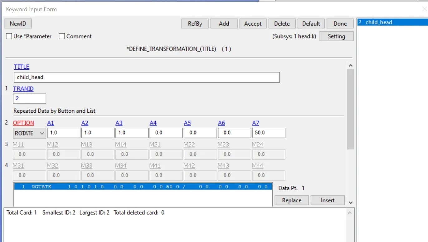
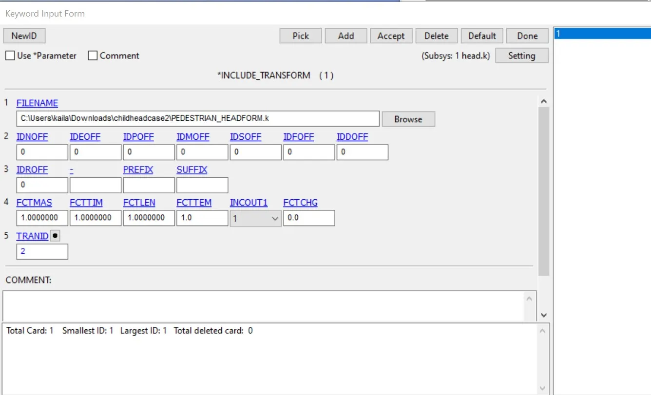
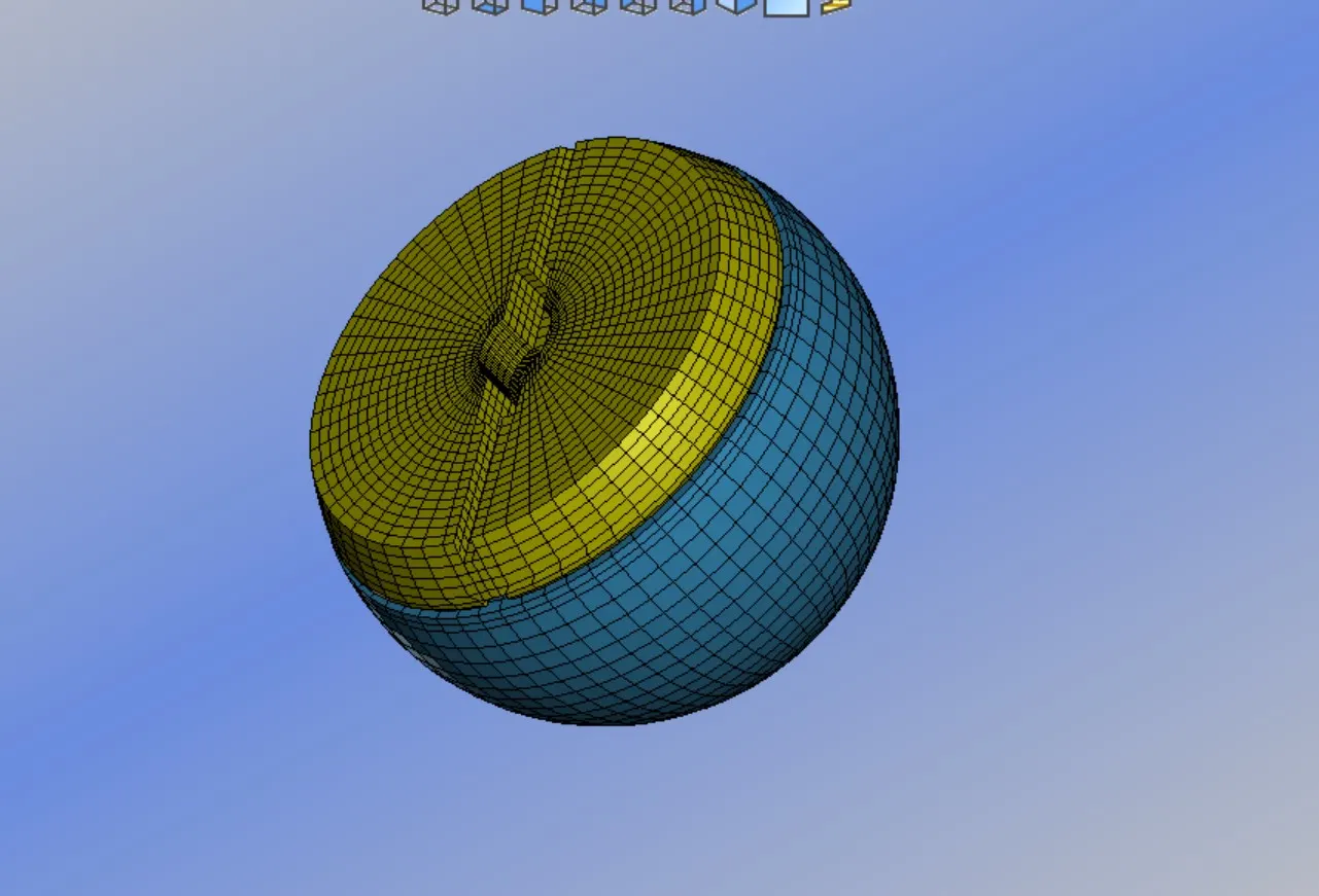
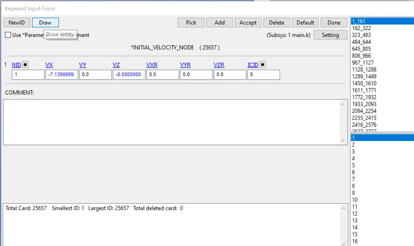
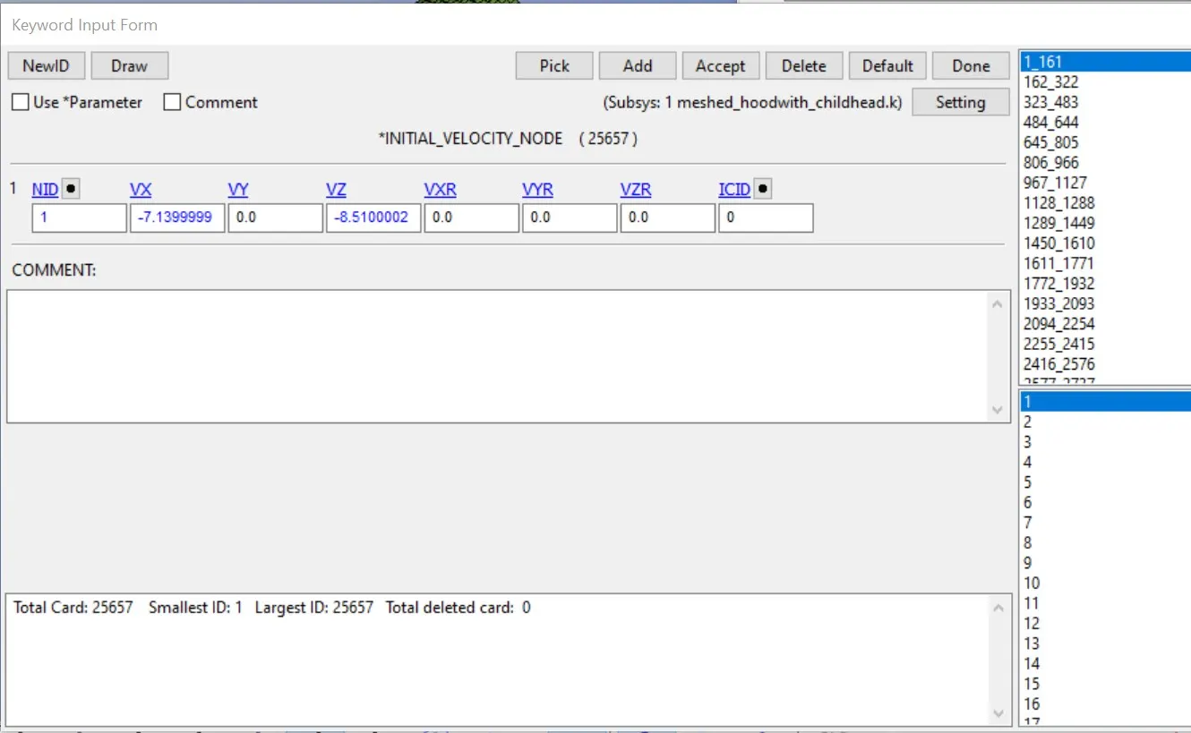
- As per Euro NCAP standards, the initial velocity is 40 kmph i.e. 11.11 mm/ms at an angle of 50. 11.11mm/ms is the resultant velocity so we do the components in the x and z direction, the vertical and horizontal components of the velocities are -7.14 mm/ms and -8.51 mm/ms respectively.
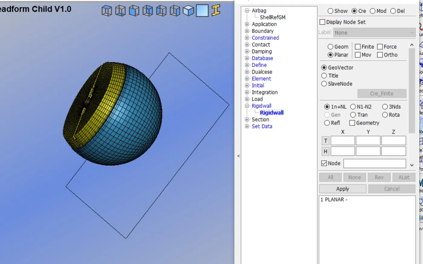
- The rigid wall is created at 20mm from the bottom of the standard dummy head foam model.
- Here are some of the cards like section, material, and contact definition cards already present as it is a standard model so we do not need to define that.
- so now we will define the control cards and database cards.
- we will define control_Energy cards and control_termination cards.
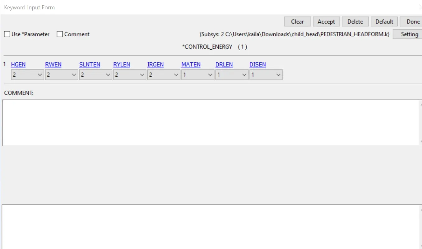
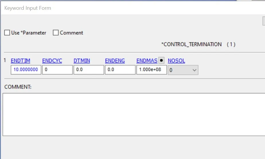
- Now we will create the database file.
- Binary_d3plot- it defines the frequency at which the animation file is to be created and is set to 0.1ms.
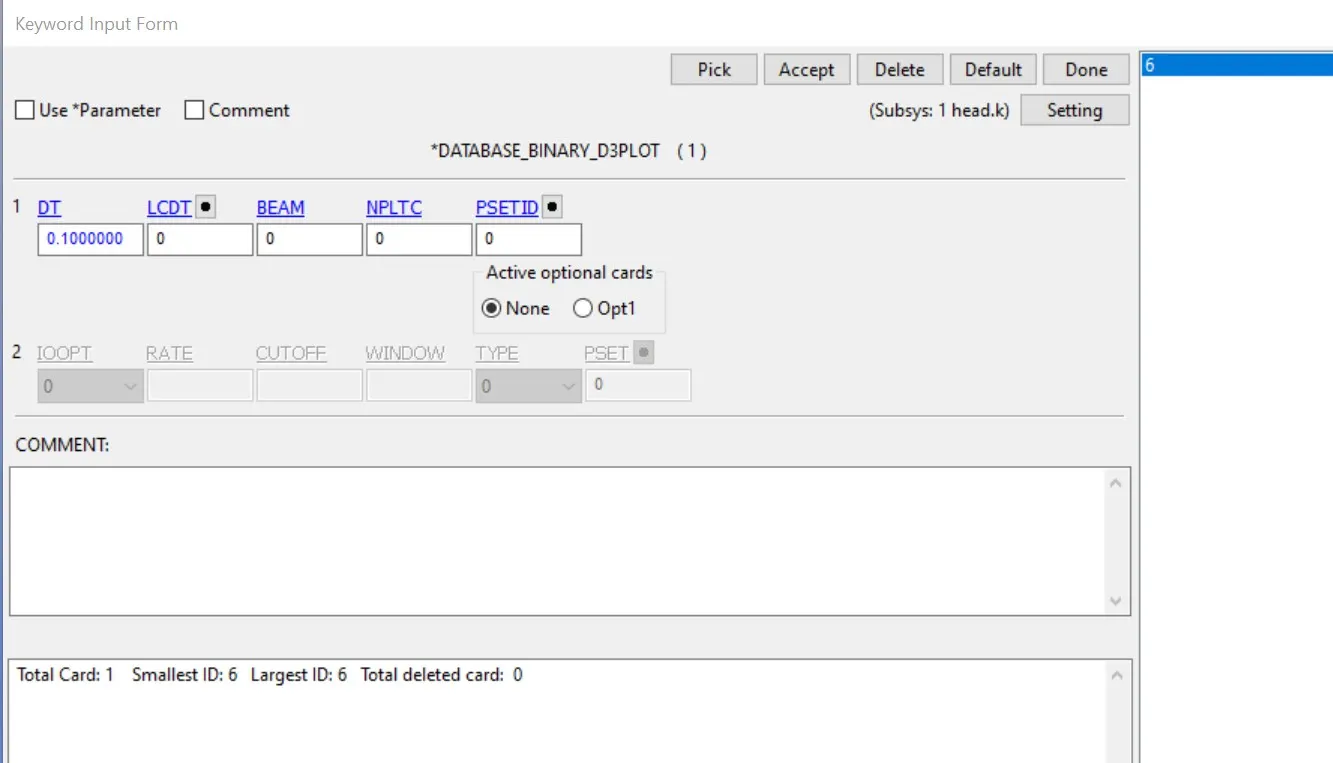
- database_history_nodes- A node on the right face of the head were defined to measure the acceleration and calculate the HIC value.
- Now we will create the ASCII file.
- GLSTAT-Global data
- MATSUM-Material energies data
- NODOUT-Nodal point data
- RWFORC-Rigid wall force
- RCFORC-Resultant interface forces
- Now we will check the model and then go for simulation.
The output request is in ASCII format, The following keywords are activated.
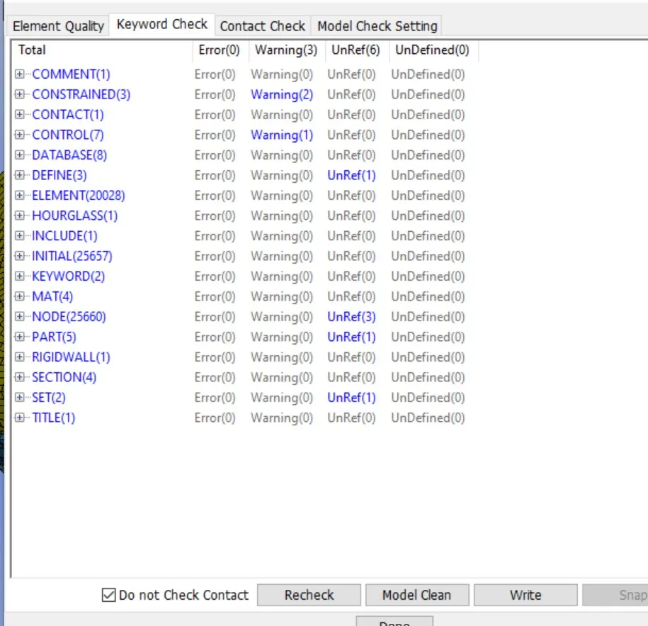
- since there is no error we can proceed to save and run the keyword file.
- Maximum effective stress
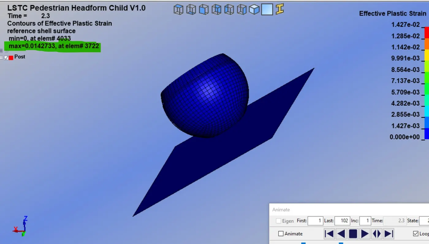
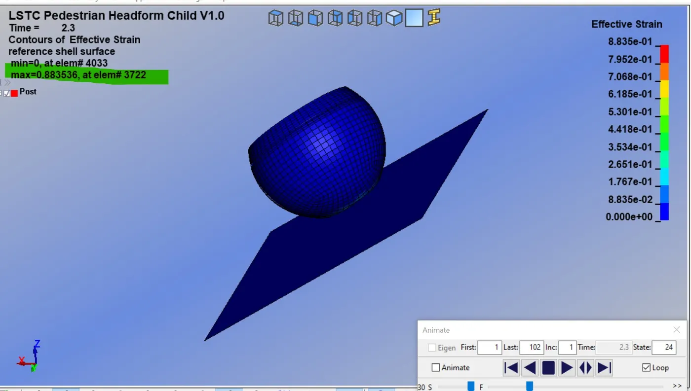
- Maximum strain
- Energies plot
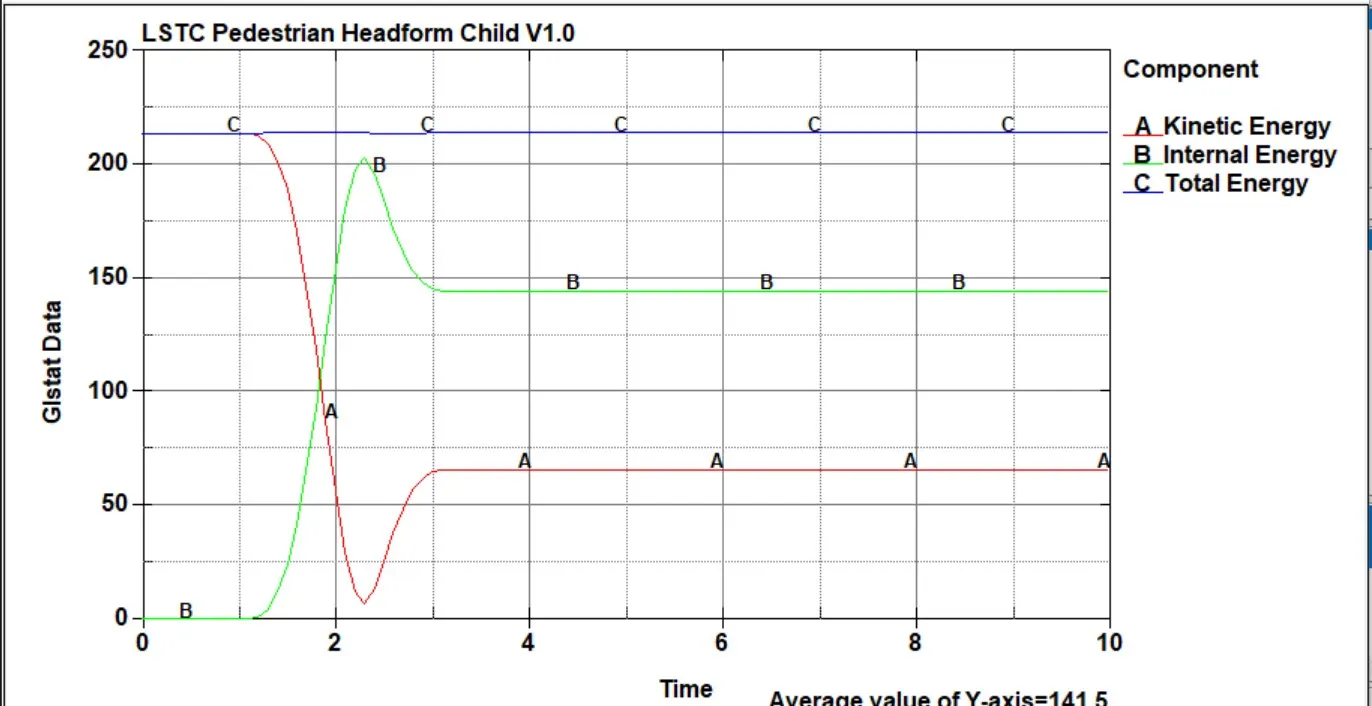
- From above the graph, we can see the kinetic energy decrease and internal energy increase at the impact at the instant of impact and they both meet at around 105.5ms and respectively it goes 54.3mm and 155mm, and again kinetic energy increase 93.9mm and internal energy decrease 117mm, after that it becomes constant. This is due to the reduction of the velocity during impact. since the head foam is molded with hyper-elastic material there some the energy is absorbed in deformation caused due to impact.
Case3:-child head-form and hood
- Here we will define the transformation card and we will create the main,k file for the child head foam like the previous case we will use DEFINE_TRANSFORMATION with release angle 50 and INCLUDE_TRANSFORM to define the position of the child head's head same as the last case close the ls-pre-post and open again.
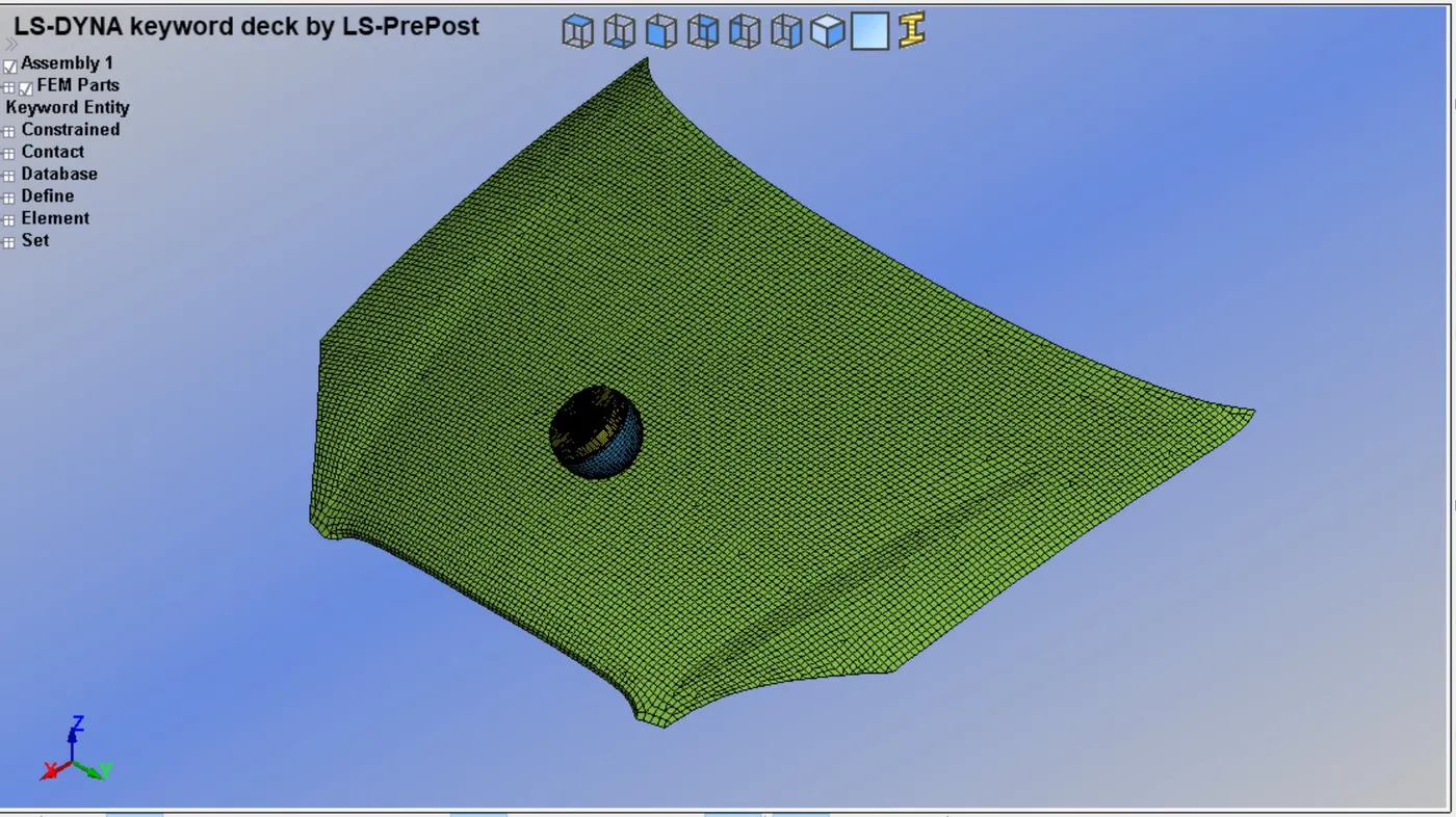
- In this case we will use a car hood instead of a rigid wall to study the real-life situation of a child pedestrian head impact simulation.
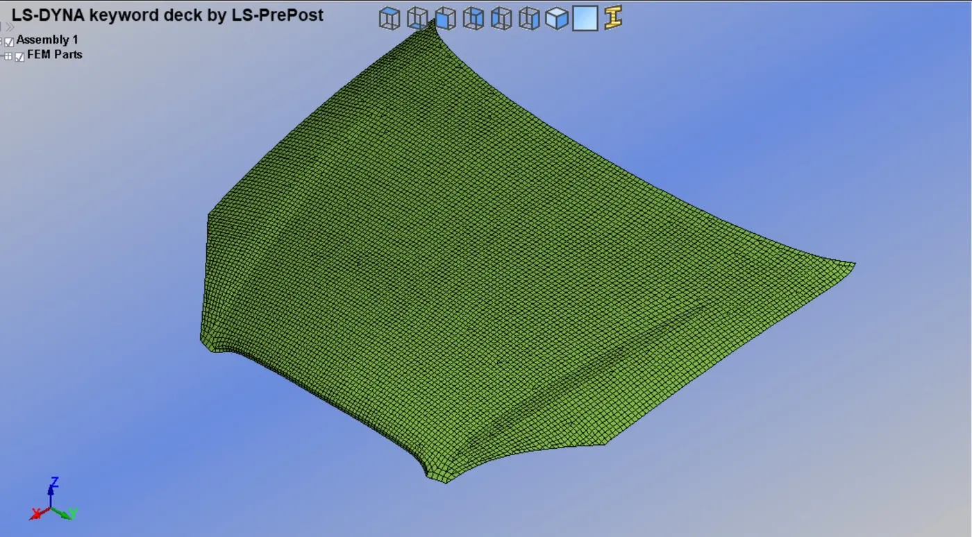
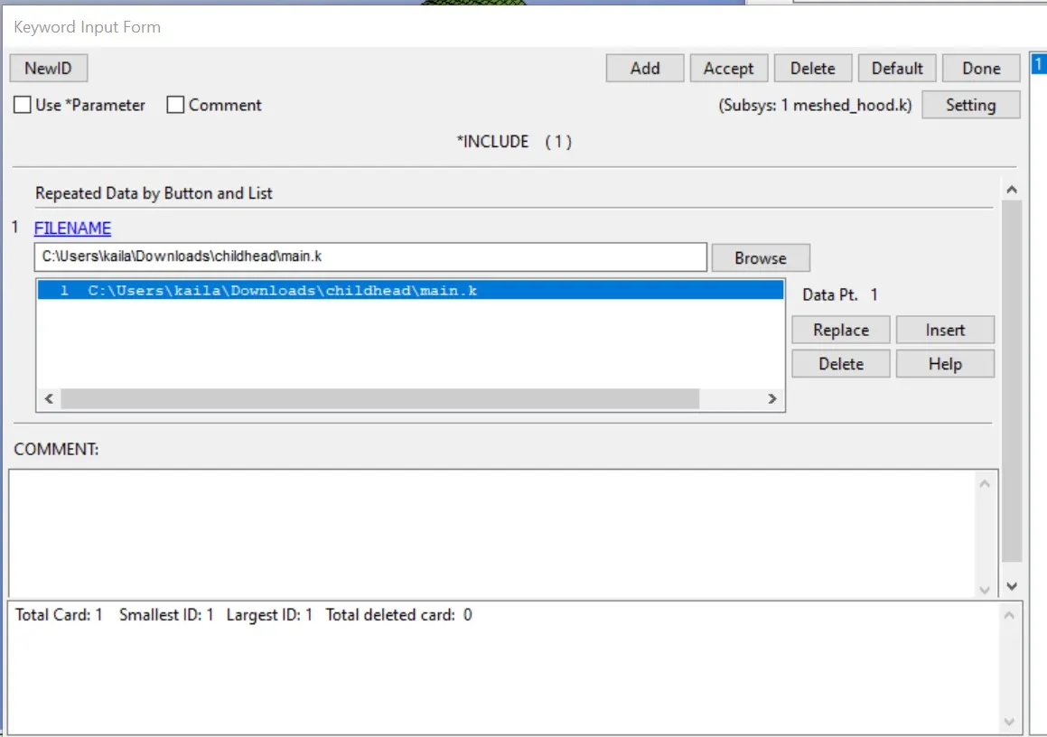
- First we will open the hood file, go *INCLUDE keyword, and assign the main.k file here and save it as meshed_hood.k file.
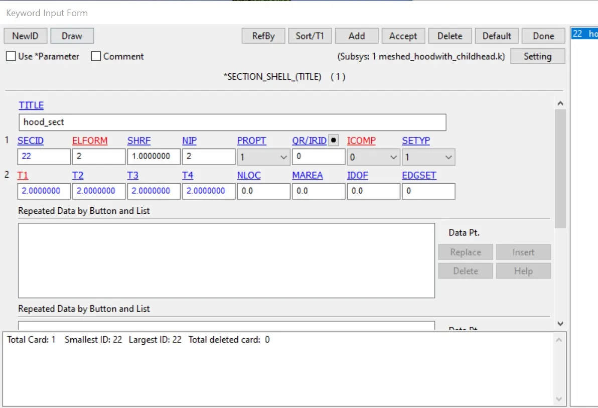
- Now open the meshed_hood.k file and start with the section card to create a section keyword>all>section>shell here we will input the id, elform id as shown below.
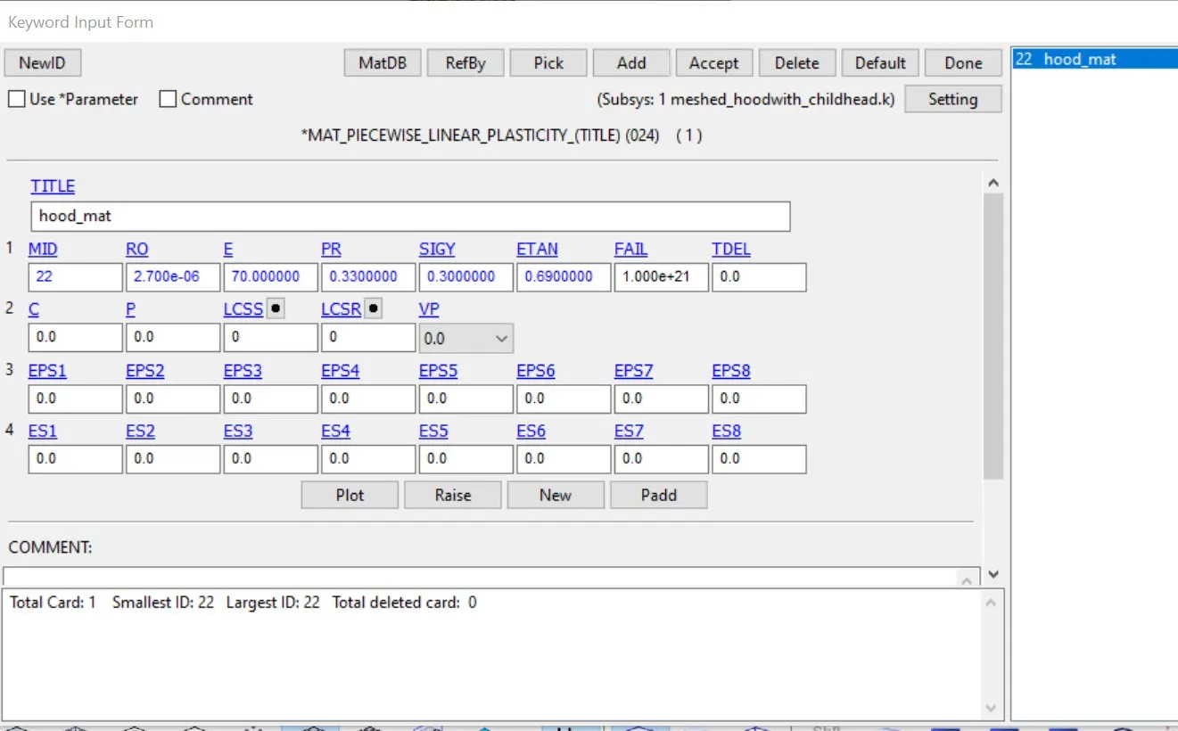
- Now we will create a mat card for the hood.
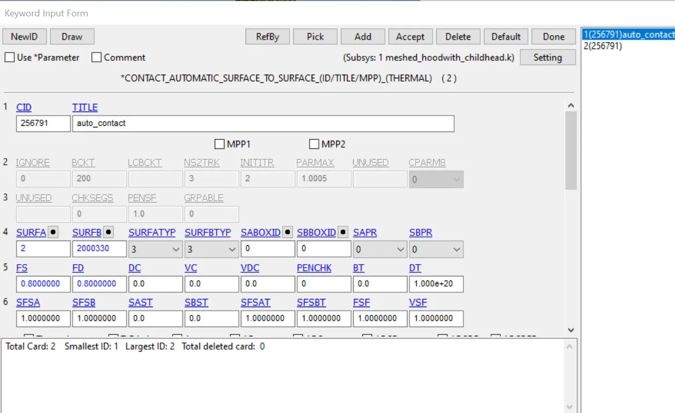
- To create contact we will use AUTOMATIC_SURFACE_TO_SURFACE contact has been defined between hood as master and head foam as slave. As the head foam has 5 components in it, the slave node-set type is given as part set id, and the hood as master segment type is also given as part set id.
- initial velocity is defined along x and z direction to the head foam to impact on the car hood. the initial velocity of 11.11 mm/ms is with which the head impacts the rigid wall but here it will be a resultant direction. So, the component motion in the negative x and z directions has to be calculated.
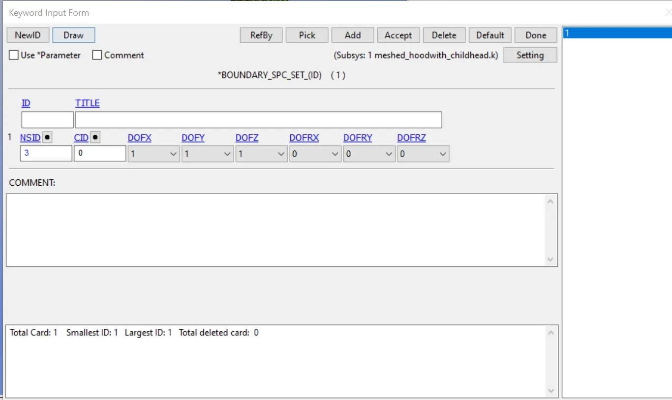
- The boundary SPC is defined for the hood to constrain and the degrees of freedom in translational for the set of nodes on the edges of the hood. restricted all rotational movement in all direction and accept the card.
- Here some of the cards like, section, material, and contact definition cards are already present as it is a standard model so we do not need to define that. (for head)
- so we will define the control cards and database cards.
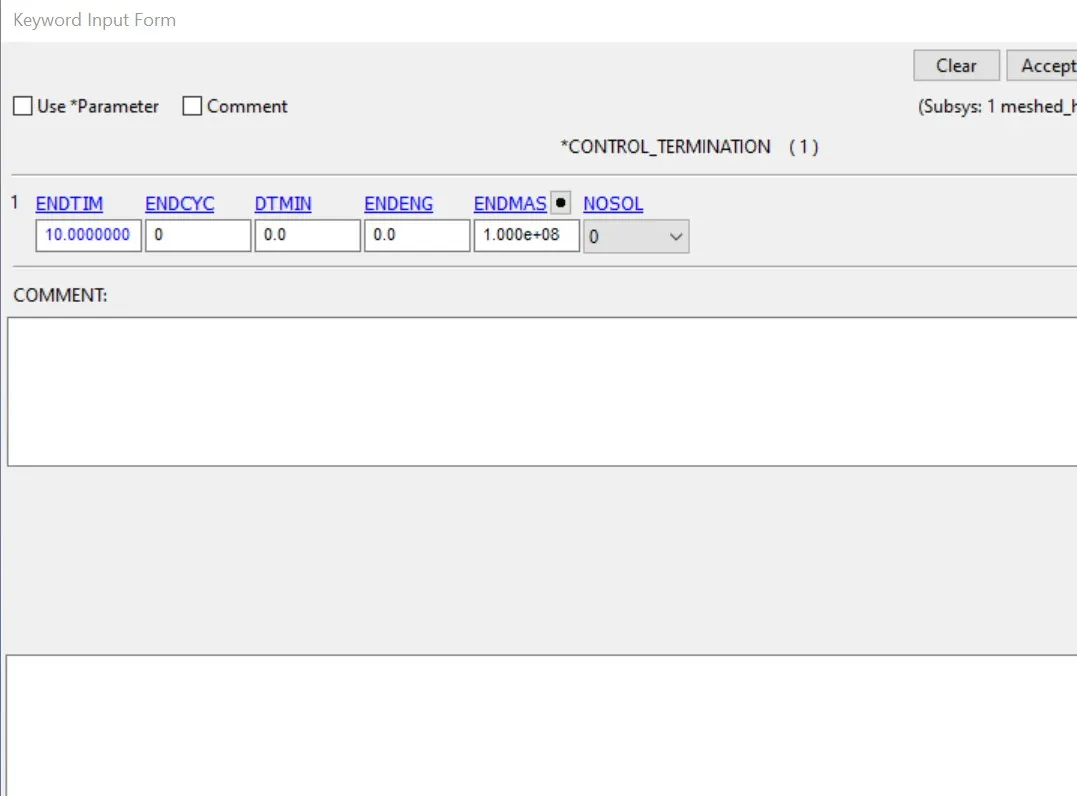
- we will define control energy and control termination cards.
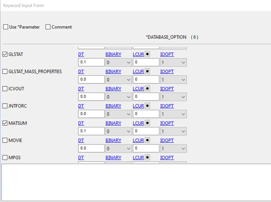
- GLSTAT-Global data
- MATSUM-Material energies data
- NODOUT-Nodal point data
- RWFORC-Rigid wall force
- RCFORC-Resultant interface forces
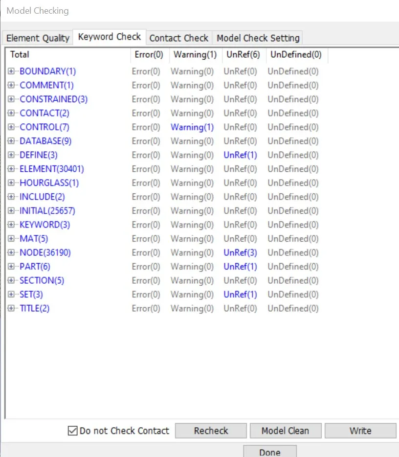
- Now we will check the model and go for simulation.
The output request is in ASCII format, The following keywords are activated.
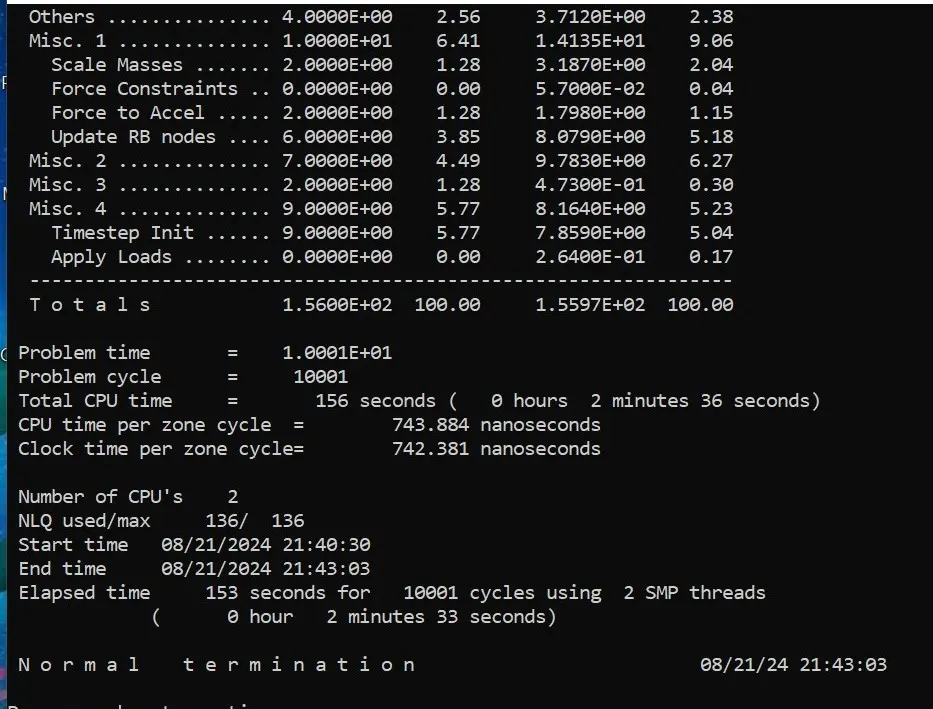
- Now we will run the simulation and plot the result.
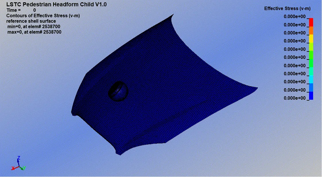
- Maximum effective stress.
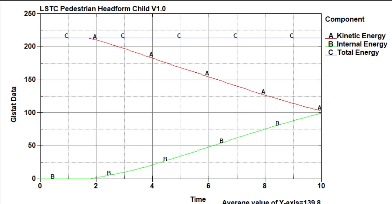
- Energies plots
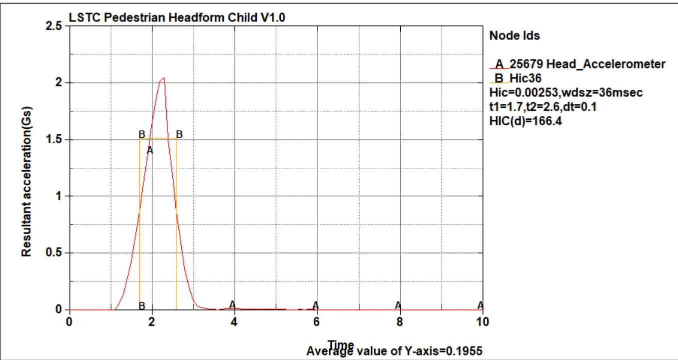
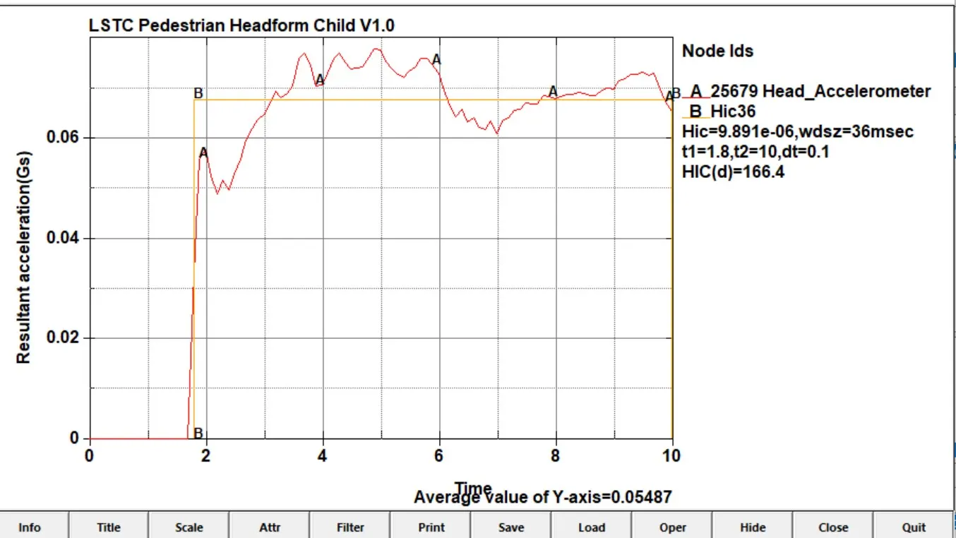
- Acceleration plots.
Conclusion:-
- The simple head model was defined with MAT_ELASTIC material cards which implies the material is pure elastic that's why the maximum stress is only there in the time of the impact there is no significant deformation in the simple head geometry. due to this HIC value is very high.
- In the second case the proper material card is used with child head that is ogden_rubber. since the rigid wall is un deformed so the total stress is transferred to the head and deforms the head geometry and the HIC value is lower than case 1.
- In this case we used a car hood to study the real-life situation the hood was defined with a piecewise linear plasticity material model, which is a deformable model so during the impact the hood deforms significantly and reduces stress and strain on the head foam and thuse reduce the HIC values and value is lower than case 2.