Week-7 Head Impact
Objective:
To perform a Head impact analysis on a child pedestrian head using LS PREPOST and calculate the Head Injury Criterion (HIC) for different cases.
Theory:
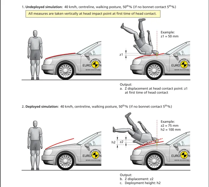
Pedestrian safety simulation is a part of vehicle safety engineering, In pedestrian safety we look for imparting minimum injury to body parts such as head and legs ( Upper thigh & Knee ) usually these test are done at a minimum velocity ranging from 20-40 kmph since the driver usually apply breaks during the impact, HIC(Head injury criteria/coefficient) is a measure of the possibility of severity the head injury caused due to the impact after an accident. This is basically a measure of average acceleration during a small interval of the crash.
Head Injury Criterion (HIC):
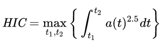
where t1 and t2 are the initial and final times (in seconds) chosen to maximize HIC, and acceleration is measured in gs . The time duration, t2 – t1, is limited to a maximum value of 36 ms, usually 15 ms.
This means that the HIC includes the effects of head acceleration and the duration of the acceleration. Large accelerations may be tolerated for very short times.
At a HIC of 1000, there is an 18% probability of a severe head injury, a 55% probability of a serious injury and a 90% probability of a moderate head injury to the average adult.
Head foam impactors are used to test the behavior of vehicle structures such as the hood. In a pedestrian-vehicle impact, the kinematics and severity of pedestrian injuries are affected by the impact locations on the vehicle and body velocities after impact. The objective of this project is to analyze the pedestrian kinematics in a Pedestrian-Car accident scenario and determine the Head Injury Criteria (HIC) from the head resultant acceleration, for head impacts on the vehicle hood.
Procedure:
Case setup & Execution:
Case 1: Simple Head Impact on rigid wall
1. Importing the keyword file
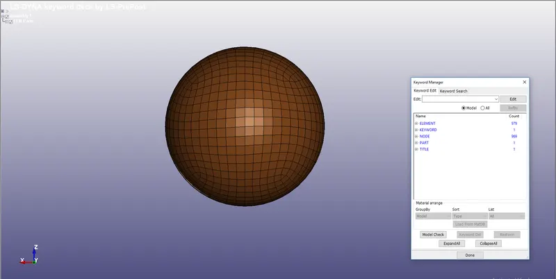
- The given keyword Simple_Head_model.k is opened in LS PREPOST .
- The file consists only of nodes and elements of shell, to perform the simulation other important parameters are needed to be defined.
- The Unit Kg/mm/ms is followed throughout the Analysis.
2. Assigning the material:
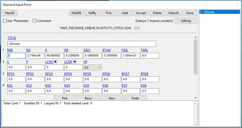
- For assigining the material the following steps are followed Keyword manager `rarr`All `rarr`Mat `rarr` Select the material card, here different material properties like mass density, youngs modulus, poisson's ratio and other recommended values are given
- Mat_24_Piecewise_Linear_Plasticity card with properties of silicone assigned.
3.Section creation:
- Shell section is needed to be defined by selecting Keyword manager `rarr`All `rarr`Section `rarr`Shell
- Here the shell selection with element formulation 2 is defined with the thickness is given as 2mm
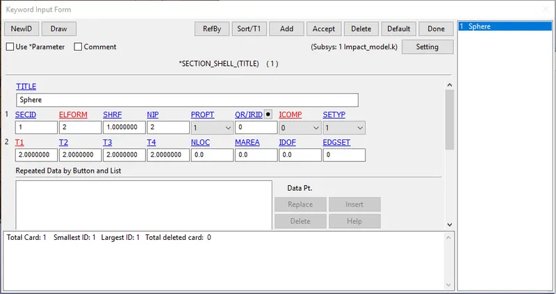
Specifying section and materials to their respective part ID's
- For creating the part Keyword manager `rarr`model `rarr` part is used , then the respective section and material is assigned to it.
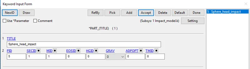
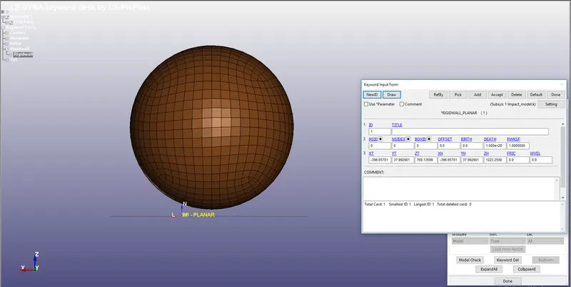
4. Rigid wall creation:
- The Simple head model must impact to a rigid wall
- The Rigid wall is created normal to the Z-axis which can be created by using the following commands
- Create entity `rarr`Rigid wall `rarr`Planar `rarr`NZ `rarr`Pick any node `rarr`apply
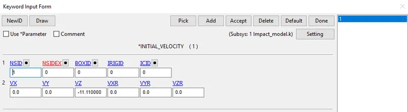
5. Boundary conditions:
Initial velocity:
- Initial velocity is defined to the phone by Keyword manager `rarr`New `rarr` Initial `rarr` Velocity
- A velocity of 11.11 mm/ms (40kmph) is assigned to all the Nodes in the Part along the negative Z axis.
6.CONTACT INTERFACE:
- Since the wall Created is Rigid Here, it acts as Master in Nature, So Automatic Single surface Contact is created defining Head Model (sphere) as a slave.
- The slave segment type (SSTYP) is defined by the Part IDs, select the simple head as Slave.
- All other Parameters are given as default
7. CONTROL CARDS:
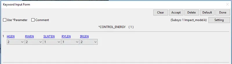
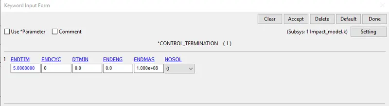
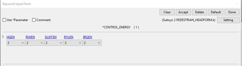
- Control cards such as control energy which is used to specify the control of hourglass energy and control termination which controls the termination of the end time of simulation are specified here
- Keyword manager `rarr`All`rarr` control `rarr` Energy/Termination command is used to define control energy and control termination
8. Output Request:
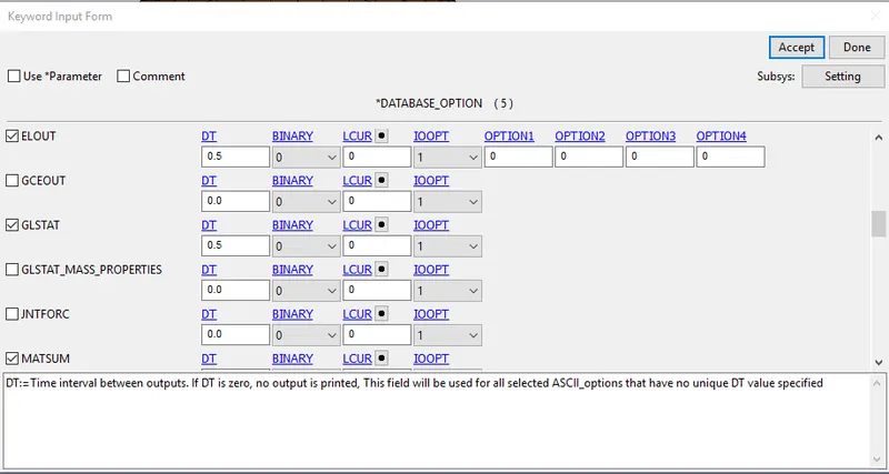
- Generally output resquest are specified to view the results of the simulation which is done by the following commands
- Keyword manager `rarr`All`rarr` Database`rarr` ASCII_option from which GLSTAT,MATSUM,NODOUt option is selected with DT= 0.5 ms
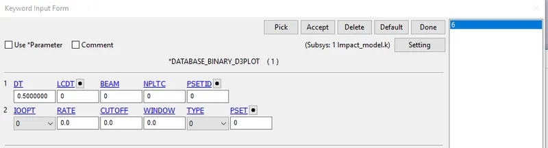
BINARY_D3PLOT: It defines the frequency at which the animation file is to be created and is set to 0.5
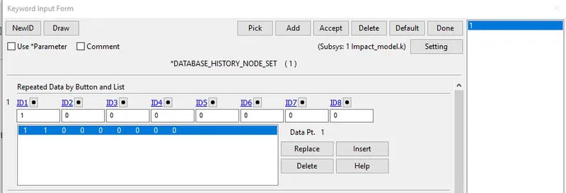
DATABASE_HISTORY_NODE: A set of nodes created Below the Head where It will impact to measure the acceleration And HIC value
9. Run the simulation
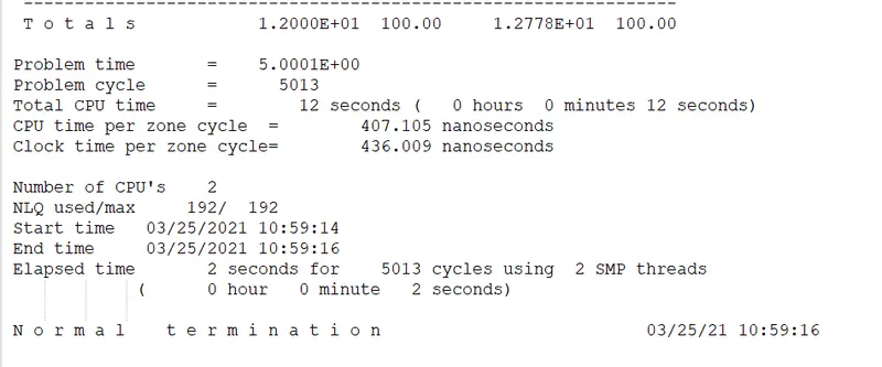
- The keyword is saved in a separate folder and it is opened in Ls-Dyna manager
Results:
Effective stress:
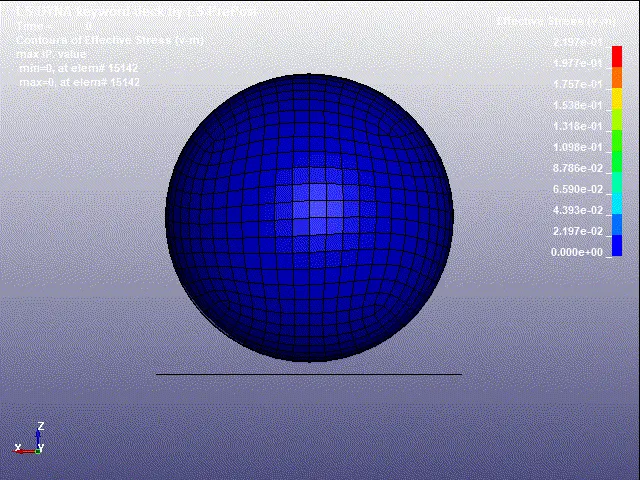
- The Maximum Stress acting On the Head is 2.197 pa at element 15345
- The Minimum Stress acting On the Head is 0.000 at element 16626
Effective strain:
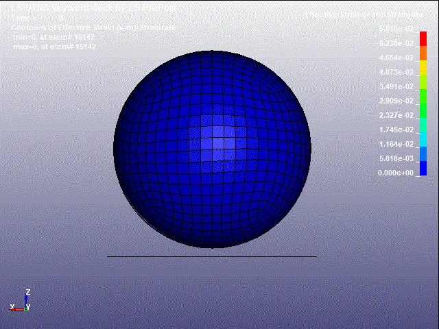
From the simulation it is noted that the maximum strain is 0.05818
Graph:
1.Energy graph:
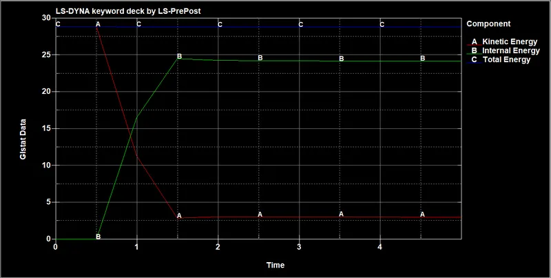
- From The graph, we can see that Total energy Is In a straight line as it satisfies the Law of Conservation of energy, as the Internal Energy produced from the wall is equal to the Kinetic energy of the Head impacting On the wall.
- The Kinetic energy is constant till 0.5ms And after the impact decreasing Gradually.
- Similarly, the Internal energy rises at the same moment when the impact has happened
2. Acceleration and HIC graph:
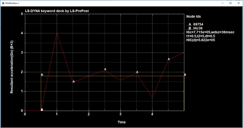
Since there is No accelerometer Placed a Random node selected Based on the Impact and HIC value is Plotted
HIC=7.715 e+05: average calculated between 0.5 ms to 5 ms
Case 2: Pedestrian head form impact on the rigid wall:
1. Importing the model:
- The given keyword PEDESTRIAN_HEADFORM.k is opened in LS PREPOST .
- The Angle of Impact of the Headform Must be within 35-75 degrees and the Speed of the Impact Should be 40kmph (11.11mm/ms)
- here we can see that the sphere is exactly 90 deg with respect to Z axis considering x and y as base
- The given condition is that the pedestrian head should be with in an angle of 35-75 degrees we need to transform this file as follows.
`implies` Since the Transformation of original Geometry Is necessary To replicate the Solution Like real-time Impact *DEFINE_TRANSFORMATION
`implies`A new keyword file Is created for the Rotation of the Headform Using the *DEFINE_TRANSFORMATION car
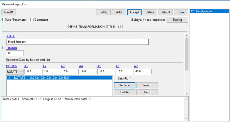
- Give TRANID as 1 and Choose Rotation as Option
- The head form is rotated Along Y-axis at an angle of 45deg
`implies` *INCLUDE_TRANSFORM card is used to Complete the Rotation Process.
`implies` While defining *INCLUDE_TRANSFORM
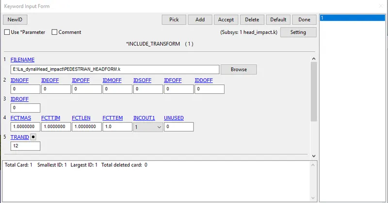
The Keyword is saved in the same Folder Where the Original Geometry Is Saved.
Both *INCLUDE_TRANSFORM and *
Now the keyword file with *INCLUDE_TRANSFORM and *
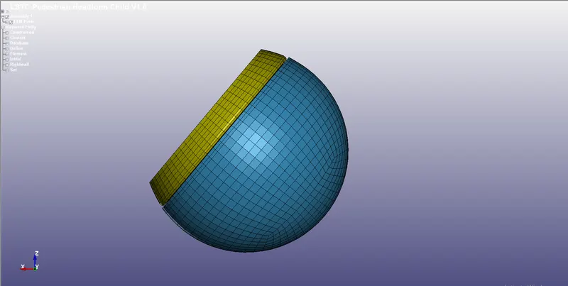
Here we can notice that the head is inclined at an angle of 45 deg from Z axis.
The key word file already contains important keywords like material,section and contact interface for the pedestrian head form we can proceed to give boundary conditions, output requests and other important parameters to extract the solution.
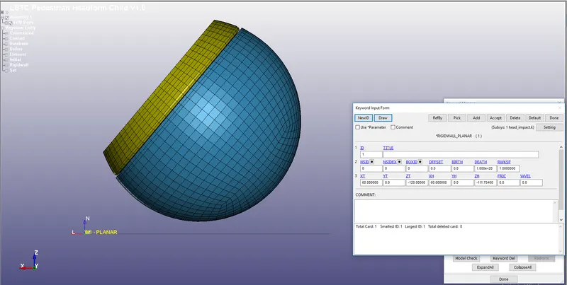
2. Rigid wall creation:
- The Pedestrian head form must impact to a rigid wall
- The Rigid wall is created normal to the Z-axis which can be created by using the following commands
- Create entity `rarr`Rigid wall `rarr`Planar `rarr`NZ `rarr`Pick any node `rarr`apply
3. Initial velocity:
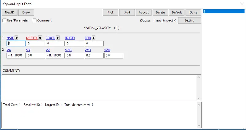
Since the Model is rotated to a certain angle the velocity should be resolved according to the axis
here the angle of rotation is 45 deg,
`implies``V_x`= 11.11 cos 45
`implies``V_z`= 11.11 sin 45
The resolved velocity is 7.5mm/ms since its acting in a negative direction -7.50mm/ms is defined for both `V_x`& `V_z`
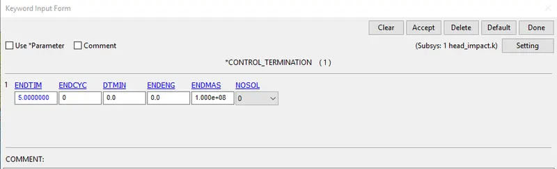
4. CONTROL CARDS:
- Control cards such as control energy which is used to specify the control of hourglass energy and control termination which controls the termination of the end time of simulation are specified here
- Keyword manager `rarr`All`rarr` control `rarr` Energy/Termination command is used to define control energy and control termination also there are already predefined cards like Accuracy, Bulk_viscosity, Output and time_step are present.
5. Output Request:
- Generally output resquest are specified to view the results of the simulation which is done by the following commands
- Keyword manager `rarr`All`rarr` Database`rarr` ASCII_option from which GLSTAT,MATSUM,NODOUt option is selected with DT= 0.5 ms
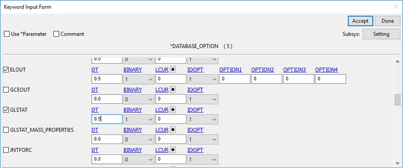
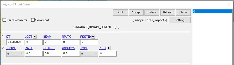
BINARY_D3PLOT: It defines the frequency at which the animation file is to be created and is set to 0.5
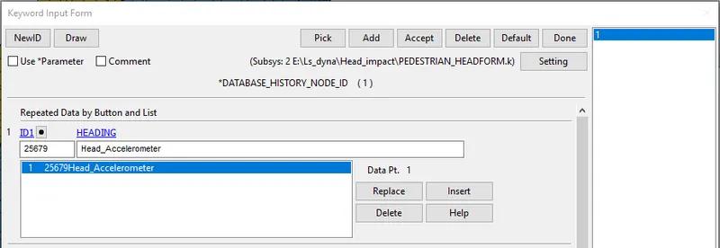
DATABASE_HISTORY_NODE: A set of nodes created Below the Head where It will impact to measure the acceleration And HIC value
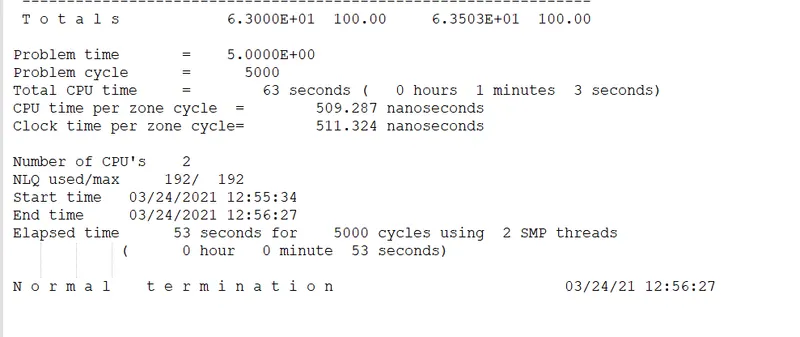
6. Run the simulation
- The keyword is saved in a separate folder and it is opened in Ls-Dyna manager
Results:
Effective stress:
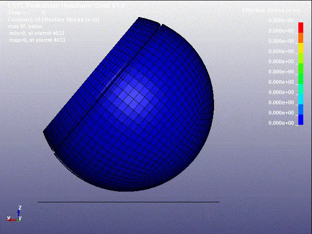
- The Maximum Stress acting On the Head is 0.02456 Gpa at element 15345
- The Minimum Stress acting On the Head is 0.000 at element 4033
Effective strain:
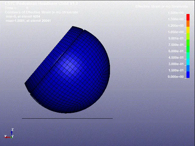
From the simulation it is noted that the maximum strain is 1.50
Graph:
1.Energy graph:
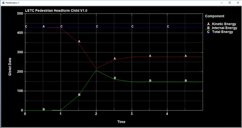
- From The graph, we can see that Total energy Is In a straight line as it satisfies the Law of Conservation of energy, as the Internal Energy produced from the wall is equal to the Kinetic energy of the Head impacting On the wall.
- The Kinetic energy is constant till 1.0 ms And after the impact decreasing Gradually.
2. Acceleration and HIC graph:
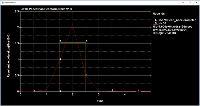
The HIC value recorded in the Accelerometer Is plotted and from the Graph, we can see that the Acceleration is Increased and decreased At 1.70ms As the head Bounces back after rhe Impact.
HIC= 7.604e+04
The HIC average is calculated Between the time interval 1.5 ms to 2.5 ms
Stress vs Strain Graph:
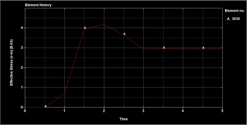
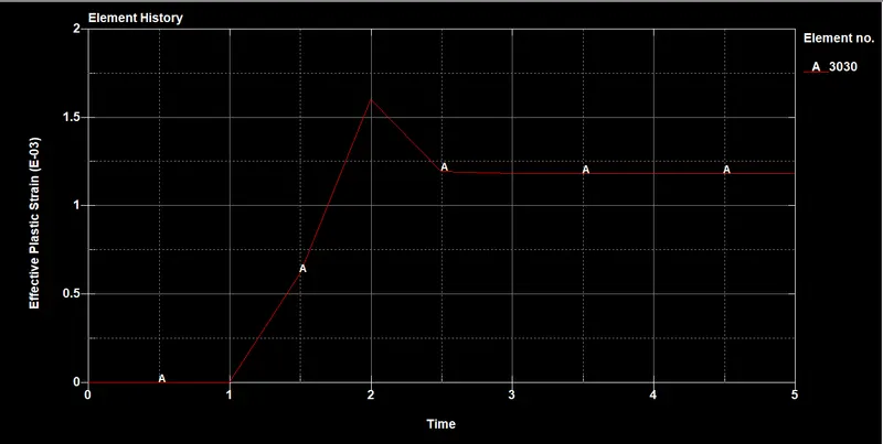
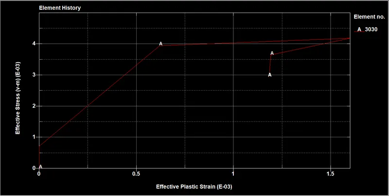
Since the head is rotating during the Impact we can see the rotation in the Axis there
Case 3: Pedestrian head form impact on the hood of a car:
1. Importing the model:
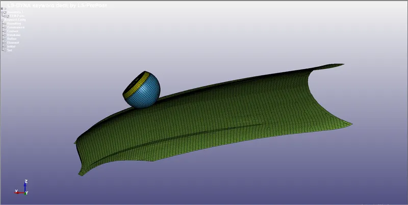
- The Meshed Hood is Imported As per the Automotive Industry standards AIS 100, in a new keyword File.
- The head form is rotated about 45deg release angle using *DEFINE_TRANSFORMATION c
ard similar to previous case - The HeadForm Model is called Using *INCLUDE_TRANSFORM to the Hood Keyword file
- The Keyword is saved in the same Folder With the Hood
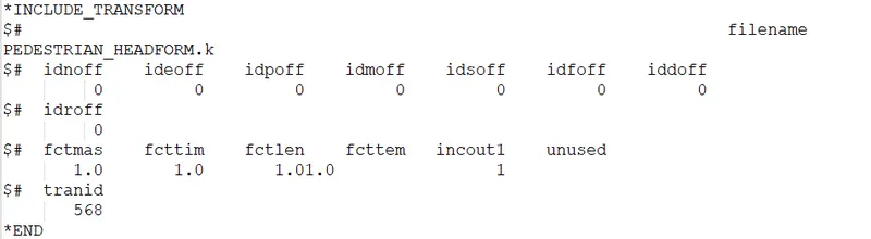
- The Keyword is saved in the same Folder Where the Original Geometry Is Saved.
- Both *INCLUDE_TRANSFORM and *
DEFINE_TRANSFORMATION cards are included with the original geometry - Now the keyword file with *INCLUDE_TRANSFORM and *
DEFINE_TRANSFORMATION is opened in LSPP
2. Assigning the material:
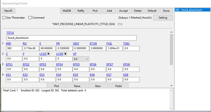
- For assigining the material the following steps are followed Keyword manager `rarr`All `rarr`Mat `rarr` Select the material card, here different material properties like mass density, youngs modulus, poisson's ratio and other recommended values are given
- Mat_24_Piecewise_Linear_Plasticity card with properties of Aluminium assigned.
- Material property of head form is predined.
3.Section creation:
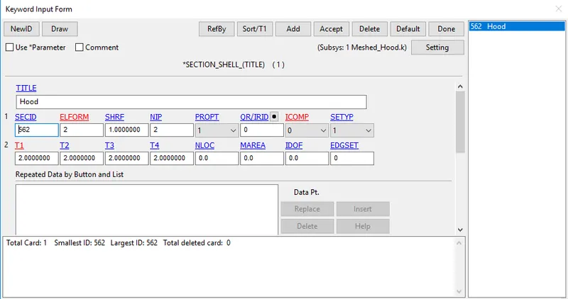
- Shell section is needed to be defined to the hood by selecting Keyword manager `rarr`All `rarr`Section `rarr`Shell
- Here the shell selection with element formulation 2 is defined with the thickness is given as 2mm
- Shell for head form is also predefined here, hence there is no need to create a new section for it.
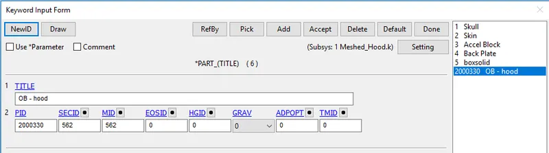
Specifying section and materials to their respective part ID's
- For creating the part Keyword manager `rarr`model `rarr` part is used , then the respective section and material is assigned to it.
4. Boundary Conditions:
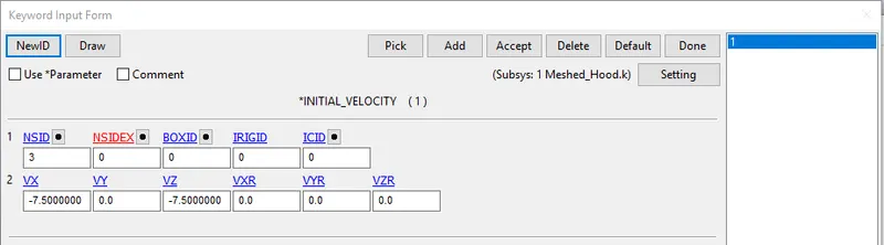
(i) Initial Velocity:
Since the Model is rotated to a certain angle the velocity should be resolved according to the axis
here the angle of rotation is 45 deg,
`implies``V_x`= 11.11 cos 45
`implies``V_z`= 11.11 sin 45
The resolved velocity is 7.5mm/ms since its acting in a negative direction -7.50mm/ms is defined for both `V_x`& `V_z`
(ii) SPC:
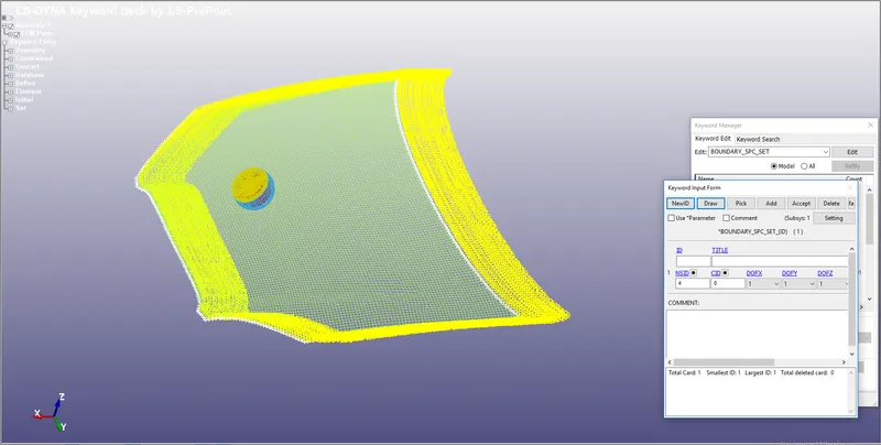
The Corner nodes in the Hood are Constrained in All degrees of Freedom using the Boundary SPC option.
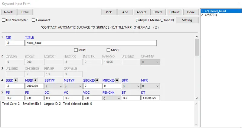
5. CONTACT INTERFACE:
An AUTOMATIC_SURFACE_TO_
6.CONTROL CARDS:
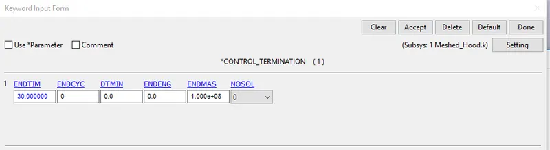
- Control cards such as control energy which is used to specify the control of hourglass energy and control termination which controls the termination of the end time of simulation are specified here
- Keyword manager `rarr`All`rarr` control `rarr` Energy/Termination command is used to define control energy and control termination also there are already predefined cards like Accuracy, Bulk_viscosity, Output and time_step are present.
7.Output Request:
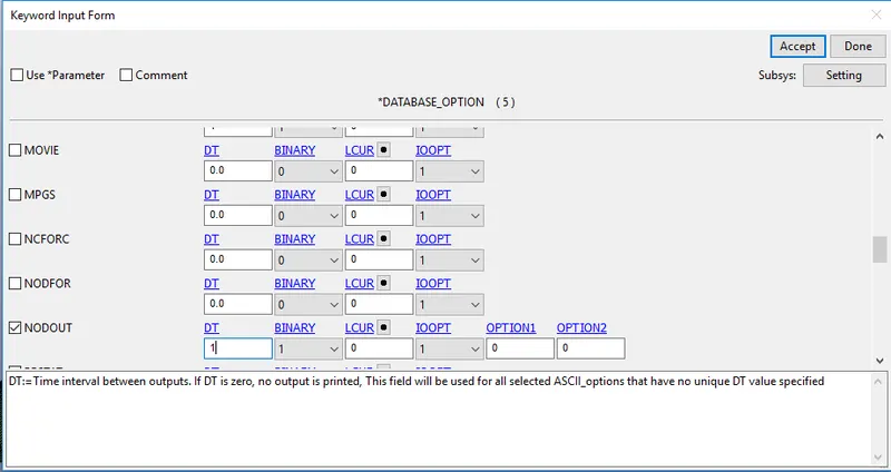
- Generally output resquest are specified to view the results of the simulation which is done by the following commands
- Keyword manager `rarr`All`rarr` Database`rarr` ASCII_option from which GLSTAT,MATSUM,NODOUt option is selected with DT= 1 ms
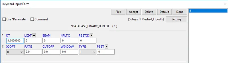
BINARY_D3PLOT: It defines the frequency at which the animation file is to be created and is set to 0.5
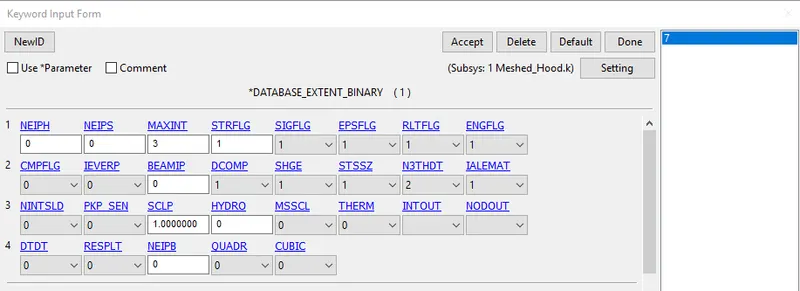
DATABASE_EXTENT_BINARY: This is used to write Strain data to the D3Plot when STRFLG is set to 1
DATABASE_HISTORY_NODE: A set of nodes created Below the Head where It will impact to measure the acceleration And HIC value
8. Run the simulation
- The keyword is saved in a separate folder and it is opened in Ls-Dyna manager
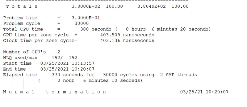
Results:
Effective stress:
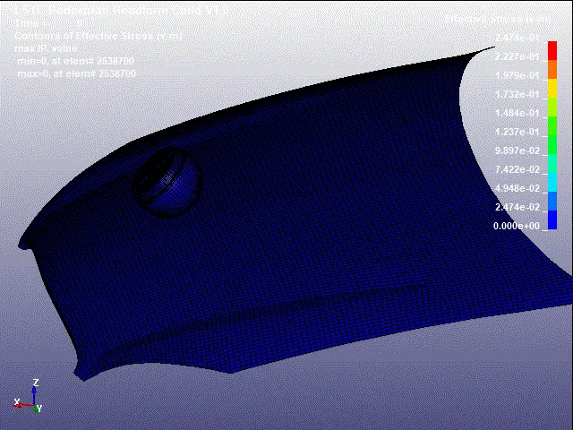
Effective stress is 0.247 Gpa
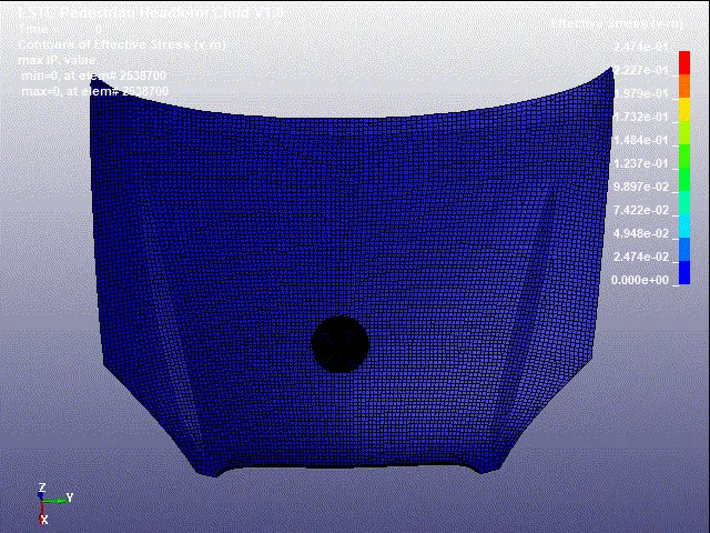
Effective Plastic Strain Values:
Since the Headform is made up of Hyperelastic Material we cant see the stress-strain acting on the head so an element in the Head where it experiences Greater deformation is selected and stress-strain value is Plotted for that
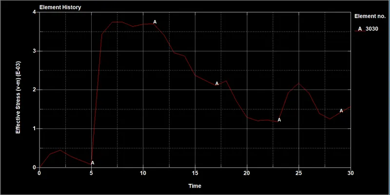
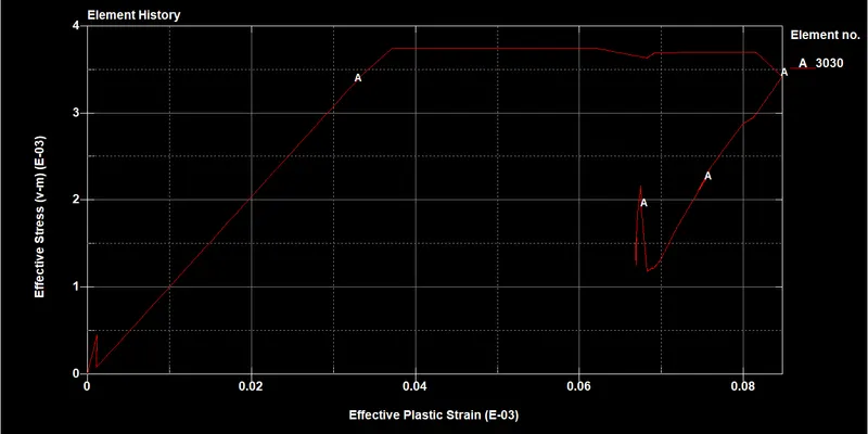
Since the head is rotating during the Impact we can see the rotation in the Axis there
Energy graph:
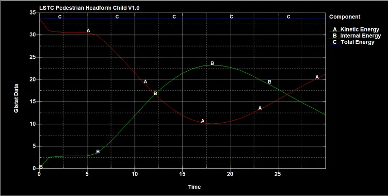
Because of hood deformation, we can see kinetic energy decreases and internal energy increases gradually but in another case because of head foam impacting on the rigid wall there was an abrupt change in energy at impact
2. Acceleration and HIC graph:
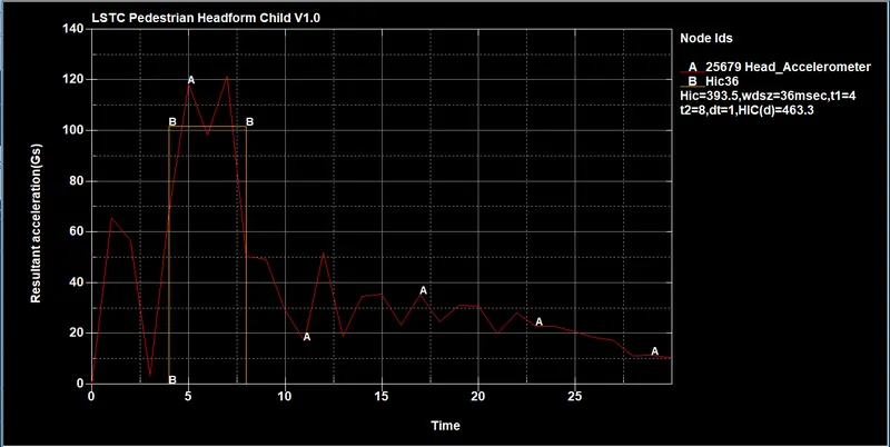
The HIC value recorded in the Accelerometer Is plotted and from the Graph, we can see that the Acceleration is Increased and decreased At 1.70ms As the head Bounces back after rhe Impact.
HIC= 393.5 which is less than HIC Standard protocols HIC value 650
The HIC average is calculated Between the time interval 4 ms to 8 ms
Conclusion:
Thus Head impact analysis on a child pedestrian head using LS PREPOST is performed and the Head Injury Criterion (HIC) for different cases is calculated and the values are plotted.
Link to view files: https://drive.google.com/file/d/1OBDfaXtw7TkN0c6gn1guK5_dZXtgmZAm/view?usp=sharing