Week-7 Head Impact
AIM:-To perform head impact on the automobile hood by using ls_dyna.
Theory:-
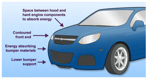
Pedestrian Protection
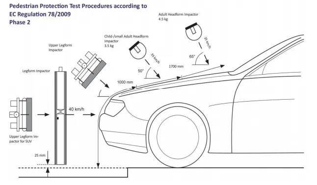
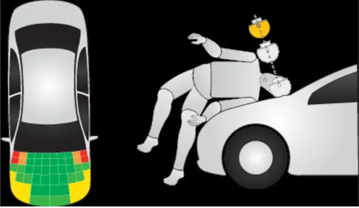
Various tests involving adult and child pedestrian accidents are replicated at 40kmph. Instead of using full-body dummies, specific body parts such as the head and legs are used and they are hit to certain sections of the cars. The deformation on the vehicle body and the dissipation of the energy is checked.
As we are taking full dummies we will be considering the total pedestrian tesh will four tests will be formed which are lower leg test, upper leg test , child head test, adult head test
Lower leg test we will consider a deformable object which is directly impacting the front bumper
upper leg test is the same as roof crash where the plunger will be impacting the edge of the hood
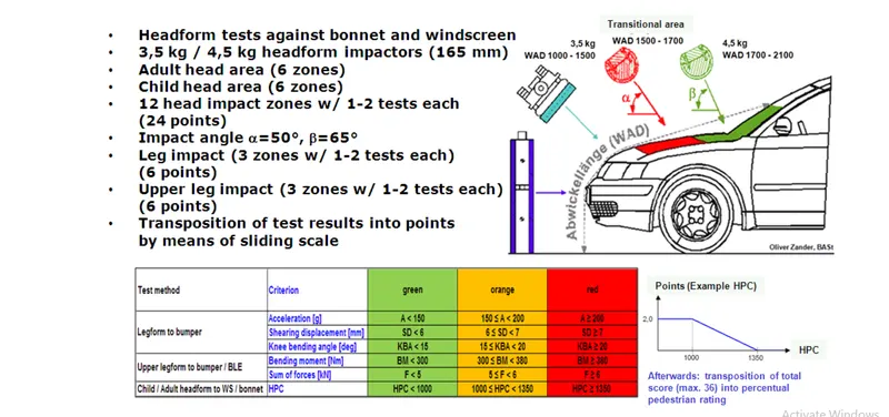
Chid head test where the head will be hitting at 40kmph at 50 degrees and it will hit at the wrap distance of 1500-1700.
Adult head test where the head will be hitting at 35kmph at 50 degrees and it will hit at the wrap distance of 1700-2100.
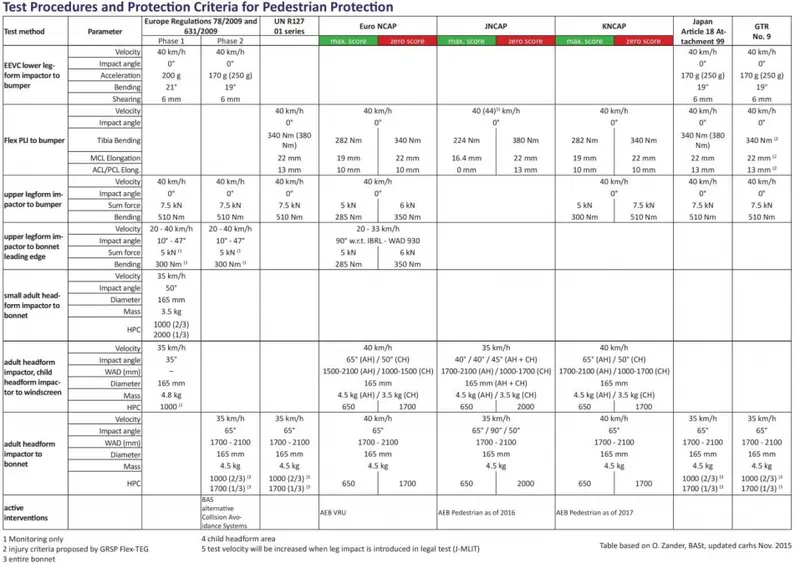
Assessing the impact of the upper leg form to the bumper, the instantaneous sum of the impact forces with respect to time shall not exceed 7.5 kN and the bending moment on the test impactor shall not exceed
510 Nm.
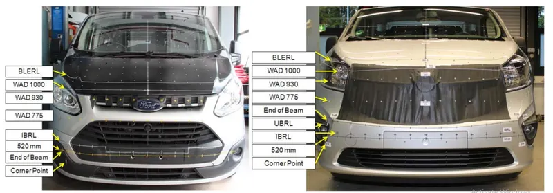
The adult head form test area is an area on the outer surfaces of the front structure. The area is bounded:
(a) In the front, by a wraparound distance (WAD) of 1700 or a line 82.5 mm rearward of the bonnet
leading-edge reference line, whichever is most rearward at a given lateral position;
(b) At the rear, by a WAD 2100 or a line 82.5 mm forward of the bonnet rear reference line, whichever is
most forward at a given lateral position, and
(c) At each side, by a line 82.5 mm inside the side reference line. The distance of 82.5 mm is to be set
with a flexible tape held tautly along the outer surface of the vehicle.
The child headform test area is an area on the outer surfaces of the front structure. The area is bounded:
(a) In the front, by a WAD 1000 or a line 82.5 mm rearward of the bonnet leading edge reference line,
whichever is most rearward at a given lateral position,
(b) At the rear, by a WAD 1700 or a line 82.5 mm forward of the bonnet rear reference line, whichever is
most forward at a given lateral position, and
(c) At each side, by a line 82.5 mm inside the side reference line. The distance of 82.5 mm is to be set
with a flexible tape held tautly along the outer surface of the vehicle.
The head injury criterion (HIC) is used to evaluate the head injury risk. For the tests using the child and adult headform, the HIC recorded shall not exceed 1000 over two-thirds of the bonnet top test area.
The HIC for the remaining areas shall not exceed 1700 for both head forms. In case there is only a child headform test area, the HIC recorded shall not exceed 1000 over two-thirds of the test area.
For the remaining area, the HIC shall not exceed 1700.
https://ecf.com/sites/ecf.com/files/ECF_AGU%20ZURICH%20final%20report%20on%20passive%20safety.pdf
https://www-esv.nhtsa.dot.gov/Proceedings/25/25ESV-000376.pdf
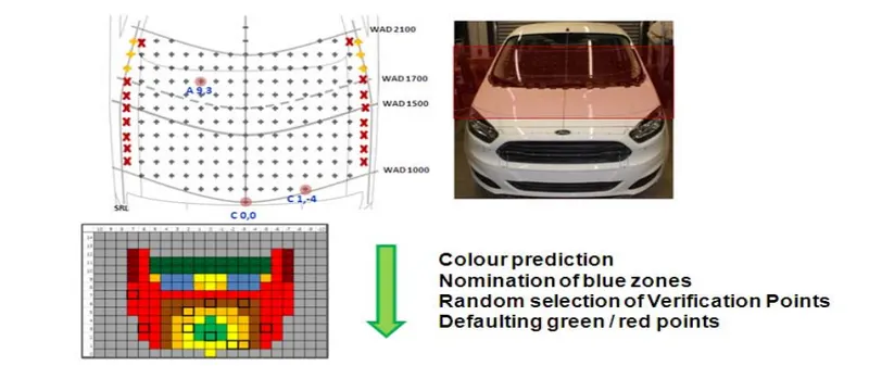
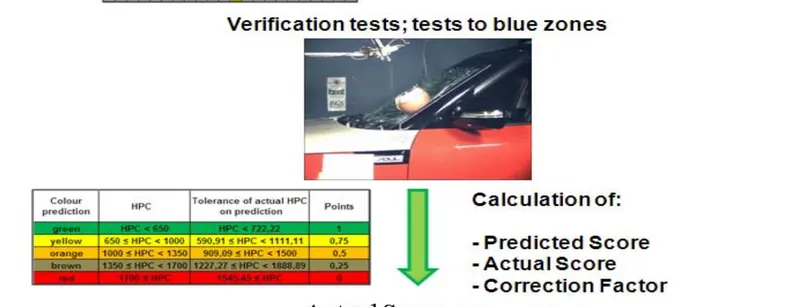
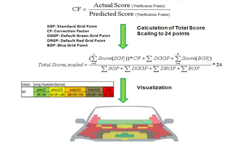
high-performance computing (HPC)
WAD:-wrap around distances (WAD)
PROCEDURE:-
- Import the model to ls pre-post.
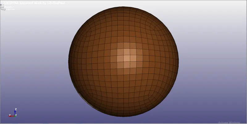
- After importing the model we need to create the rigid wall
- To create the rigid wall we need to go to the model and click on create entities then select the rigid wall and select create.
- Then select the plane and select the node to create the rigidwall.
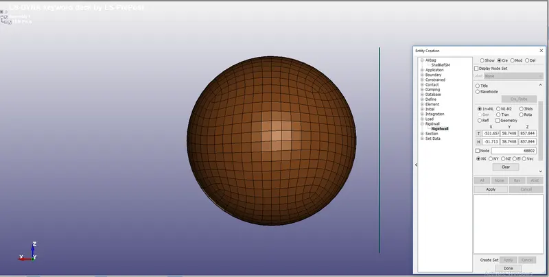
- Create material and sections for the parts.
- The section is considered as a shell with a thickness of 2mm and material as steel.
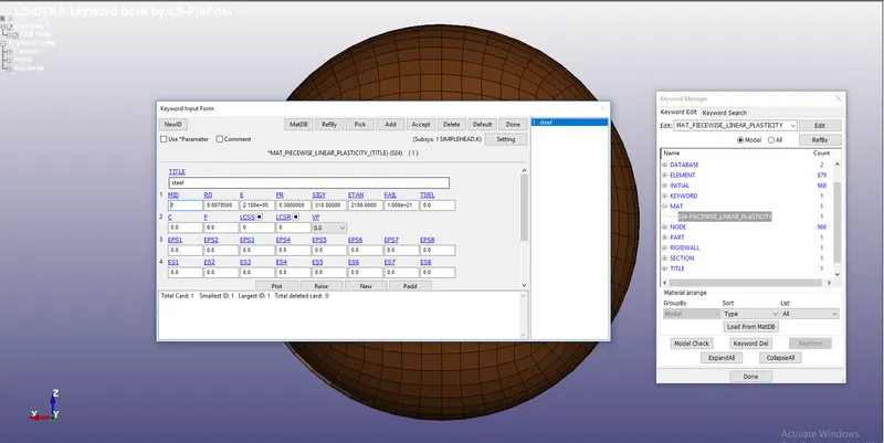
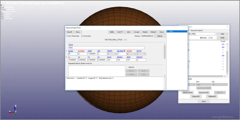
- Then after we need to create the boundary conditions as velocity as 13.86 mm/ms
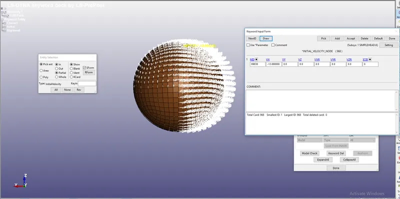
- Then we need to give an output request from database binary and ASCII file.
CASE 2:-
- In this case, they had given a head model.
- By using the command include and include transform keyword we need to rotate the had and we need to run the impact the rigid wall.
- For the first step, we need to open a new ls pre-post file
- Then we need to go to command include and then select the file
- Then we need to define transform and give rotation as 50 degrees and save it with a new keyword file.
- Here A1, A2, A3 are the axis, and the A7 the angle of rotation
- we need to rotate model into 50 degrees in y axis.
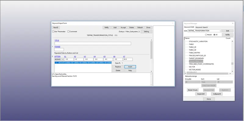
- After we need to include the file that to be transformed and import the TRANID to it.
- We need to save the file with new keyword and select the file only which is to be saved.
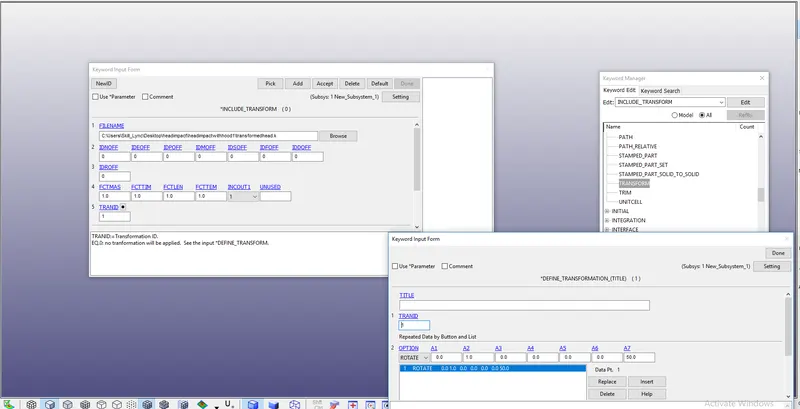
- Then open the transformed head
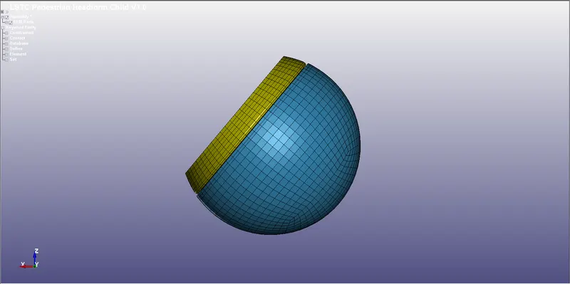
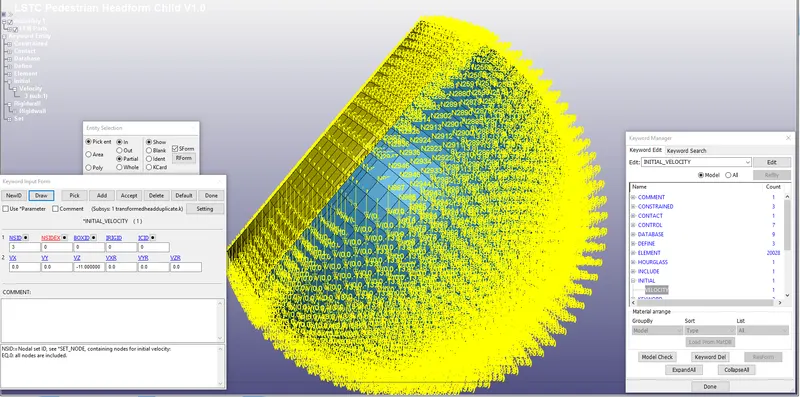
- For this, we need to give velocity and create a rigid wall.
- The same steps are taken as the above case.
CASE 3:-
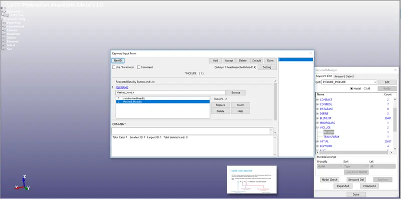
- Take the transformed head file and select include and select the hood and save it with the new filename.
- Then after open that keyword file.
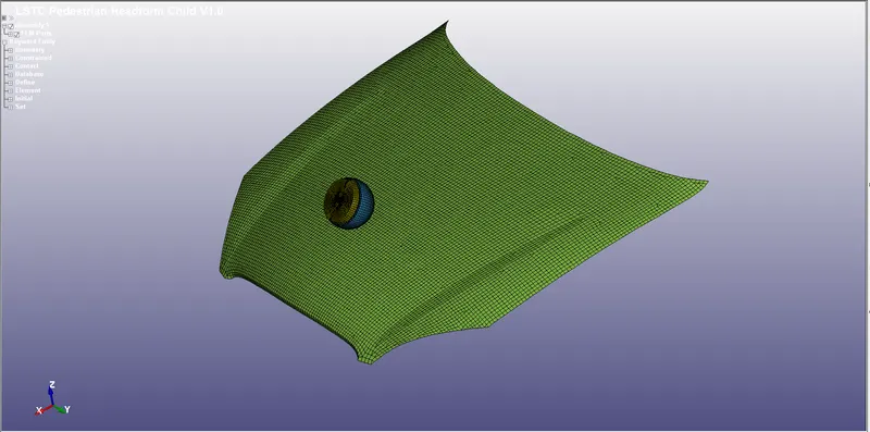
- After getting the file then we need to set material and section properties for the hood.
- Here we are considering the material for the hood is aluminum and thickness is 2mm.
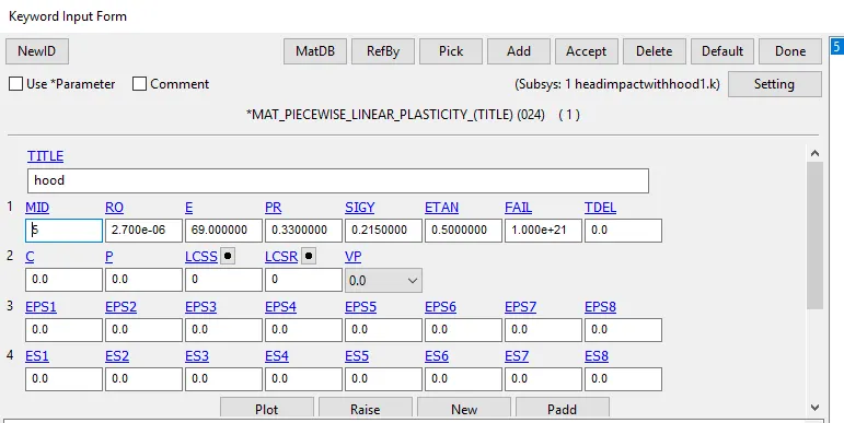
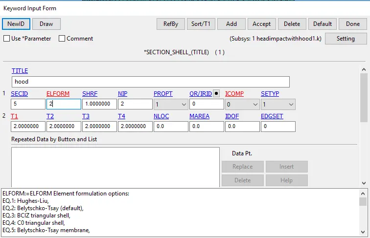
- Then after we need to give boundary conditions and output requests.
- For the head, we need to give the velocity of 11 mm/ms.
- After that, we need to fix the hood by using an SPC lock-in all DOF.
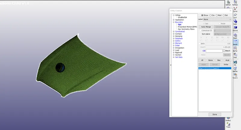
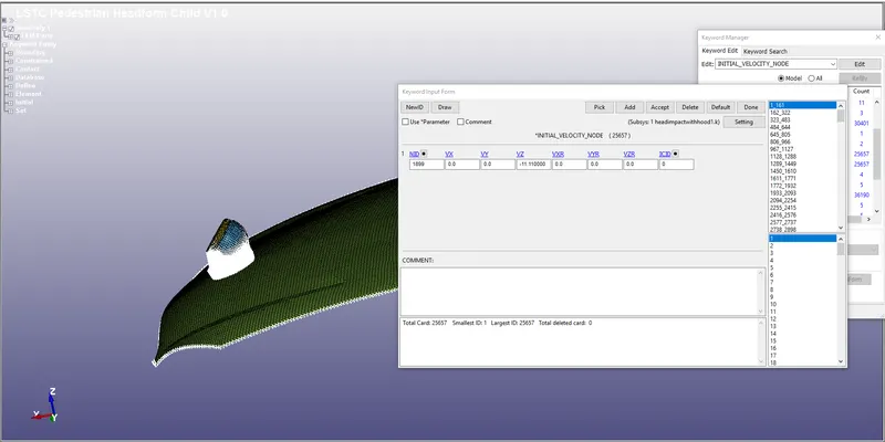
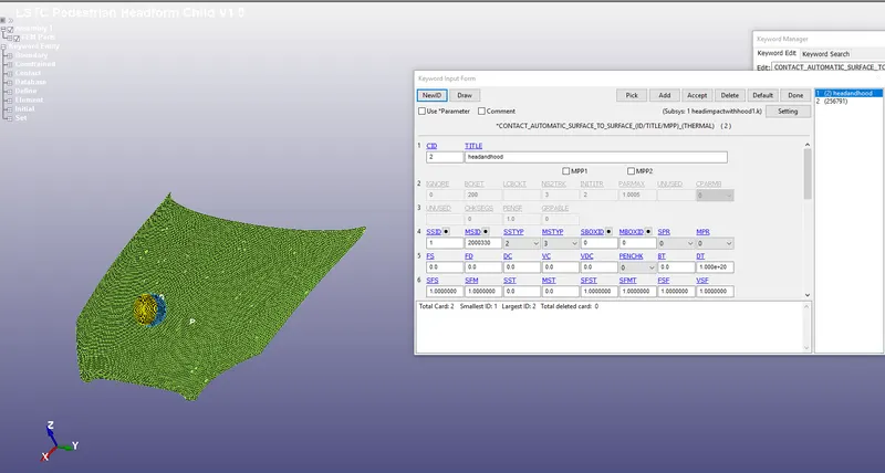
- After this, we need to make a contact between the head and the hood.
- Which will be given as automatic surface_surface contact, where the head is slave and master as a hood.
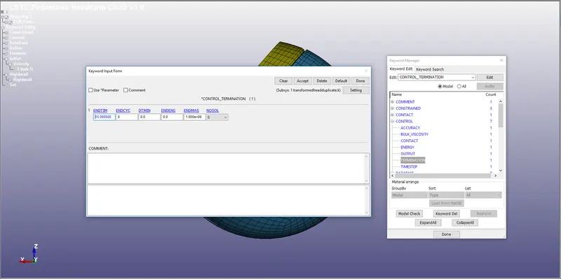
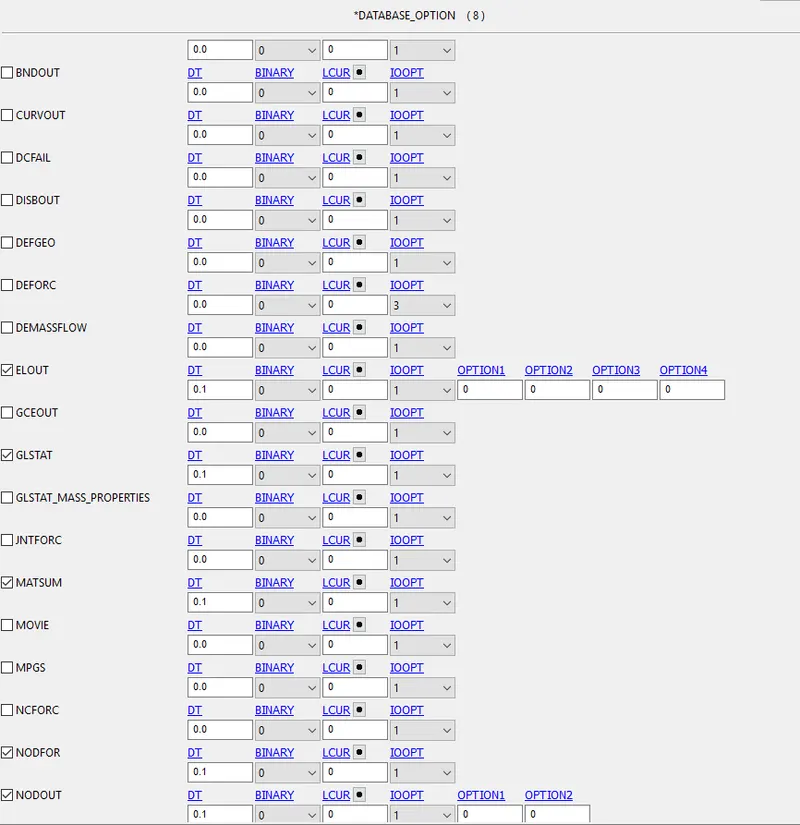
- Then we need to give output requests to check the results like termination time and ASCII, Binary d3plot.
- Where in ASCII we will define the GLSTAT, NDOUT, RWFORC, SPCFORC, ELEOUT, etc...
RESULTS:-
case 1
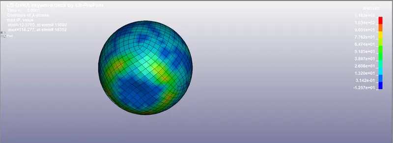
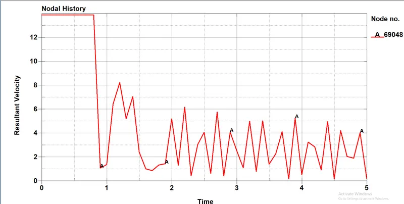
- As we can see that the velocity given is 13.86 mm/ms where the ball is prescribed to have an impact with a rigid wall.
- But from the graph, we can see that the ball was in contact with the rigid wall at 0.85ms.
- At the point of time there huge drop in velocity as it underwent plastic deformation so the velocity is been constantly becoming neutral
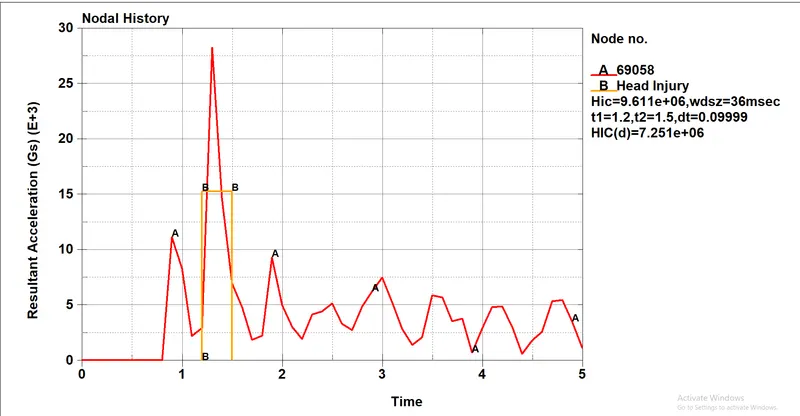
- As we see the peak acceleration is 28e+03mm/ms^2.we can see the Hic value is 9.611e+06 which is more than 1000 which is not recommended.
case 2
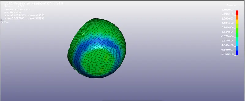
- Here we consider the Odgen material model for impact to a rigid wall, whereas the material is hyper-elastic material.
- The max stress attained by the component is 2.7e-03 N/mm^2
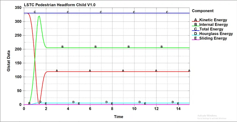
- The energy has been balanced where the maximum energy is attained as 345 gm-mm^2/ms^2
- Where we can see the hourglass is also constant where it was been constrained.
- There was the sudden rise of K.E after the collision due to elastic property which can regain it shape whenever the load is removed.
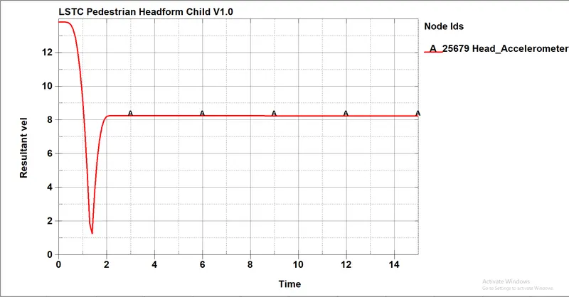
- Here the velocity decreased gradually and then after it attained a velocity
- After a huge drop in velocity but it attained the constant velocity with less span of time.
- The velocity is attained by a head after a crash is 8 mm/ms.
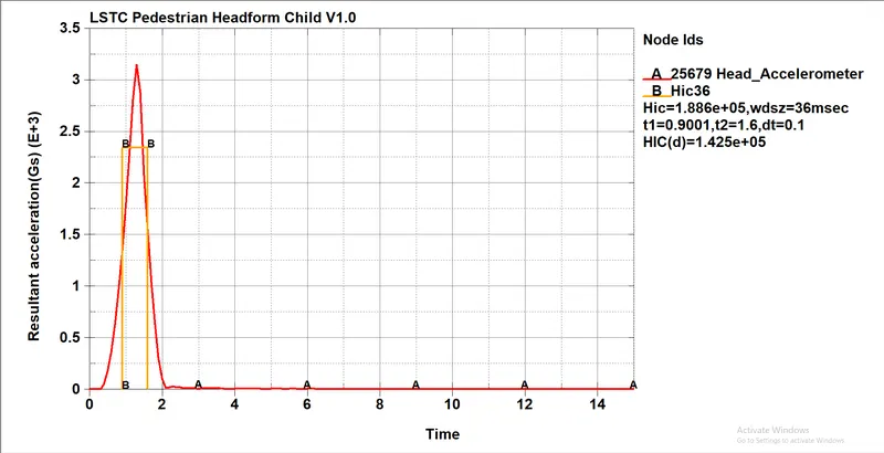
- Here the head going to impact the rigid wall where zero deformation happened to the rigid wall, the force exerted by the wall which will be high.
- Because of that there is deacceleration that happened as same as the head impacted to the wall there is less time difference for the body.
- The HIC value is also high 1.88e+06 which is also not accepted.
CASE 3:-
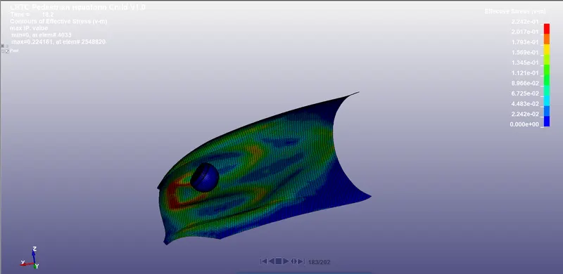
- Here we consider the Odgen material model for impact to a rigid wall, whereas the material is hyper-elastic material.
- The max stress attained by the component is 2.4e-01 N/mm^2
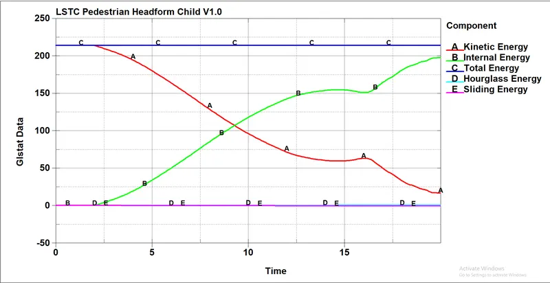
- The energy has been balanced where the maximum energy is attained as 210 gm-mm^2/ms^2
- Where we can see the hourglass is also constant where it was been constrained.
- There was a sudden rise of K.E after the collision due to elastic property which can regain its shape whenever the load is removed.
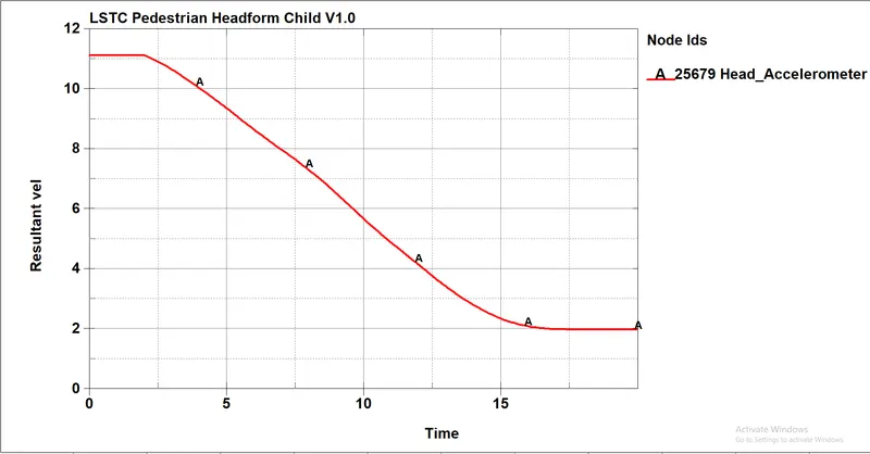
- So we can see that the velocity attained by a head after impact is 2mm/ms a huge drop that can help to reduce the impacted energy.
- As we see that the deceleration time has been an increase so that the risk of the injury is less.
- Where the HIC value of case 3 is 735.8 which can be accepted the injury rate of the head is less compared to all their cases.

HIC(d)=0.75446(Free Motion Headform HIC)+166.4.
- The area under the curve is 78*10^-3 where t1=2.3 and t2=16.6
t2-t1=14.3
By calculating manually
=78^2.5*14.3=768373.79*10^-3
=768.37
HIC(d)=0.75446(Free Motion Headform HIC)+166.4.
=0.75446*768.37+166.4
=746.10
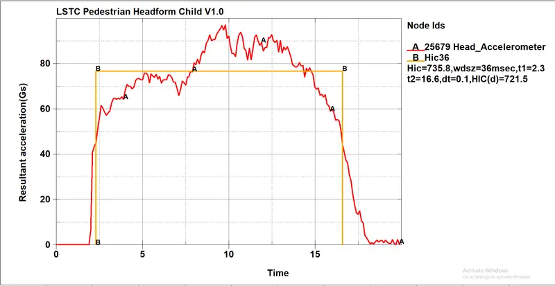
- As we calculated manually the results are equal.
Conclusion:-
- Understood how to perform head impact and how to approach the problem.
- Understood criteria of head impact analysis
- Understood and performed manual calculation for HIC value.