Week-7 Head Impact
AIM:
To perform the impact simulation of a child's head hitting bonnet of a car. This simulation is done in three different case.
Case 1:
A simple head model creating impact with rigid wall
Case 2:
A pedestrian head model creating impact with rigid wall.
Case 3:
A pedestrian head model creating impact with the bonnet of a car.
INTRODUCTION:
Pedesterian death occurs in large part of vehicle-pedesterian accidents. Bonnet is one of the important part which might cause risk of injury in vehicle-pedesterian accidents. Head impact is analyzed by throwing head model onto hood with 50 degree with horizontal axis and HIC (Head Injury Criteria) is calculated. HIC value is also used to evaluate the severity of the injury. HIC value is calculated using the below formula.
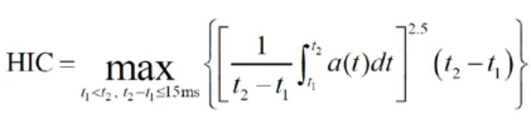
An HIC score of 1000 represents the “safe” limit of human tolerance, above which the risk of a severe head injury is nonzero.
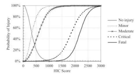
An HIC score correlates to a probability for a level of injury. The minor head injury is a skull trauma without loss of consciousness; fracture of nose or teeth; superficial face injuries. The moderate head injury is skull trauma with or without dislocated skull fracture and brief loss of consciousness. The critical head injury (cerebral contusion) is a loss of consciousness for more than 12 h with intracranial hemorrhaging and other neurological signs. Critics argue that rotational acceleration influences head injury as well. Also, the HIC does not distinguish between specific mechanisms of injury in the head. Despite the limitations of the HIC, it is the most validated HIC to date.
CASE 1:
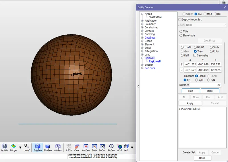
Step 1: Import the given simple head model. It consist of head modelled with shell elements. Then Create a rigid wall in perpendicular to x_y plane. For that go to Model>create Entity>Rigid wall>Create>planar>1n+NL>pick a node>transform>pick a node>give 20mm transform in z direction>click apply.
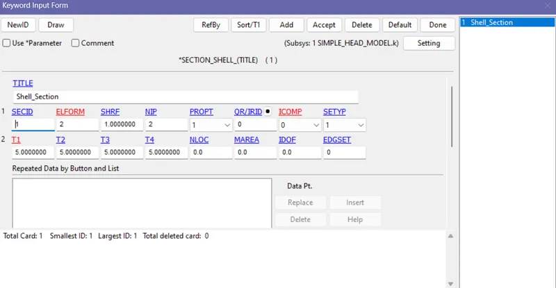
Step 2: Define a section for the simple head model. It is modelled with shell elements so Keyward>section>shell>Enter thickness> accept>done.
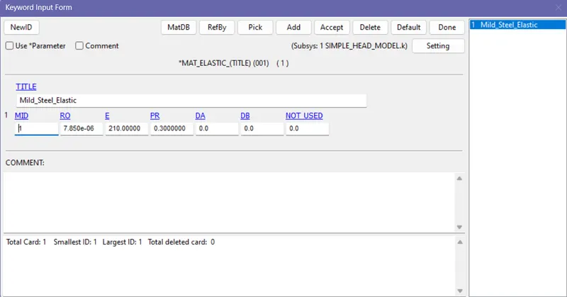
Step 3: Define a material. Steel property is used. The unit system used is kg/mm/ms. So after converting all the properties to the desired unit system go to mat> 001_Elastic card is used> enter the Density as 7.85e-06>enter Youngs modulus as 210>enter poisson's ratio as 0.3> ok.
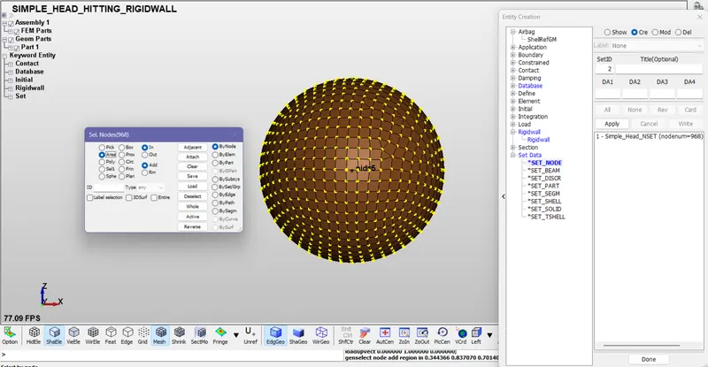
STEP 4: Creating node set to apply initial velocity. Go to model>create entity> Set data> set_node> select all the nodes>apply.
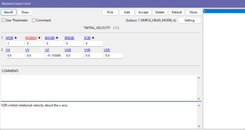
STEP 5: For defining velocity go to keyward>initial>velocity>select the node set id> give the velocity in z direction as -11.11mm/ms(40kmph).
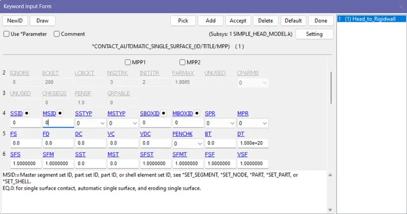
STEP 6: CONTACT: Since there is one shell head model which create impact with rigid wall. So Automatic single surface contact is used. Give master set id and slave set id as zero to represent it as single surface contact.
STEP 7: Database: Define a history node to get data for NODOUT. Then select D3Plot, in ascii output select GLstat, matsum, nodout, Rwforc. Enter step size as 0.1.
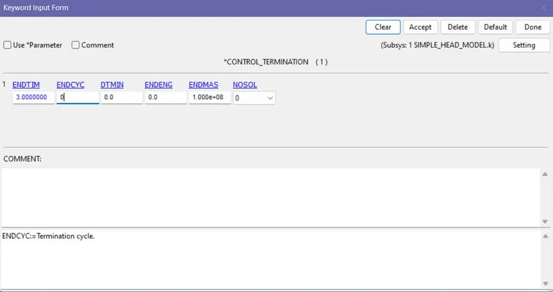
STEP 8: Control>Termination to define the end time of the simulation(3ms). The velocity of the head is -11.11mm/ms. Distance between the head and rigid wall is 20mm. It takes 1.8ms to hit the wall. So the termination time should be greater than 1.8ms.
STEP 9: POST PROCESSING:
EFFECTIVE STRESS:
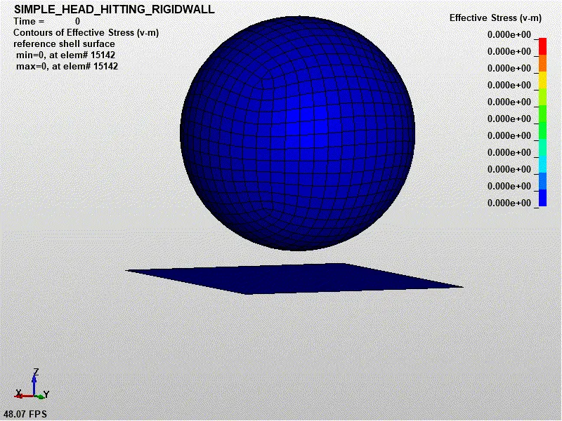
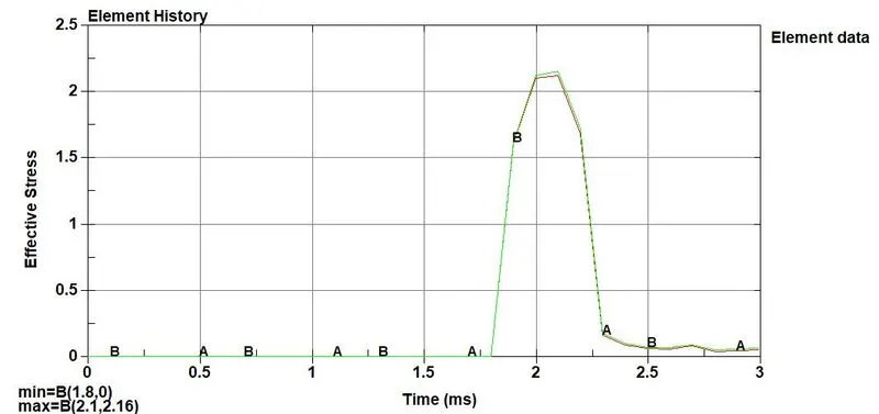
The Effective stress obtained is 2.157GPa
EFFECTIVE STRAIN:
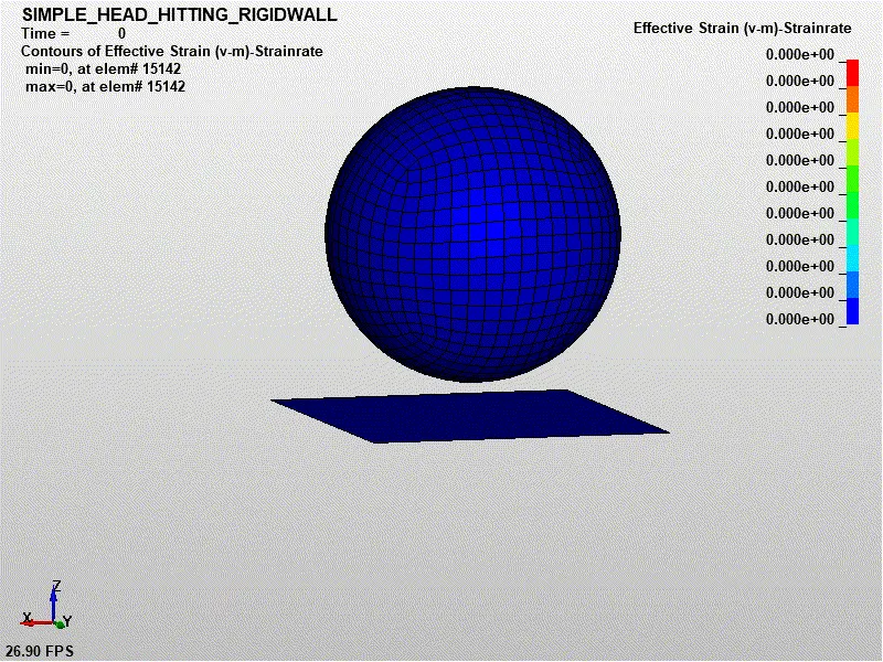
The effective strain obtained is 0.0449mm
HEAD IMPACT CRITERIA(HIC):
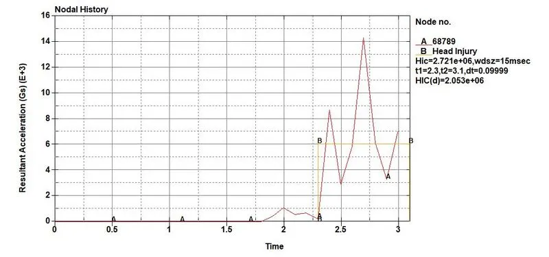
The model simulates with head accleration pulse not longer than 22.4 ms which means HIC 15 gives desired results. So no need to calculate HIC_36. If the model has the head accleration pulse longer than 22.4ms HIC 15 will not give conservative results hence HIC_36 is used.
HIC_15 value is obtained as 2.721e+06 which is very high severe injury. Since the head model creates an impact with rigid wall. Rigid wall is not a deformable object. So equal and opposite amount of force is given back by the rigid wall to the head model. So the stress induced is higher hence results is high HIC value.
CASE 2: Pedesterian head model creates impact with rigid wall with angle of incident 50 degree with horizontal axis.
STEP 1: Importing cad model using transform card.
- Now save this file as main.dyn
- This file is considered as main file which means all the changes that we made will be stored in this main file and the included file remains the same.
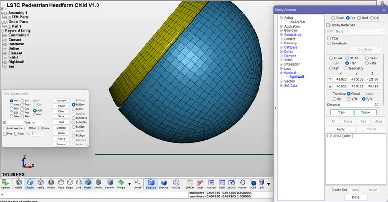
STEP 2: Create a rigid wall with respect to xaxis using create entities>rigidwall>create>pick a node> planar>1n-N1> Transform>z axis>20mm>apply.
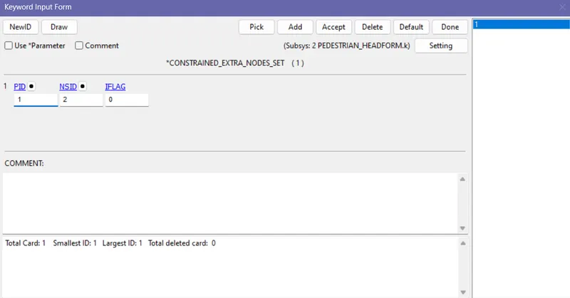
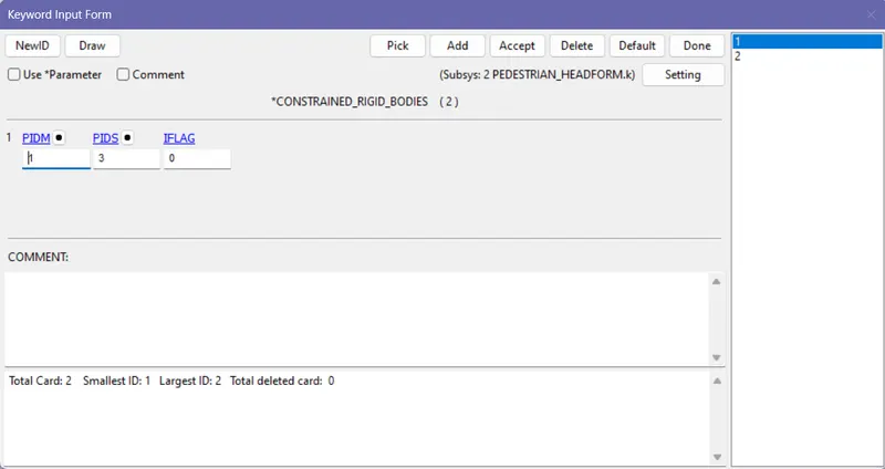
STEP 3: The material for this pedestrian model is already created and defined. This pedestrian model consist of Skin, Skull, Back_plate, Accelerometer. Skin and skull are connected with Constrained extra_nodal rigid body. the skull and Back_plate are connected using constrained rigid body. The Back plate and accelerometer are connected using constrained rigid body. To connect rigid and deformable body constrained extra_nodes are used. To connect two rigid body mspair or constrained rigid body is used.
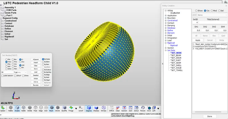
STEP 4: A local coordinate card is created to define the initial velocity at 310 degree. Now create a node set using create entity>set data>set node> select all the parts>apply.
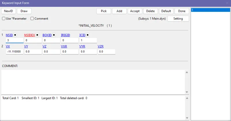
Now go to keyword>initial>velocity>select the node set id>select the local coordinate system id> enter velocity value as 11.11mm/ms(40kmph) along x direction.
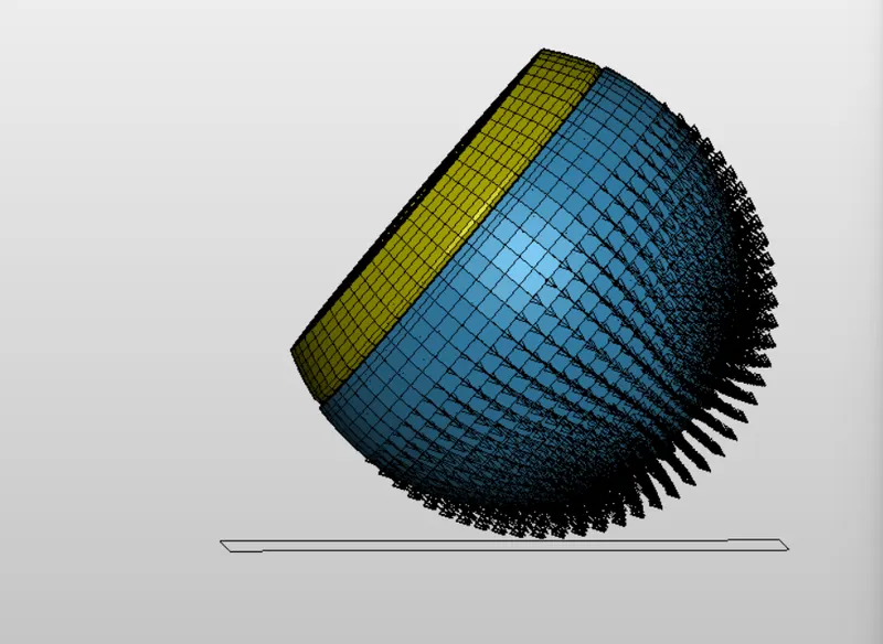
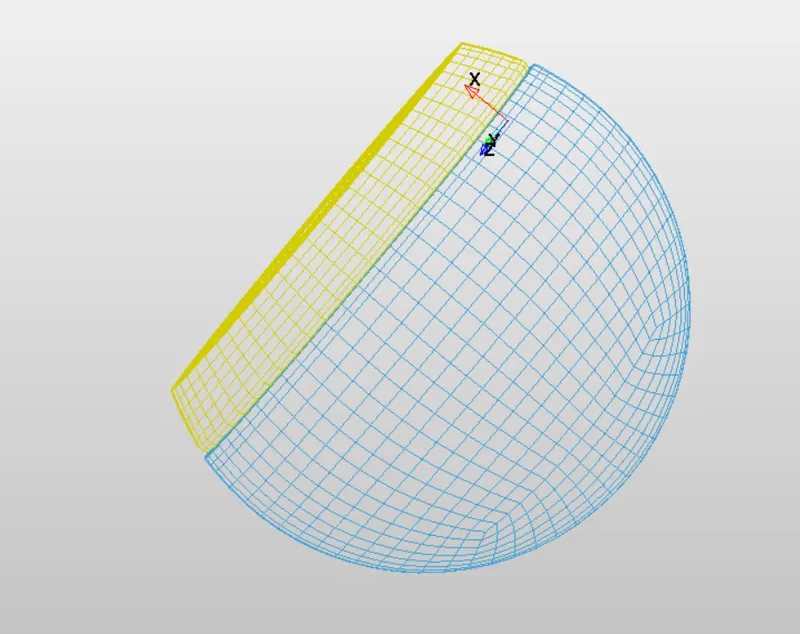
The above image shows the defined local coordinate.
STEP 5: CONTACT:
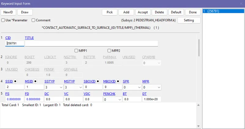
Automatic surface to surface contact is defined between the Skin and Skull to avoid penetration and deformation.
STEP 6: DATABASE:
- Binary D3_Plot with time step of 0.1ms
- Ascii output - Nodout, glstat, Rwforc, Matsum
- Database history node.
STEP 7: CONTROL:
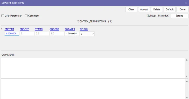
- Termination - The termination time is given as 4ms.
STEP 8: POST PROCESSING:
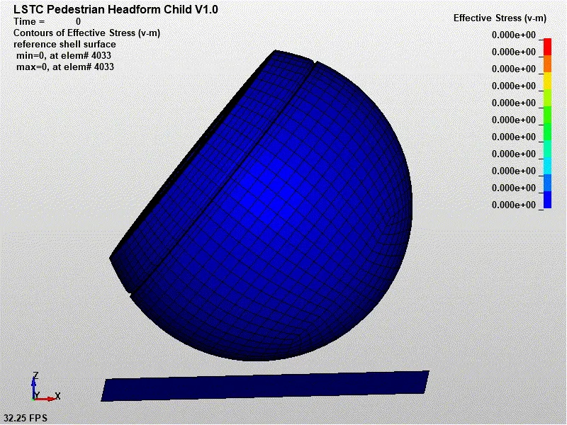
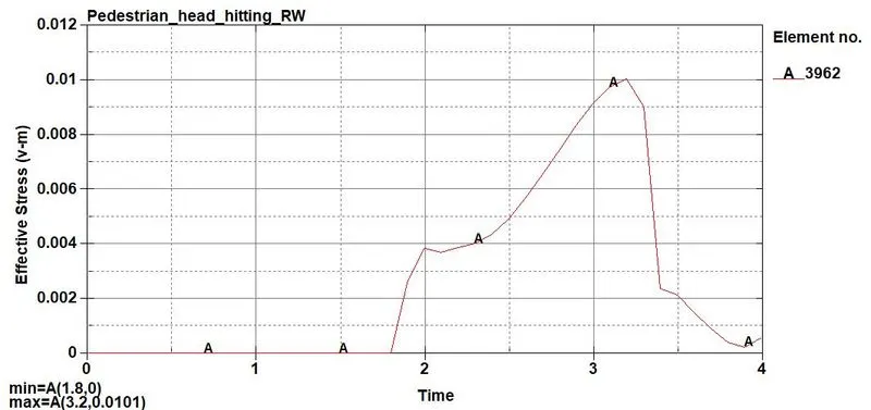
EFFECTIVE STRESS:
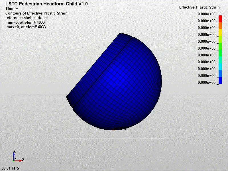
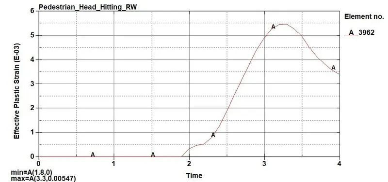
EFFECTIVE STRAIN:
Head Impact Criteria(HIC):
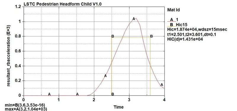
The HIC_15 value obtained as 1.874e+04. Since the head foam is ogden material which is hyper elastic, deforms more. Thus the stress induced is smaller. But the pedestrian head model is hitting the rigid wall which has zero deformation. So the HIC value is comparatively higher. From the resultant accleration graph it is observed that initially the body moves with constant velocity of -11.11mm/ms so no changes in accleration. At time 1.8 ms the impact between pedestrian head and rigid wall occurs. The skin which is hyper elastic deforms rapidly results in increase in accleration. After the impact at time 3.2ms, it bounce back and starts displacing opposite to the rigid wall. This tends to decrease in accleration.
CASE 3: PEDESTRIAN HEAD MODEL HITTING A BONNET OF A CAR AT AN ANGLE 50 WITH HORIZONTAL AXIS.
STEP 1: Include Pedestrian head model and the meshed hood model.
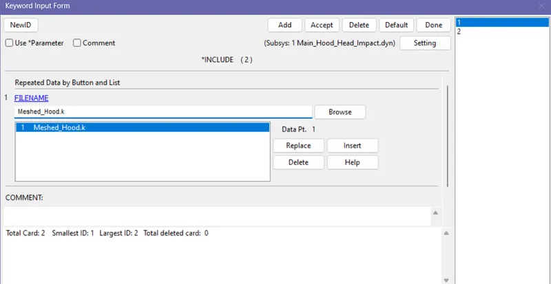
Go to keyword>include>Browse and select the file>insert>done.
For importing and positioning the head model use include>transform>select the head model>enter trans_id>done.
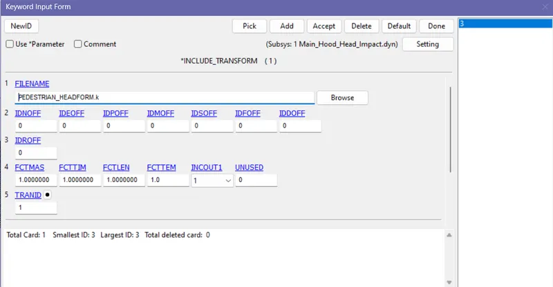
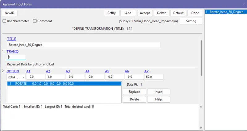
Now go to define>transformation>enter a1=0, a2=1, a3=0, a4=0, a5=0, a6=0, angle=50.
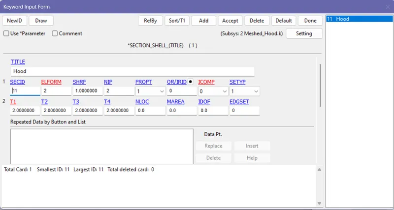
STEP 2: For the meshed hood model, shell section need to be defined. Go to keyword>section>shell>given thickness values>accept.
Step 3: For hood model, mat elastic material card is used and the properties are drescribed according to kg/mm/ms unit system.
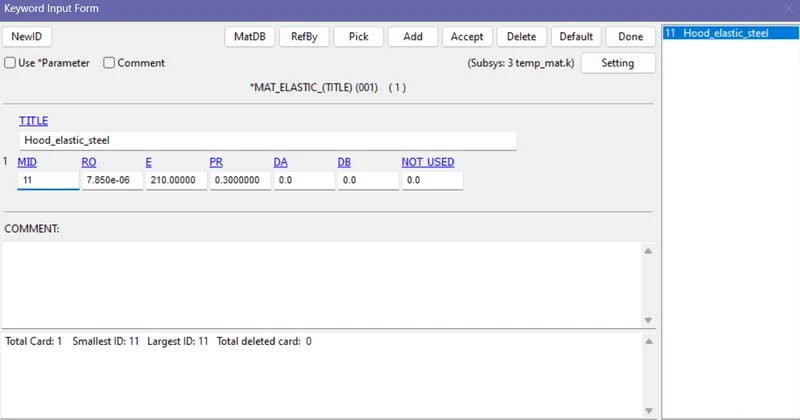
Now go to part id and assign the corresponding material and section.
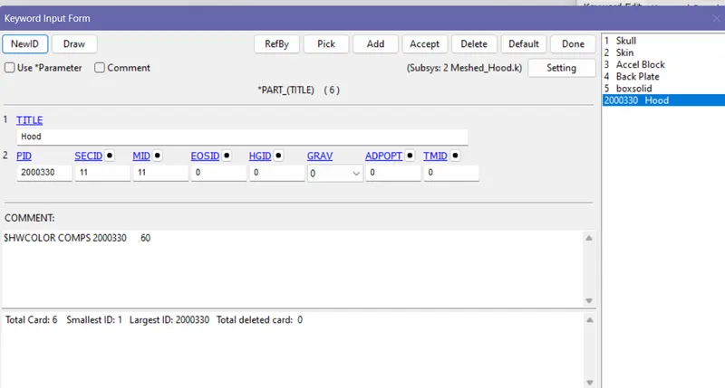
STEP 4: Boundary conditions:
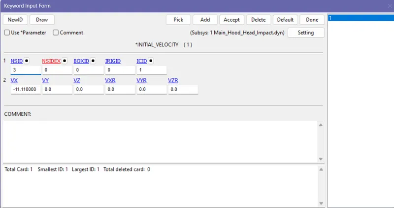
The simulation setup is that the hood is constrained at the edges and the head model hits the hood at the velocity 11.11mm/ms at an angle 50 degree to the horizontal axis(global coordinate axis).
Now for constraining the hood go to model>create_entities>set data>set node>by path>select the edge of the hood>done.
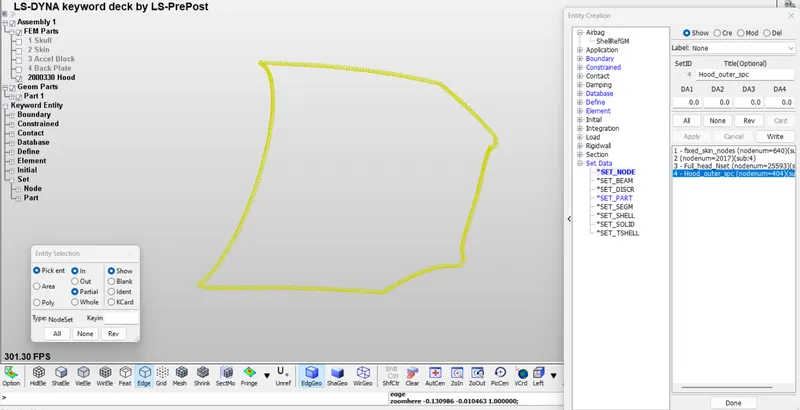
Now go to Boundary>spc_set>select the node set>constrain all the degrees of freedom>done.

Now create the node_set for the pedestrian head model and go to initial>velocity>Select the node set>select the local coordinate id> enter the velocity>done.
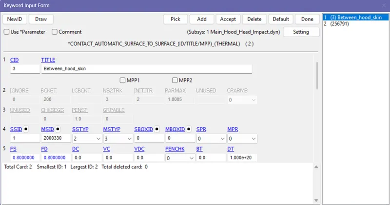
STEP 5: CONTACT:
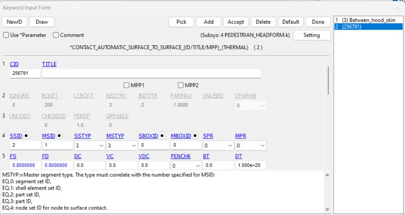
Automatic surface to surface contact is defined between hood and the skin. Master_set_id is the hood and the slave set is the skin of the head model.
Automatic surface to surface contact is given between the skin and the skull(inner sphere). Master set is the skull and the slave set is the skin.
STEP 6: CONTROL :
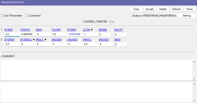
CONTROL_TIME_STEP: This control card is used to control the time step size.
DTINIT - Initial time step size given as zero (LS DYNA will determine the INITIAL TIME STEP itself)
TSSFAC - Time Step Scale Factor given as 0.9(default)
The new time step is determined by mulitplying TSSFAC with min (time step of all elements) as shown below.
 Where N represents no of elements.
DT2MS - Time step size for mass scaling. - Since our problem is not quasi static type or time history analysis negative values are used. Mass scaling refers to non physical mass added to a structure in order to achieve a larger explicit time step.
LCTIM - Load curve id to define the maximum time step size.
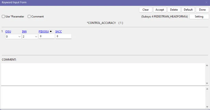
CONTROL ACCURACY:
INVARIANT NODE NUMBERING: If the element numbering is permuted, the results will change in irregularly shaped elements Which tends to improve the accuracy of the solution.
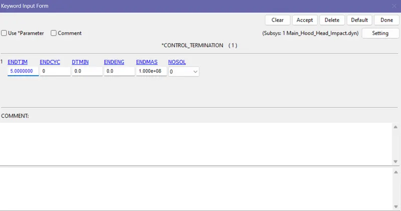
CONTROL TERMINATION:
Defines the end time of the termination given as 5ms.
DATABASE:
ASCII OPTION: GLSTAT, NODOUT and MATSUM.
BINARY_D3_PLOT: Records animation.
HISTORY_NODE: Records data for Nodout.
STEP 7: POST PROCESSING:
EFFETIVE STRESS:
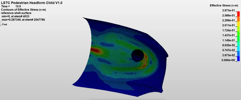
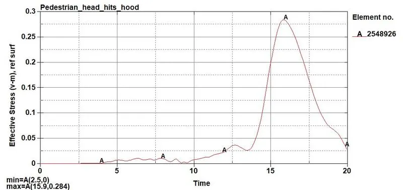
Maximum stress obtained is 0.284 GPa
EFFECTIVE STRAIN:
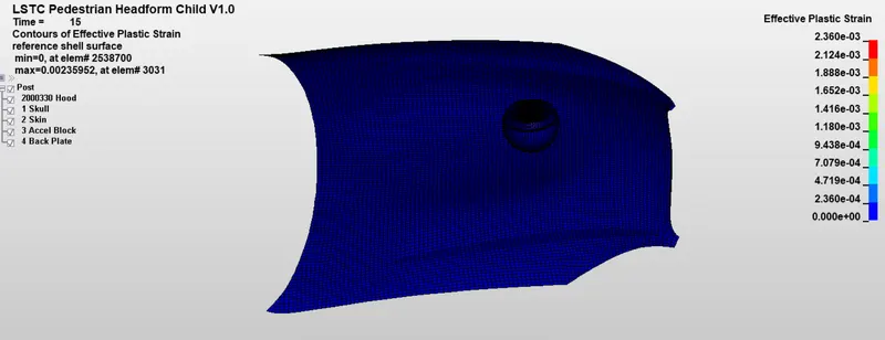
Maximum strain obtained is 0.00236mm.
Kinetic energy vs internal energy vs total energy:
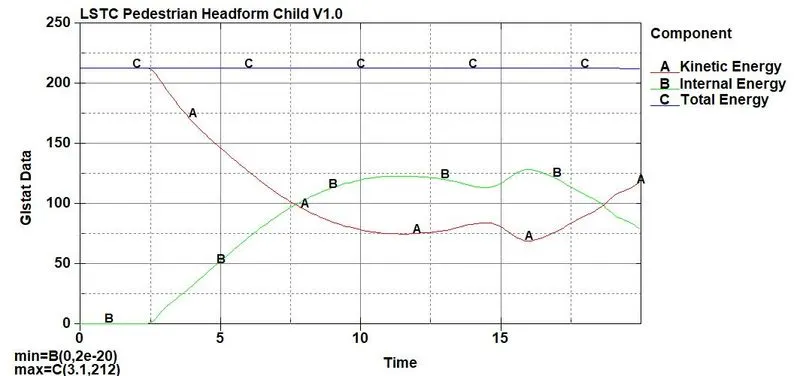
At 2.5ms the Pedestrian head creates and impact with the hood. From 2.5ms the kinetic energy continuously decreasing and it is stores as internal energy. Thus internal energy tends to increase correspondingly. After some time (18.5ms) the head bounce back thus the internal energy is converted into kinetic energy.
HEAD IMPACT CRITERIA (HIC):
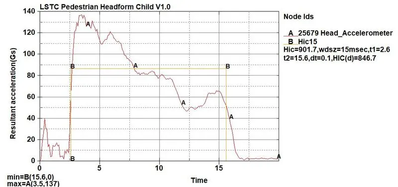
From HIC_15 criteria hic value is obtained as 901.7 and it is achieved because compared to previous case, the hood is not rigid wall so the hood tends to deform so that the stress induced on the pedestrian head reduces hence reduce the probability of high head injury.
CONCLUSION:
In case 1 the simple head model is hitting the rigid wall and HIC value is very much higher because the head model is elastic material and the rigid wall is not an deformable object. In case 2 the pedestrian head model is used which is again hitting the rigid walll and the HIC value is comparatively lower because the pedestrian head model has outer sphere(skin) as ogen material which is hyper elastic so it deforms more. In case 3 the pedestrian head model hits the hood of a car in this case both the objects are deformable bodies hence results in greater strain and the stress induced is reduced hence an ideal HIC value is achieved.